
✦ 3D Modeling Software
During Week 2, we explored Computer-Aided Design (CAD) by testing different tools for 2D and 3D modeling. For 3D design, I used OnShape and Shapr3D to develop key components of my final project, including the device base for housing electronics and the outer shell for the lighting system.
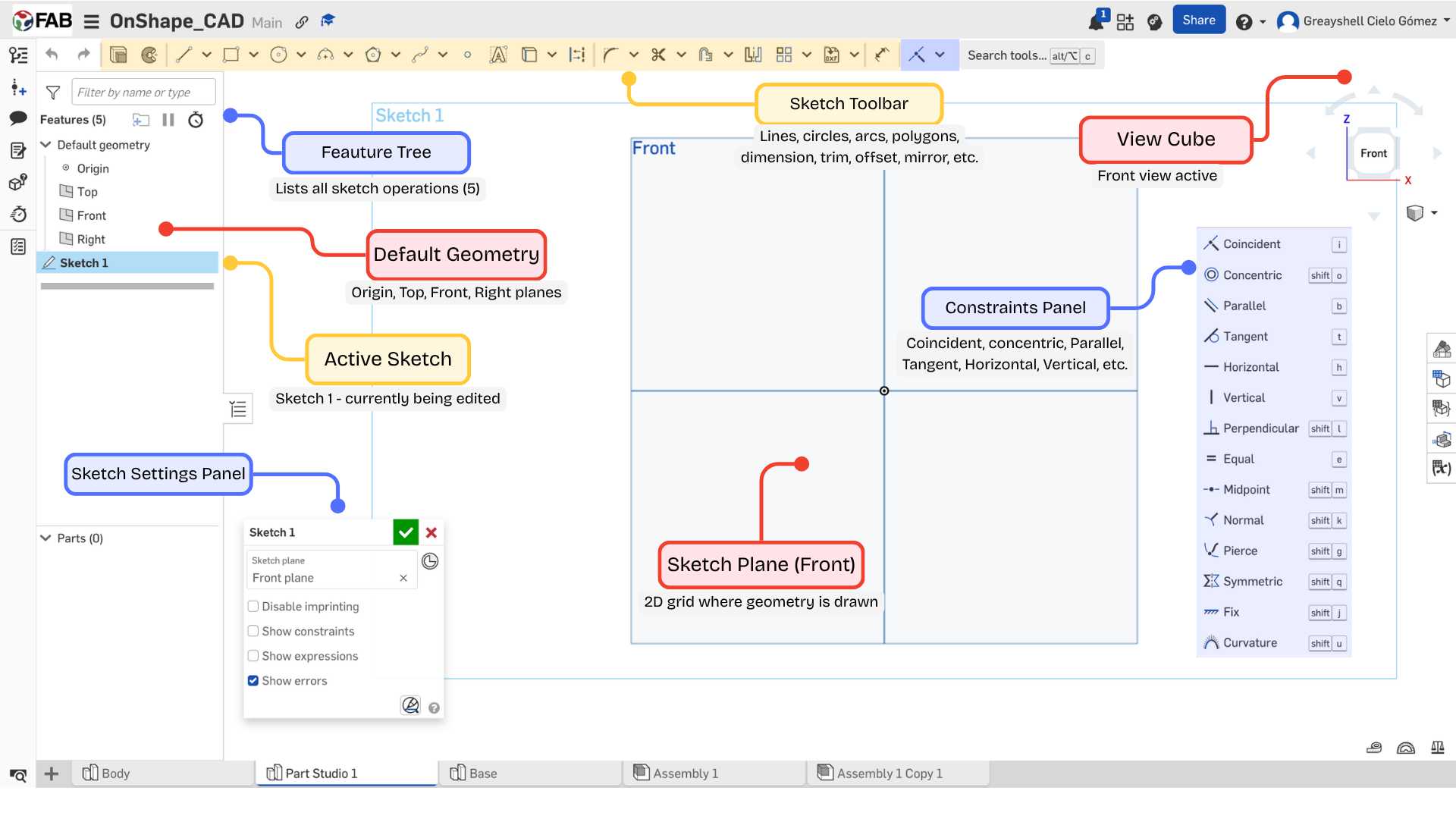
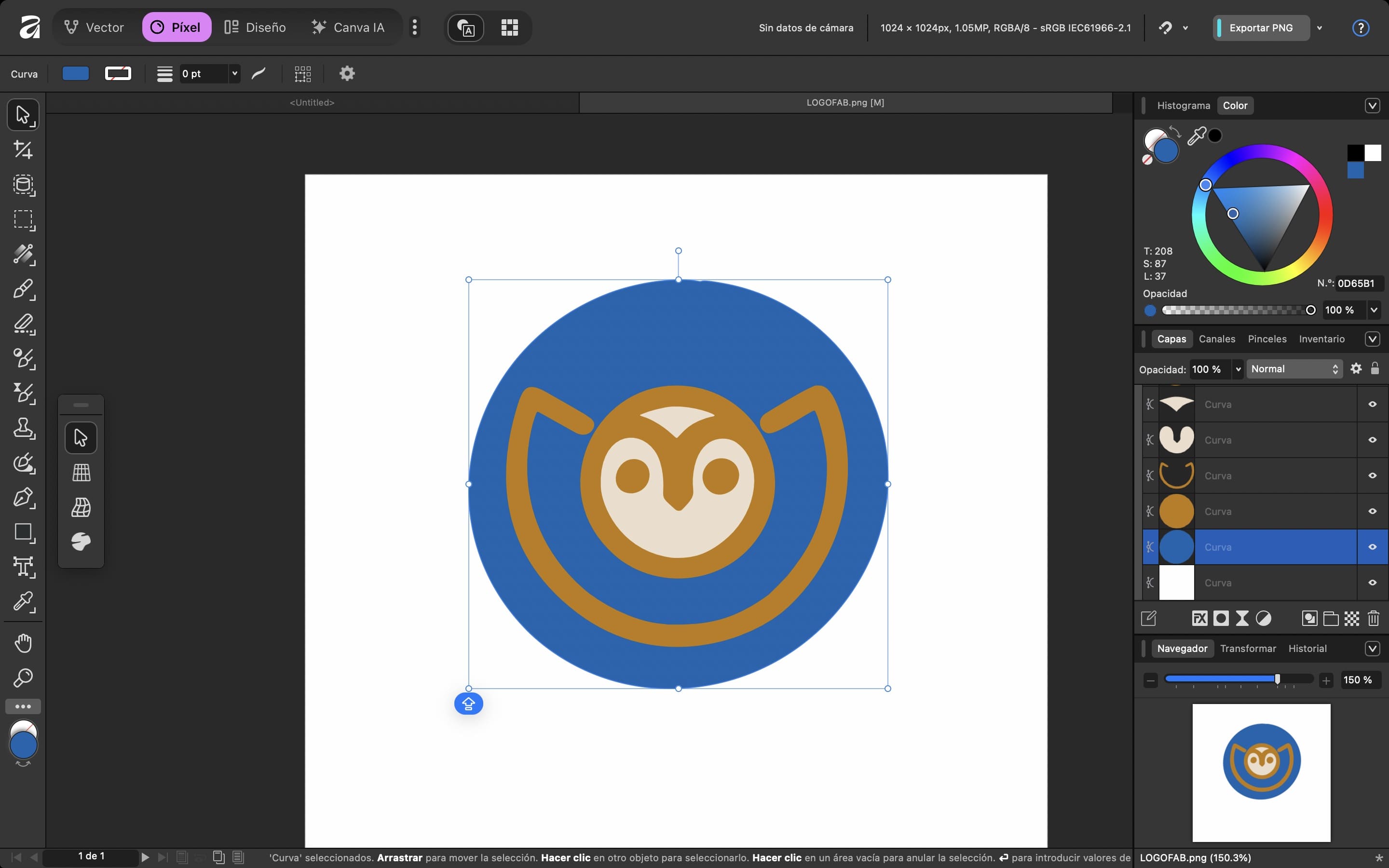
Onshape is a cloud-based 3D design (CAD) and product data management (PDM) platform. Its main functions include creating three-dimensional parts, assemblies, and technical drawings. It is a practical and intuitive program that allows multiple users to collaborate on the same design in real-time, and also maintains a detailed history of every change made.
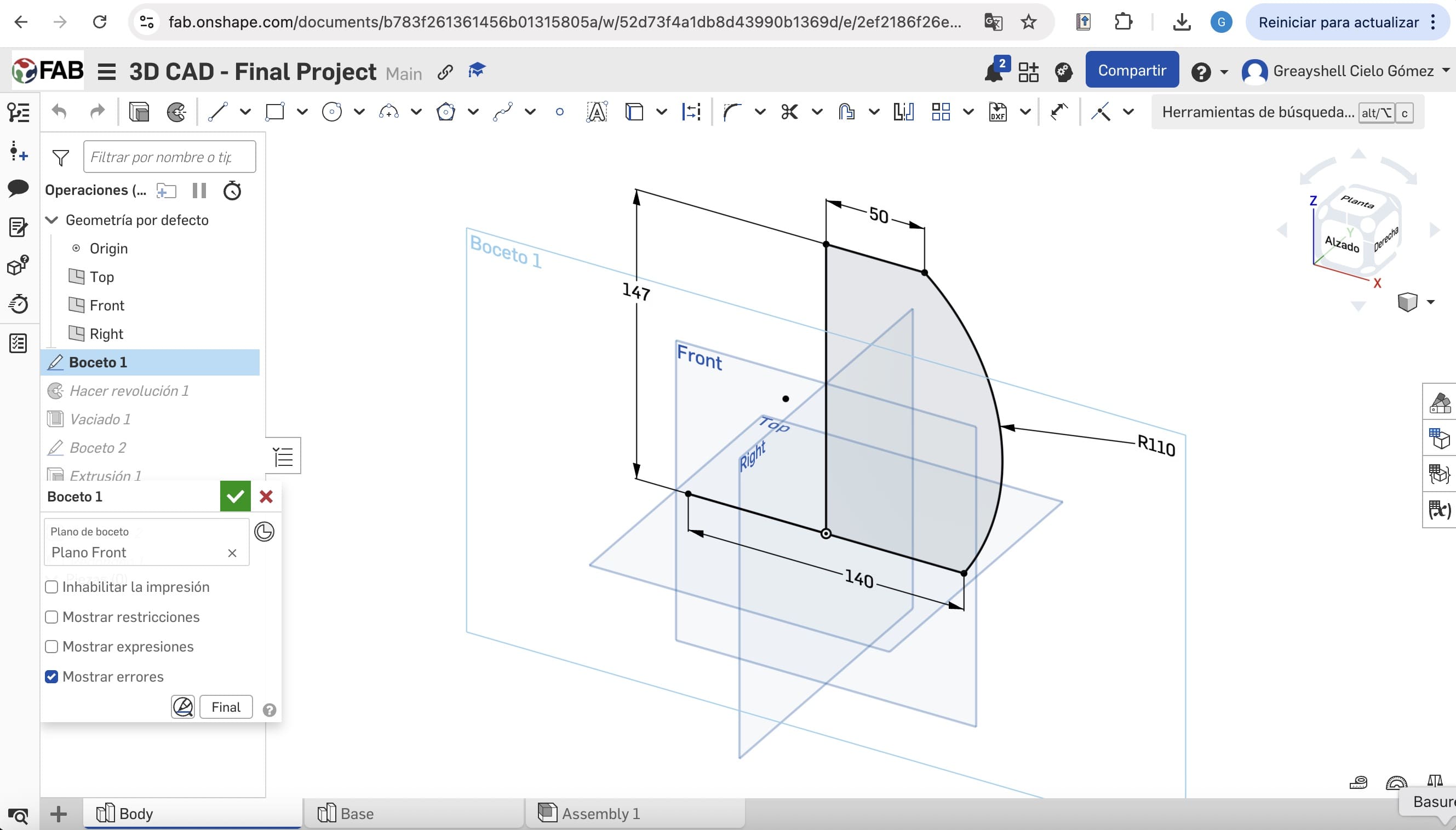
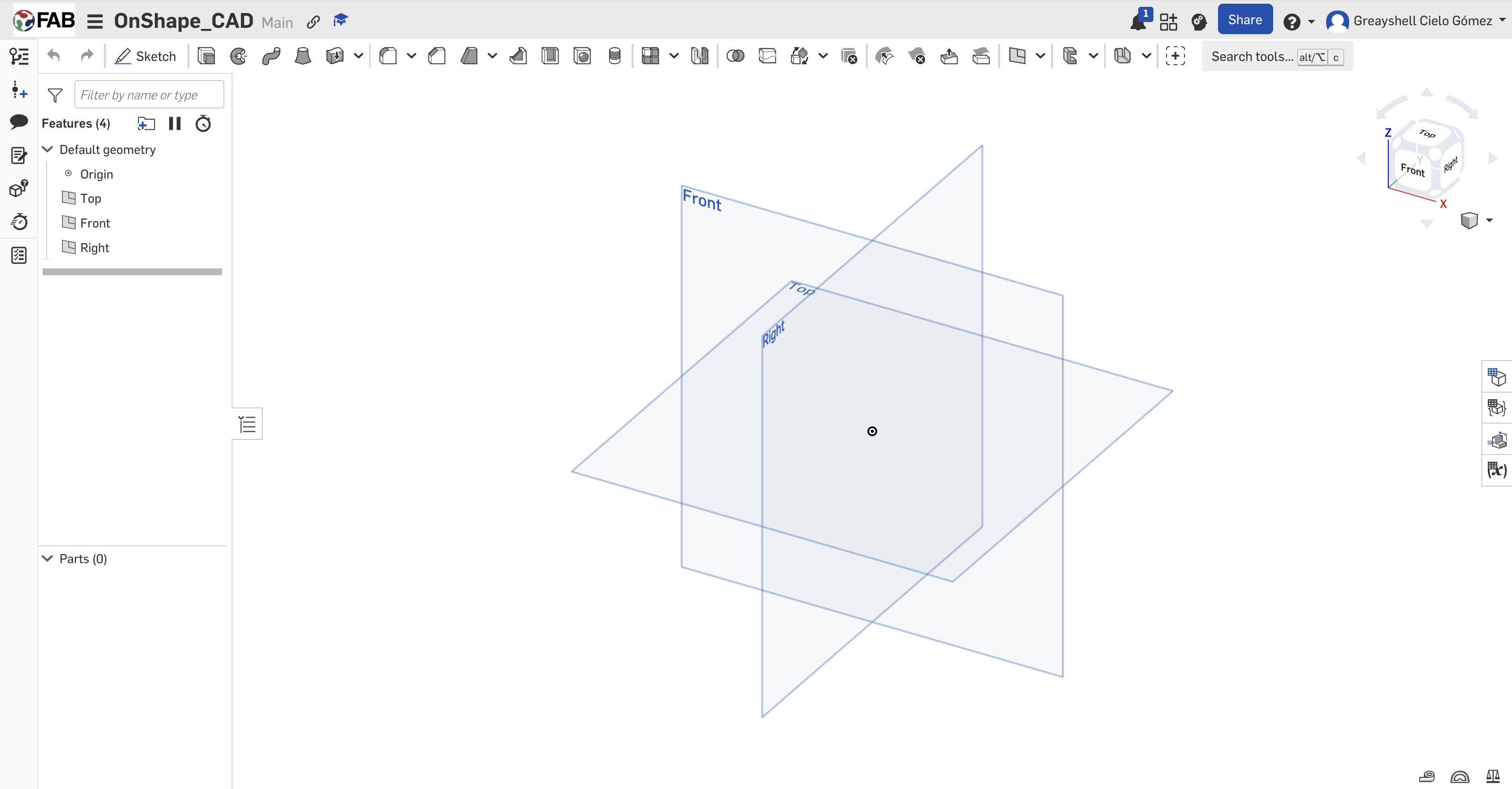
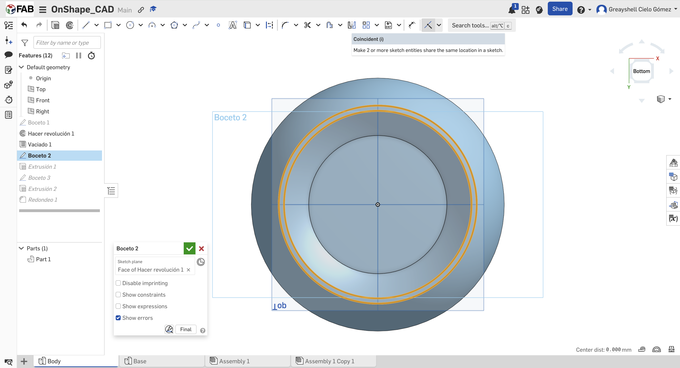
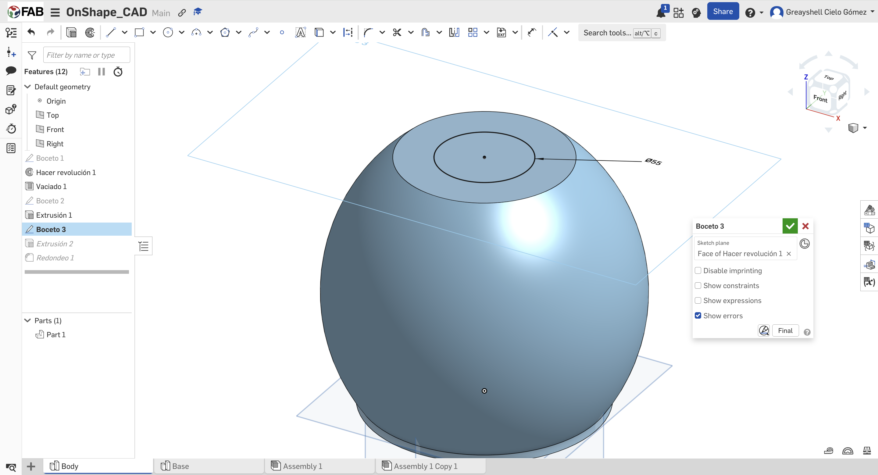
01. New Part Studio
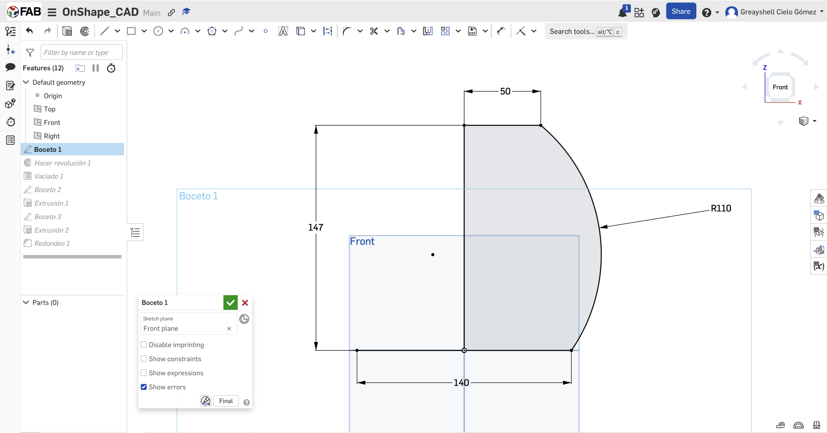
Defining initial constraints and 2D parametric geometry. Using tools such as: line, circle, arc position relationships.
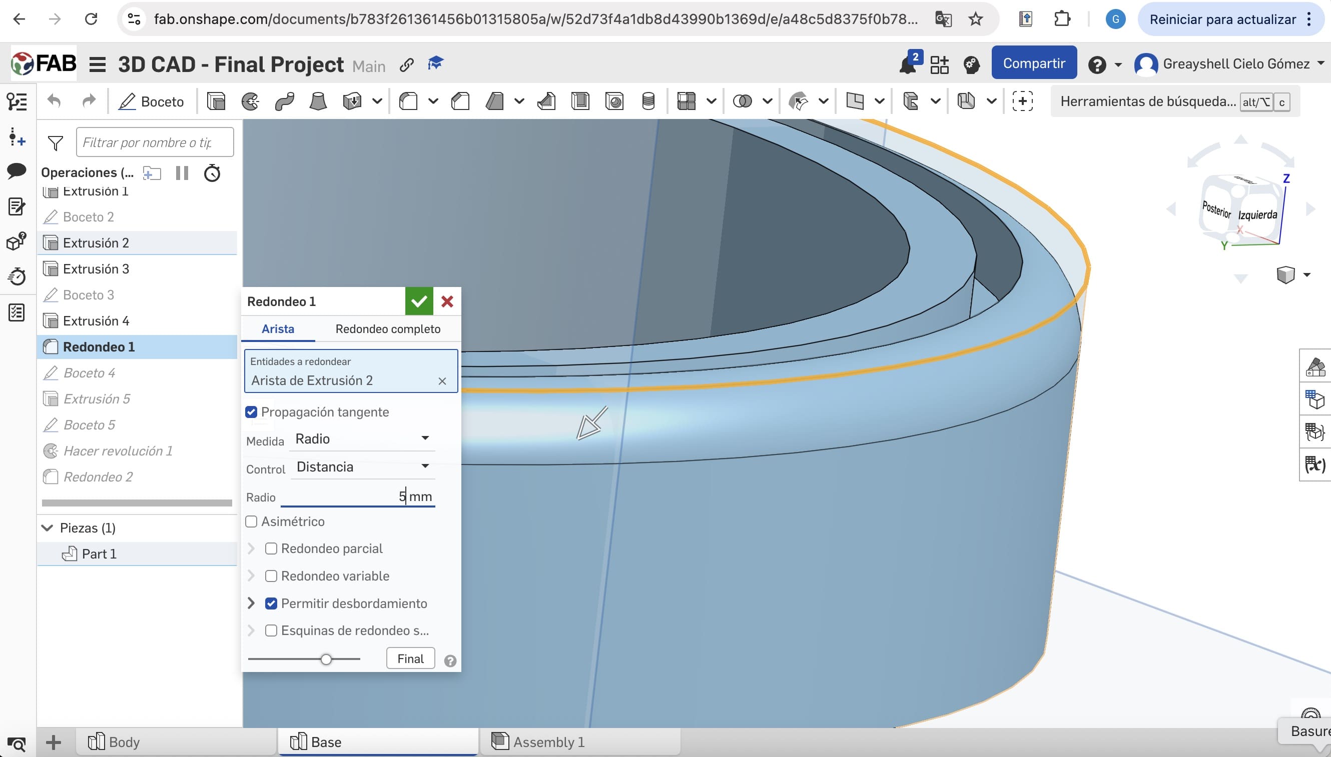
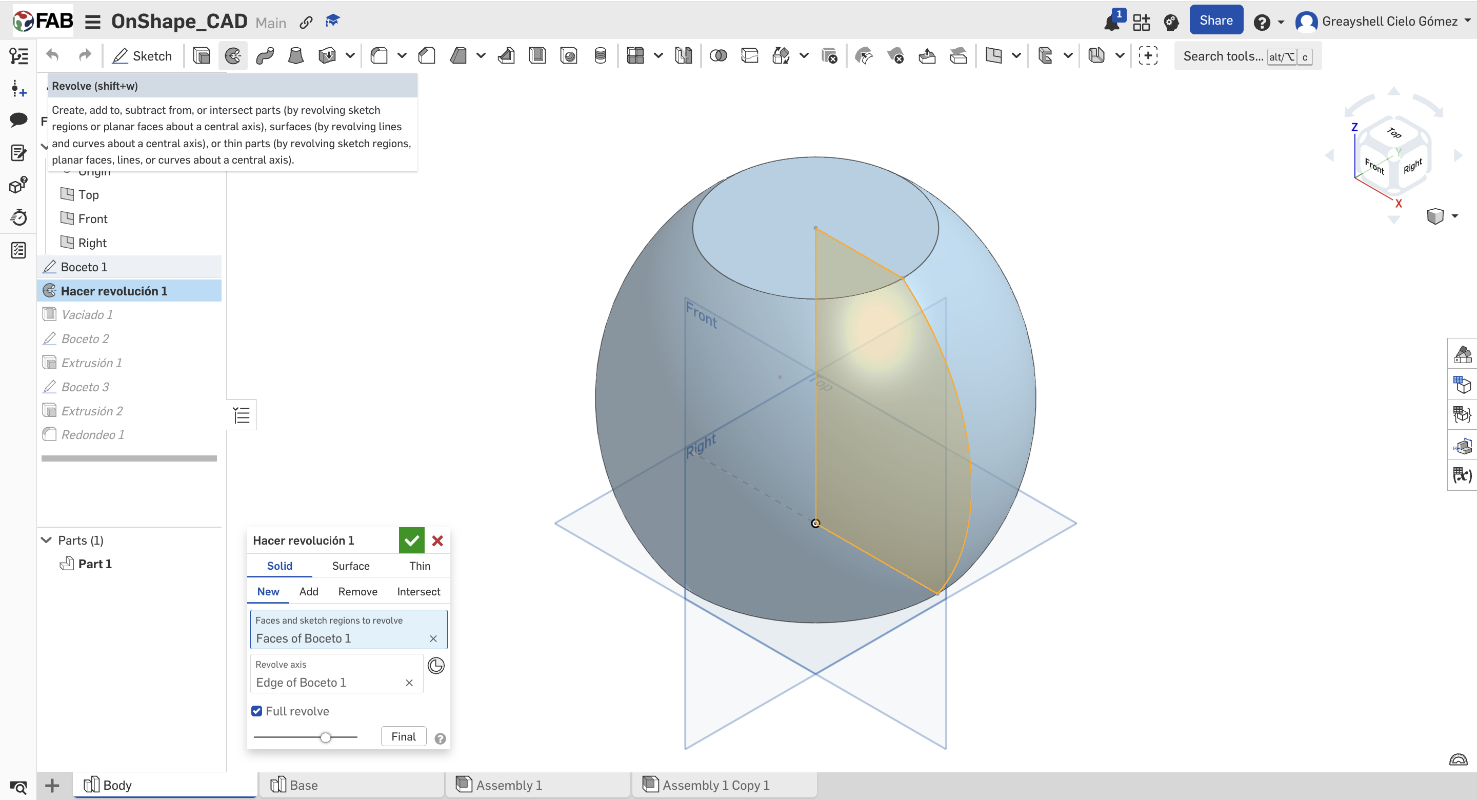
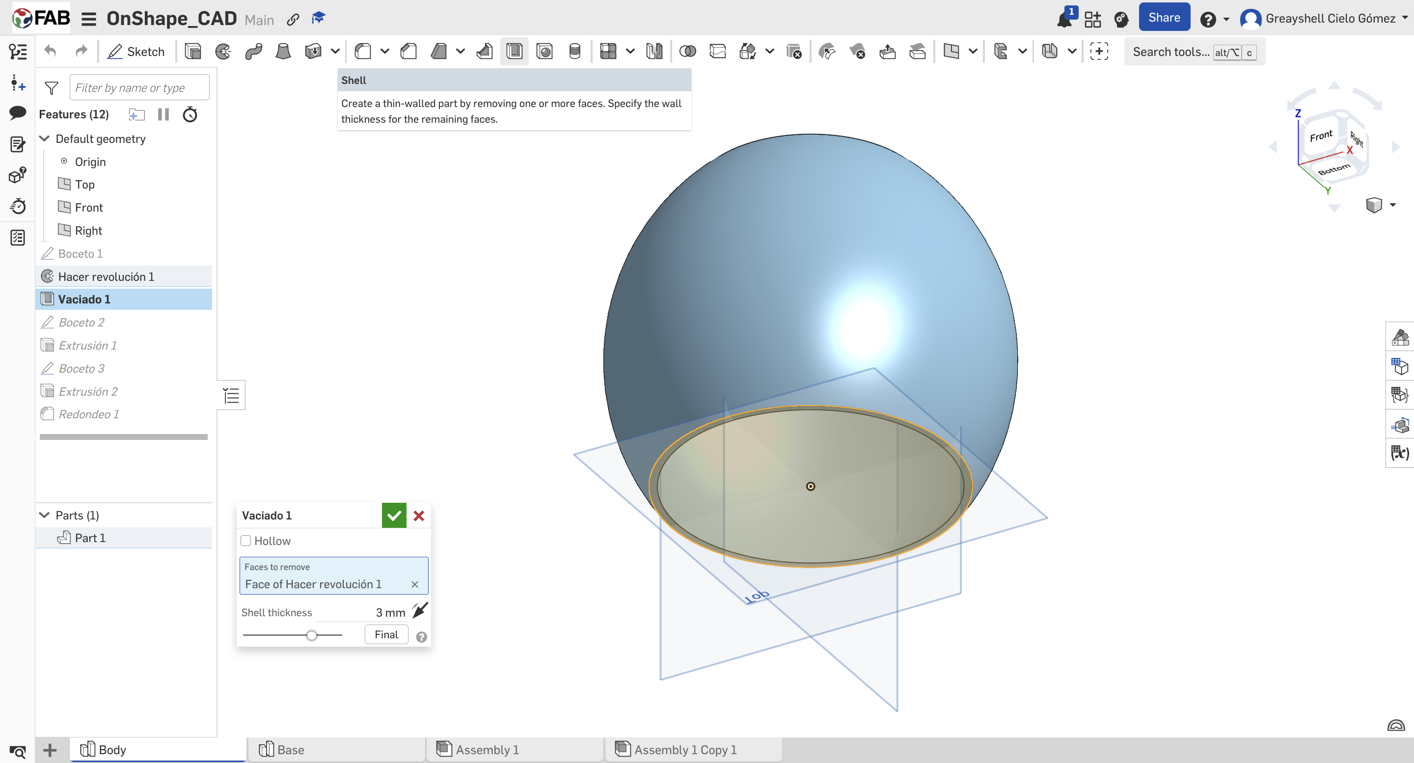
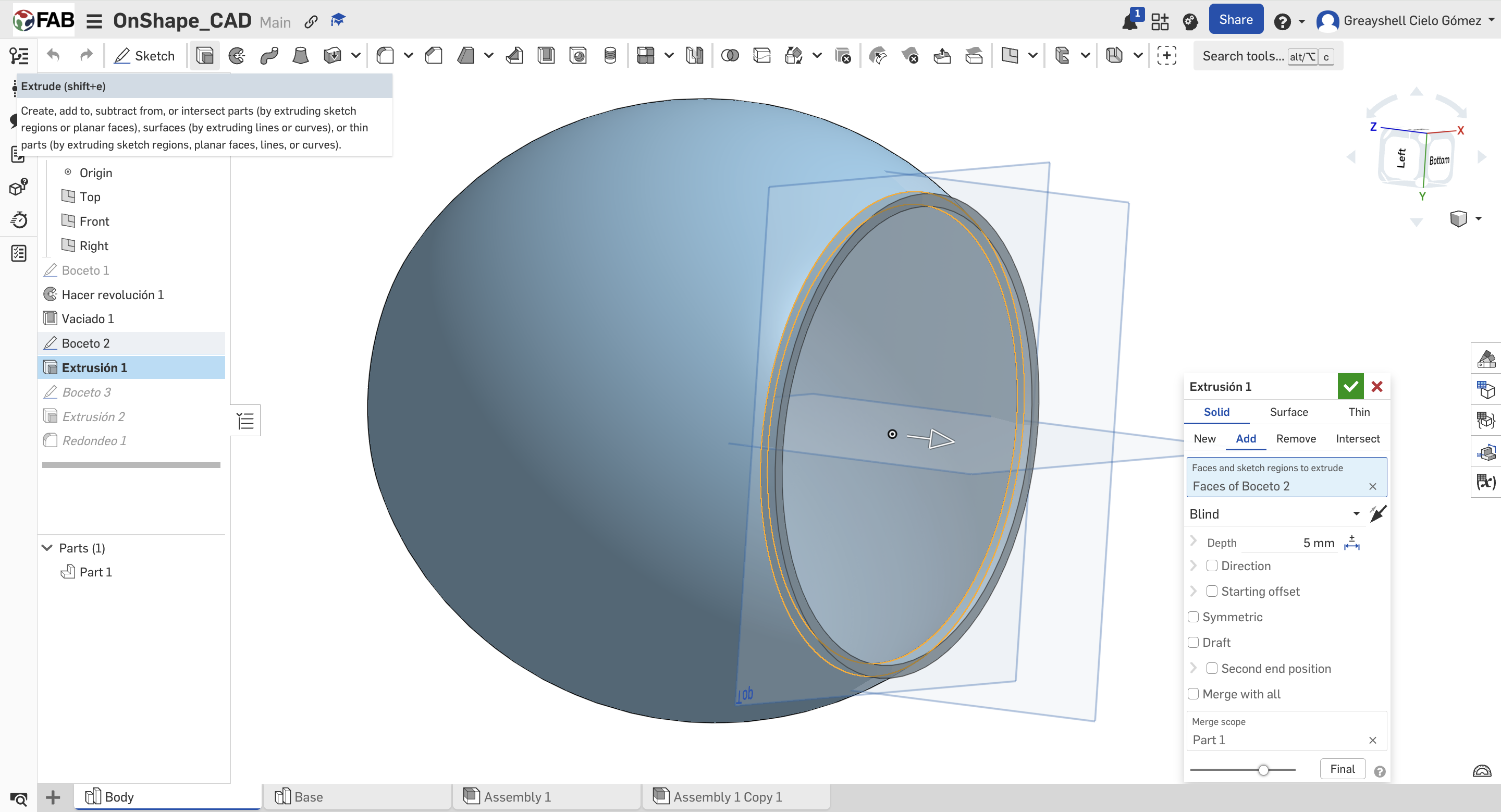
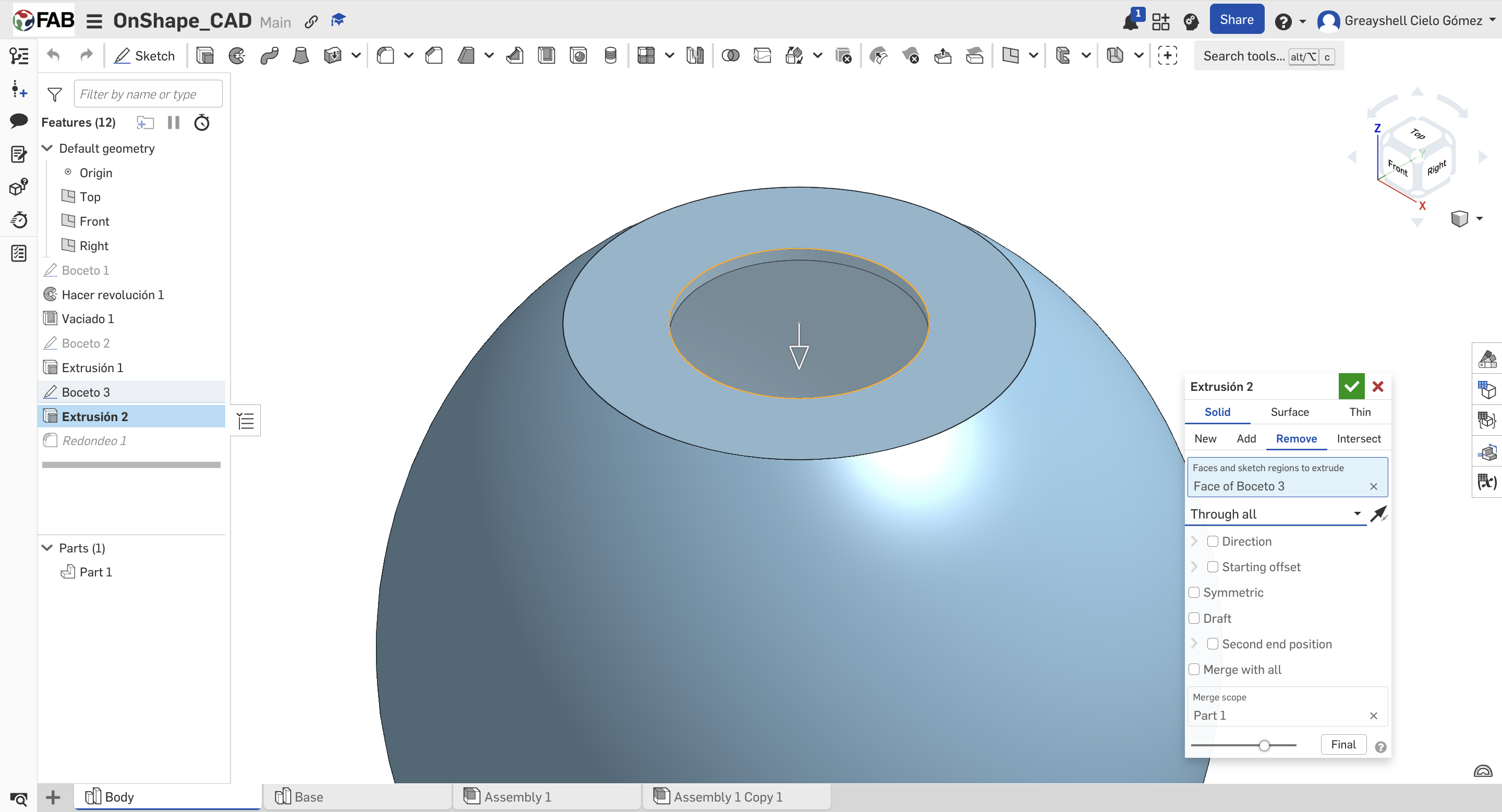
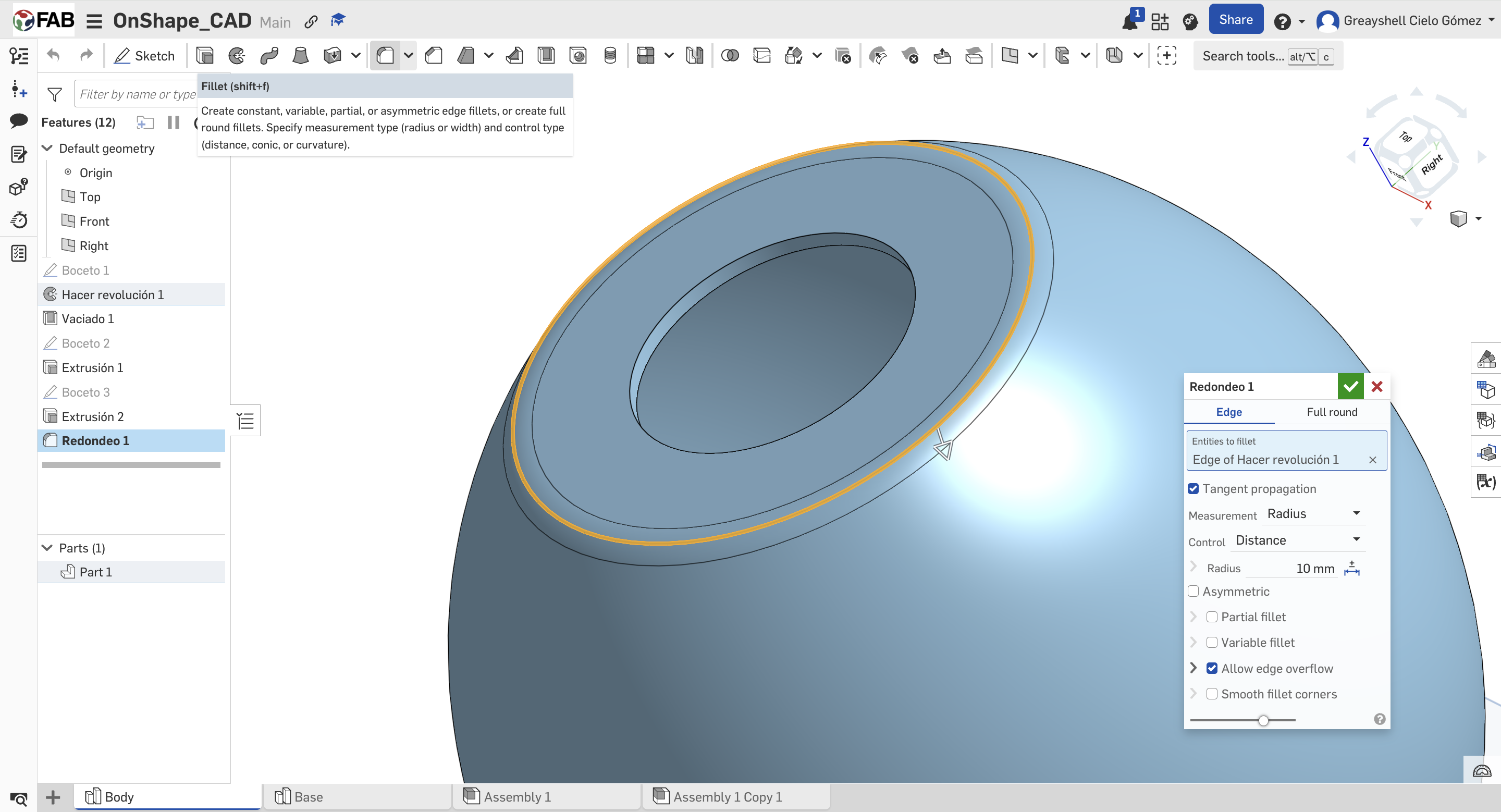
02. Main Operations
Applying extrusions and revolves to create solid parts. Applying Shell and Fillet operations to the base.
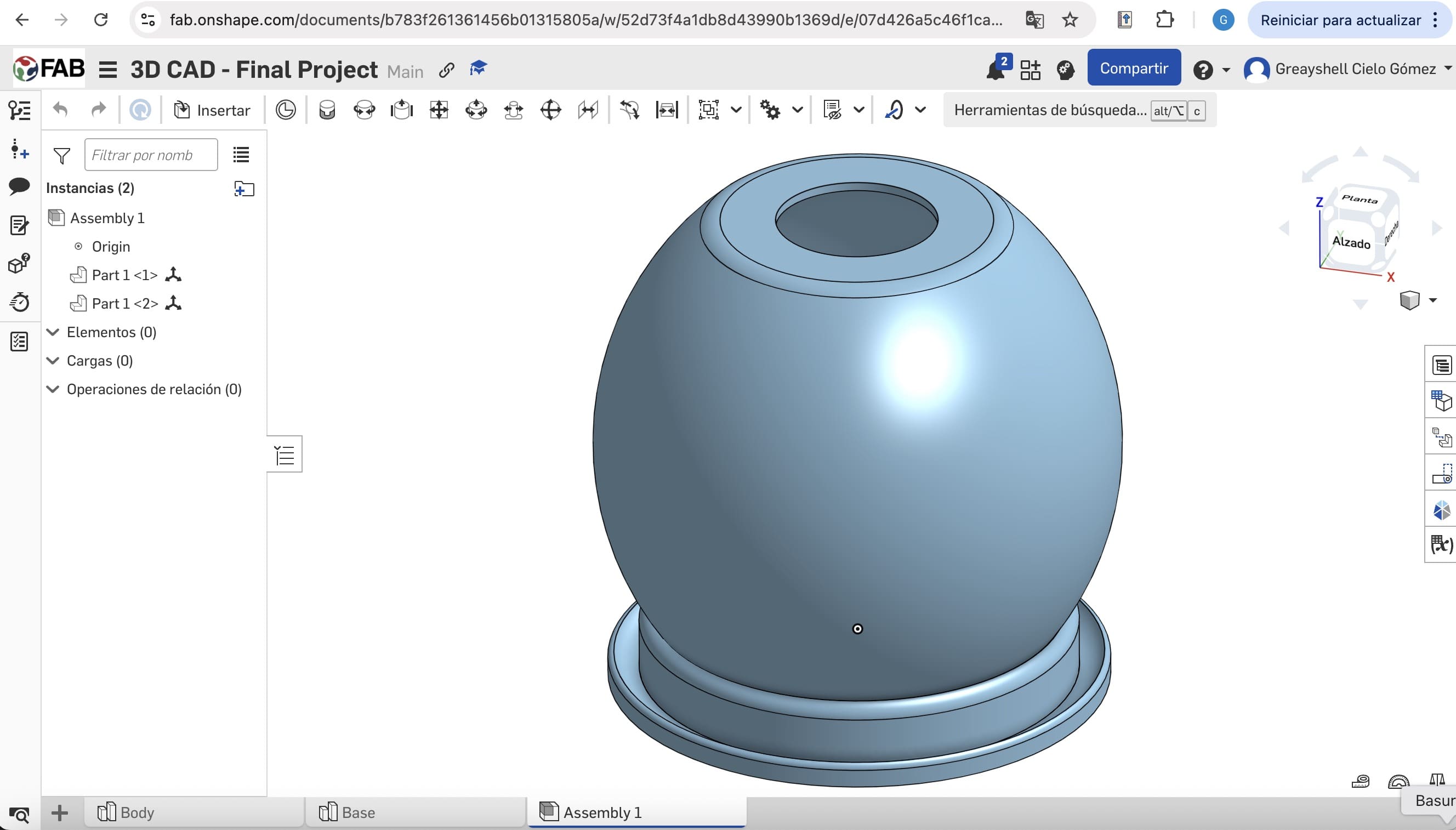
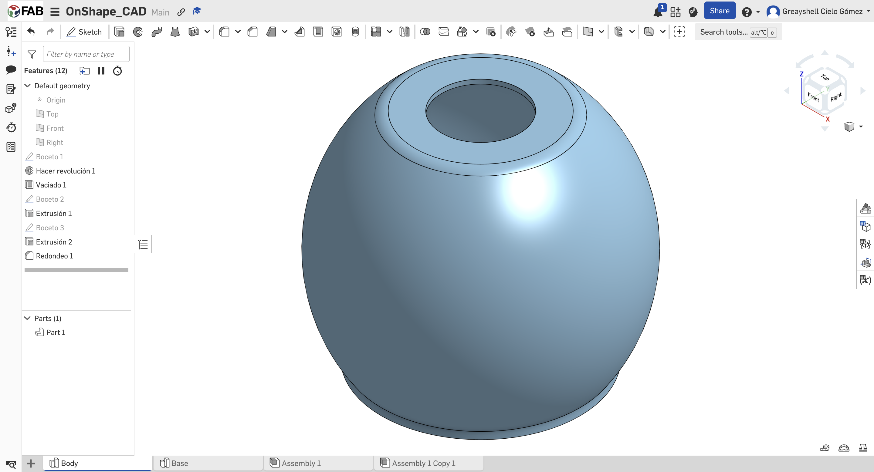
03. Final Assembly
Finalizing the Assembly by mating the base components to verify the fit and tolerances of the device.

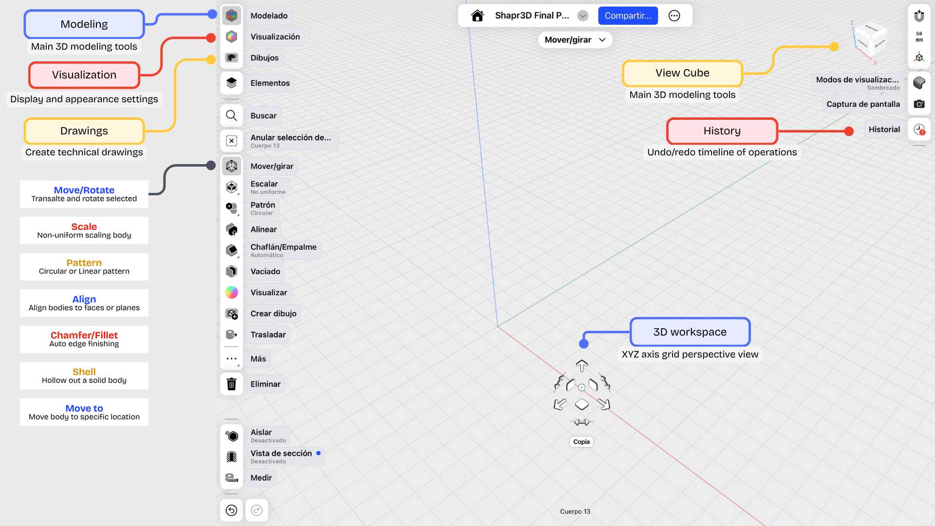
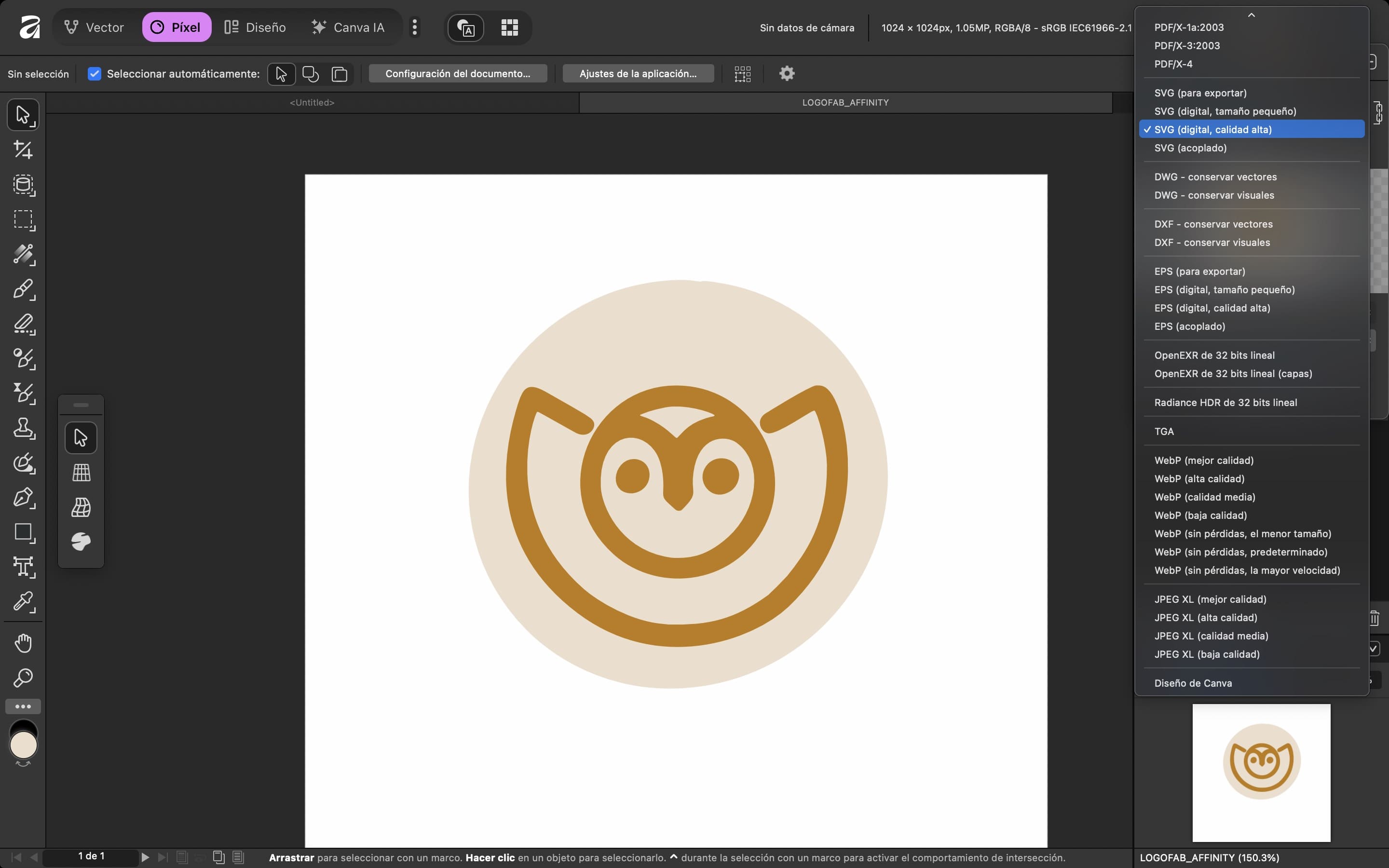
Shapr3D is a 3D modeling application designed for a fluid and mobile workflow. It’s primarily built for use on iPads and touch devices, allowing for a more direct and natural interaction with the design. It enables the creation of three-dimensional models and structural plans, as well as the visualization of materials and finishes on the final parts. It’s an excellent tool for rapid prototyping and bringing ideas to life quickly.
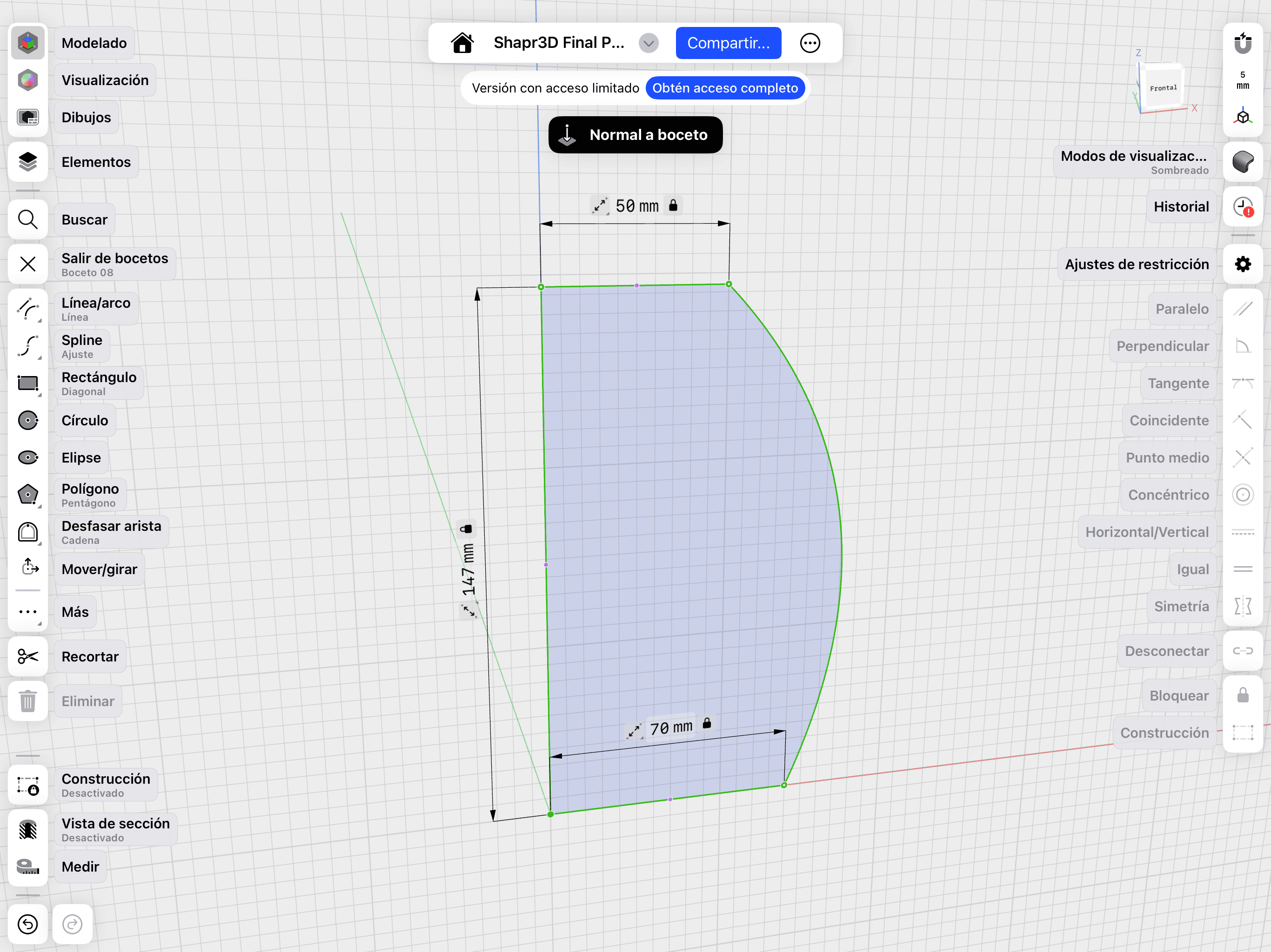
01. Mobile Sketching
Using touch interface for organic shapes and quick drafts.
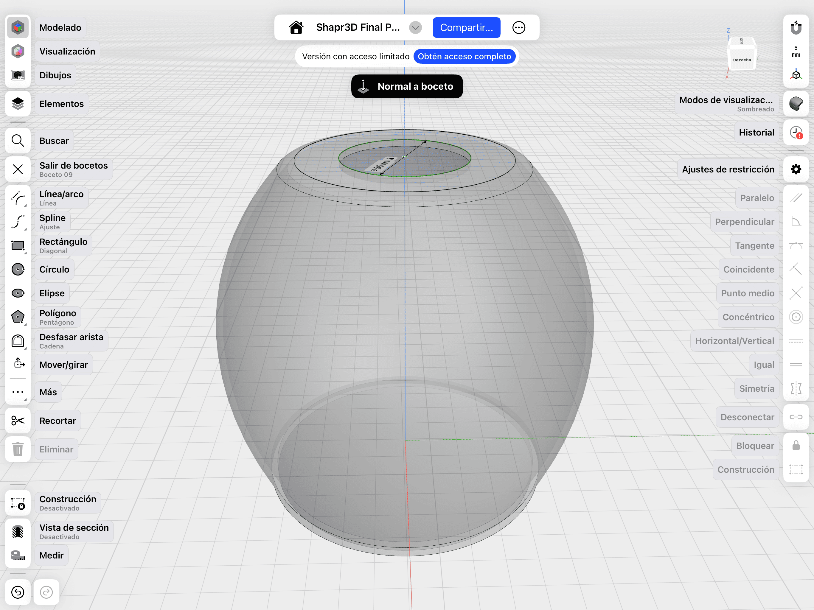
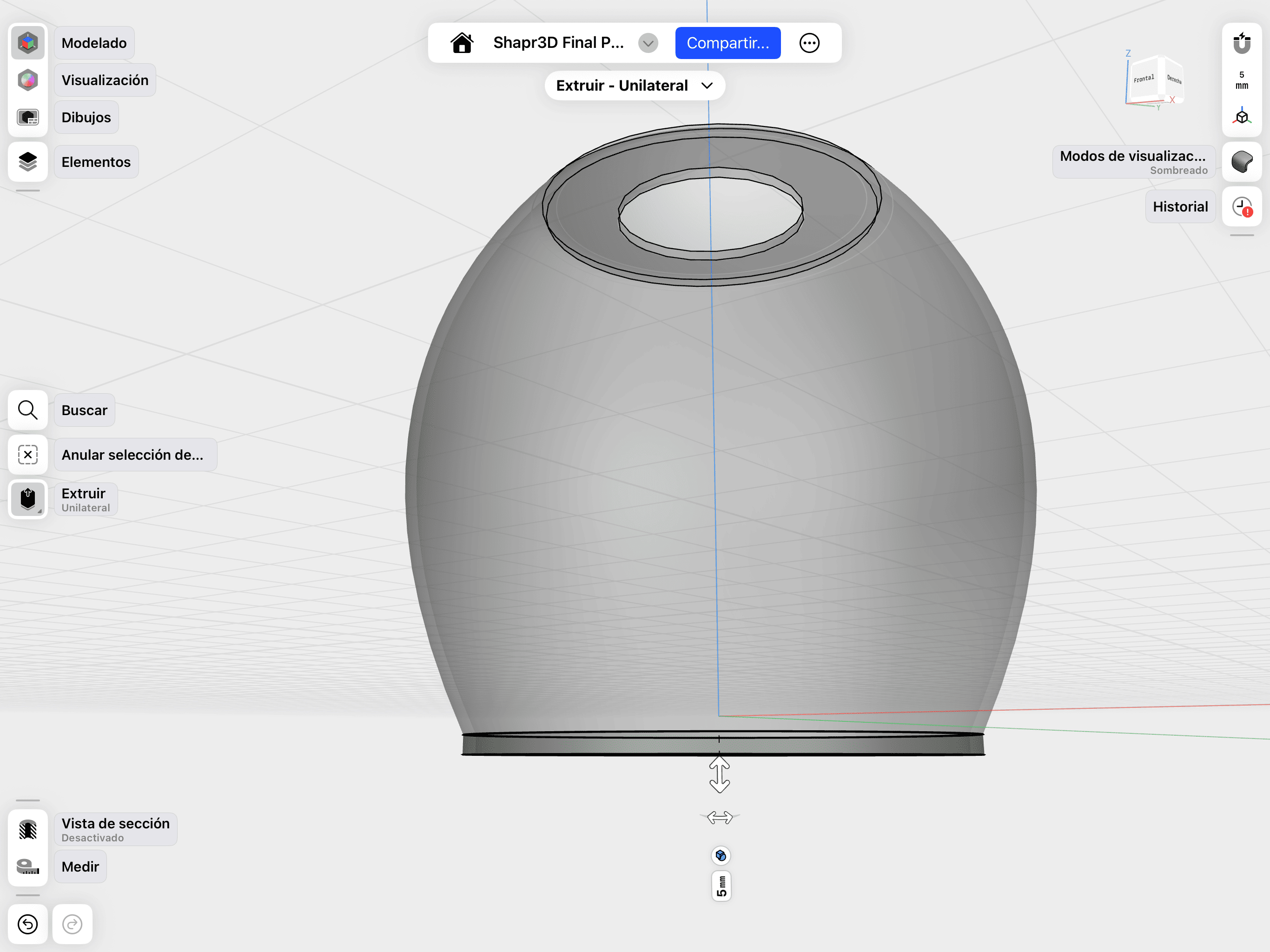
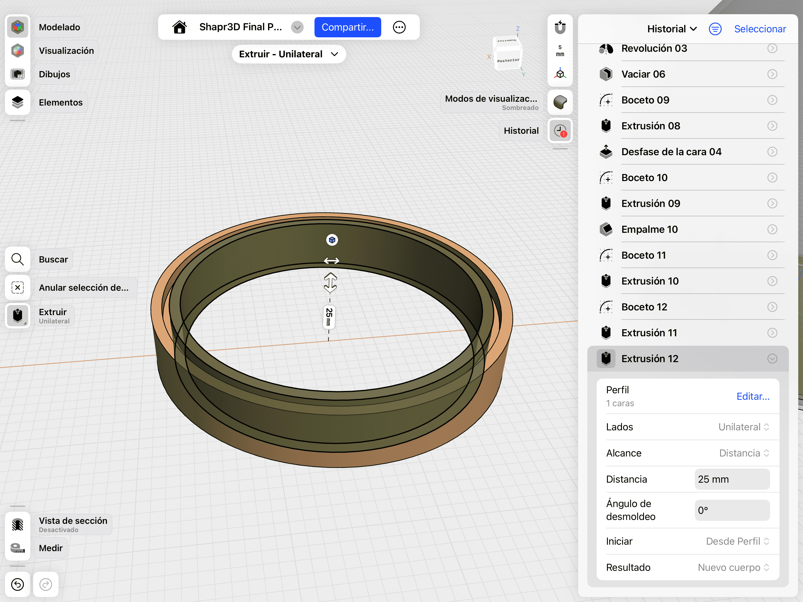
02. Revolve & Cut
Applying the Revolve tool to the profile sketch and executing a boolean cut for the top circular opening.
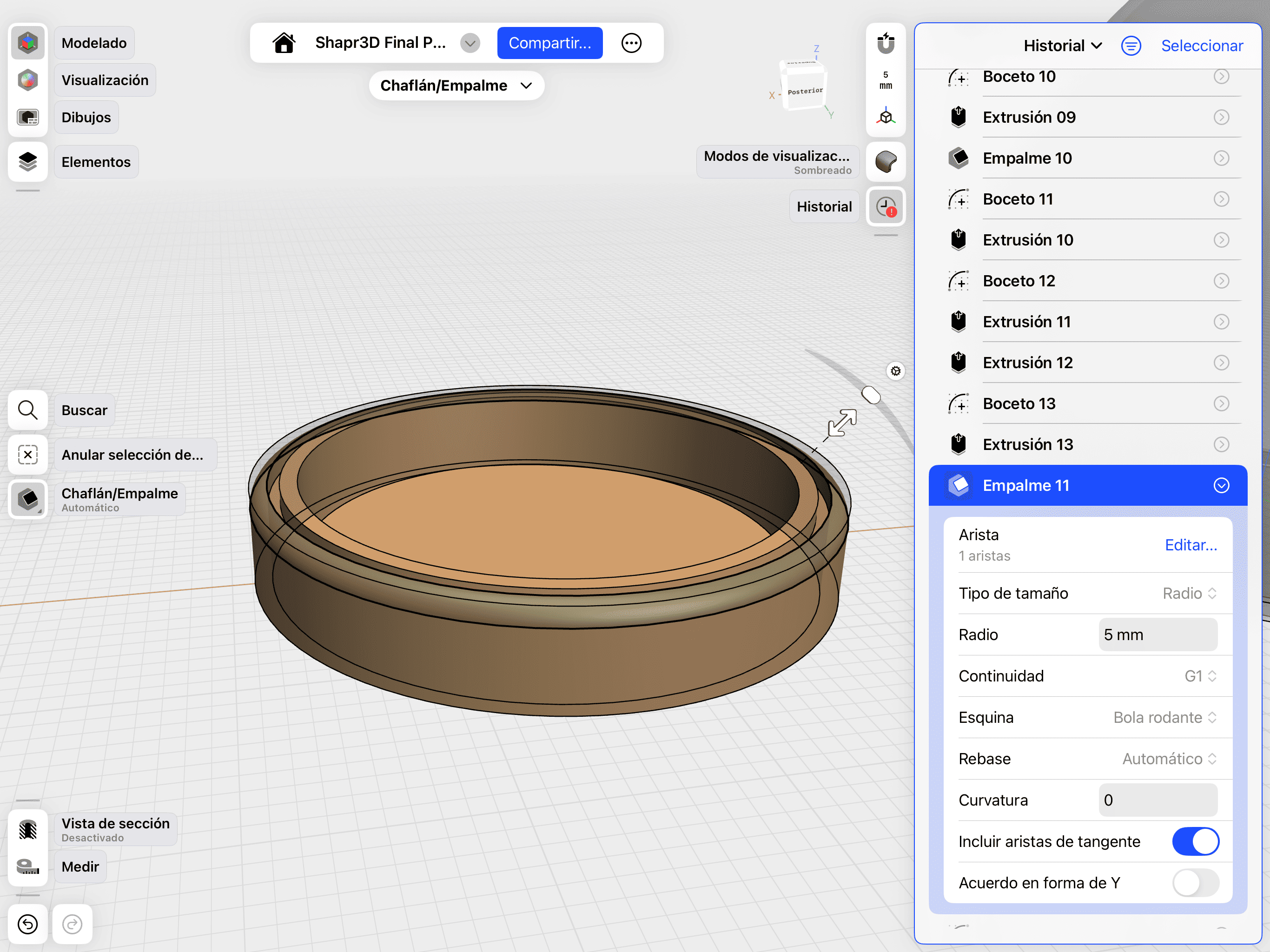
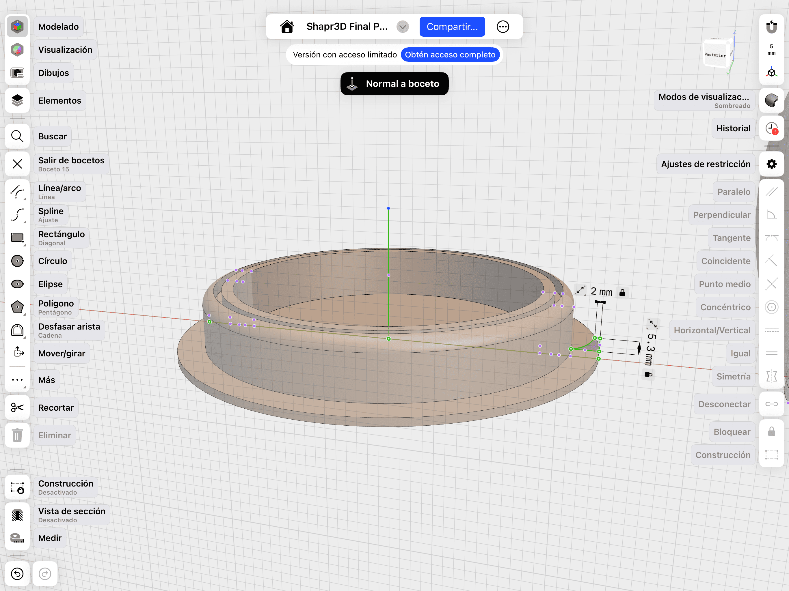
03. Fillet & Ergonomics
Adding Fillets for a more ergonomic, professional and aesthetic finish.
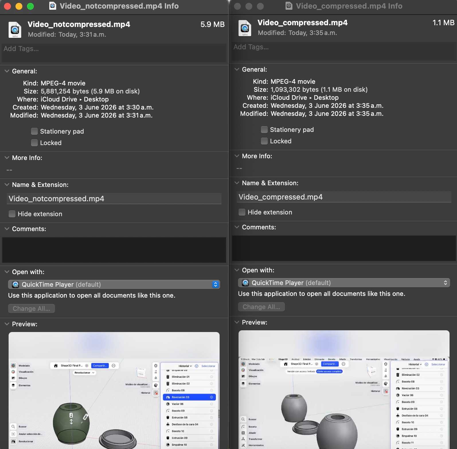
Final Visualization
Documentation of the rendering process in Shapr3D to visualize materials, lighting, and final finishes of the device.
This step was very simple, since all I had to do was go to "visualization", and in the window that opens, look among the different materials for the one that best suits my design, and drag it onto the object.
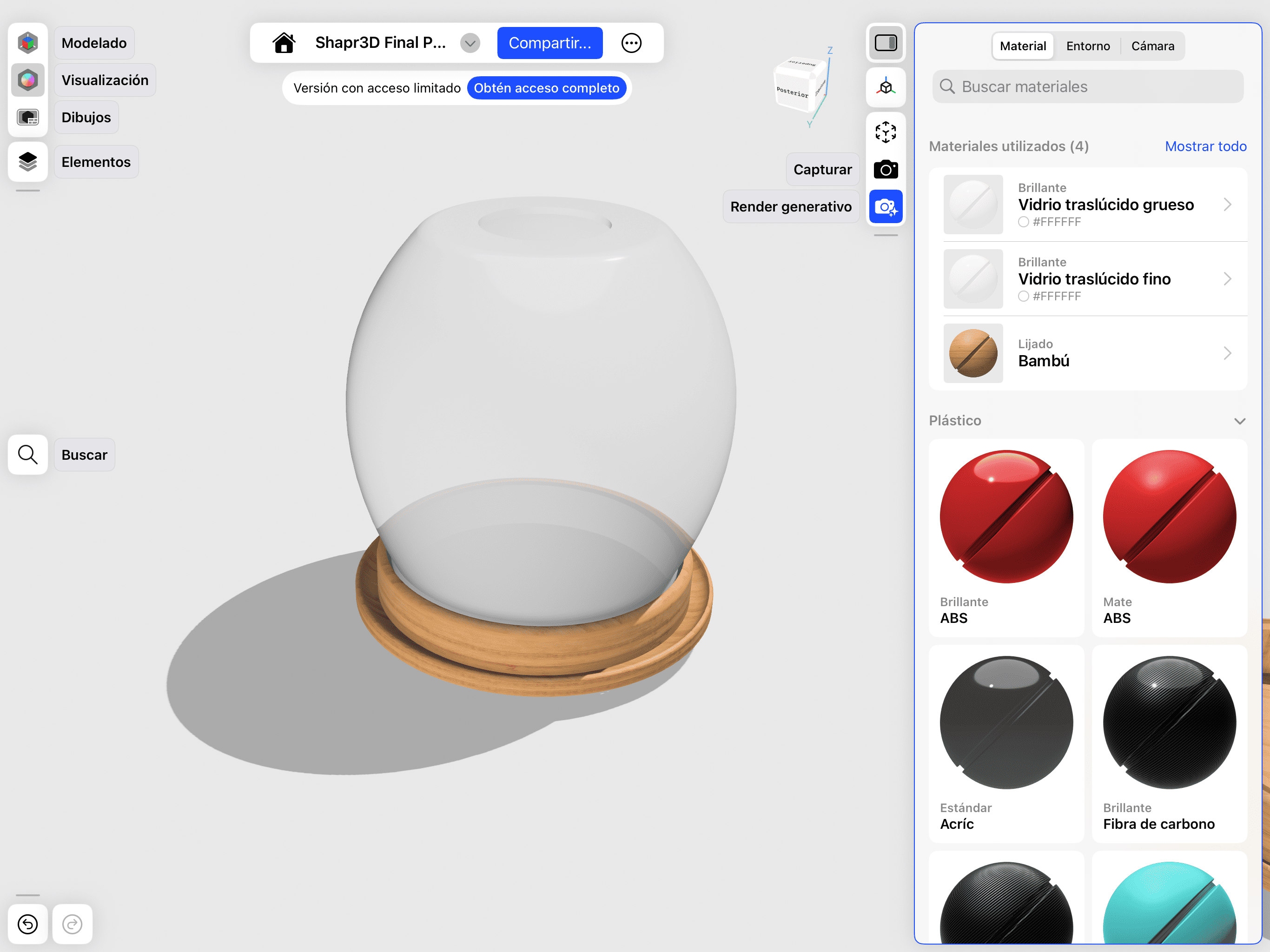
01. Material Application
Swipe to see the different materials and drag that one to the object.
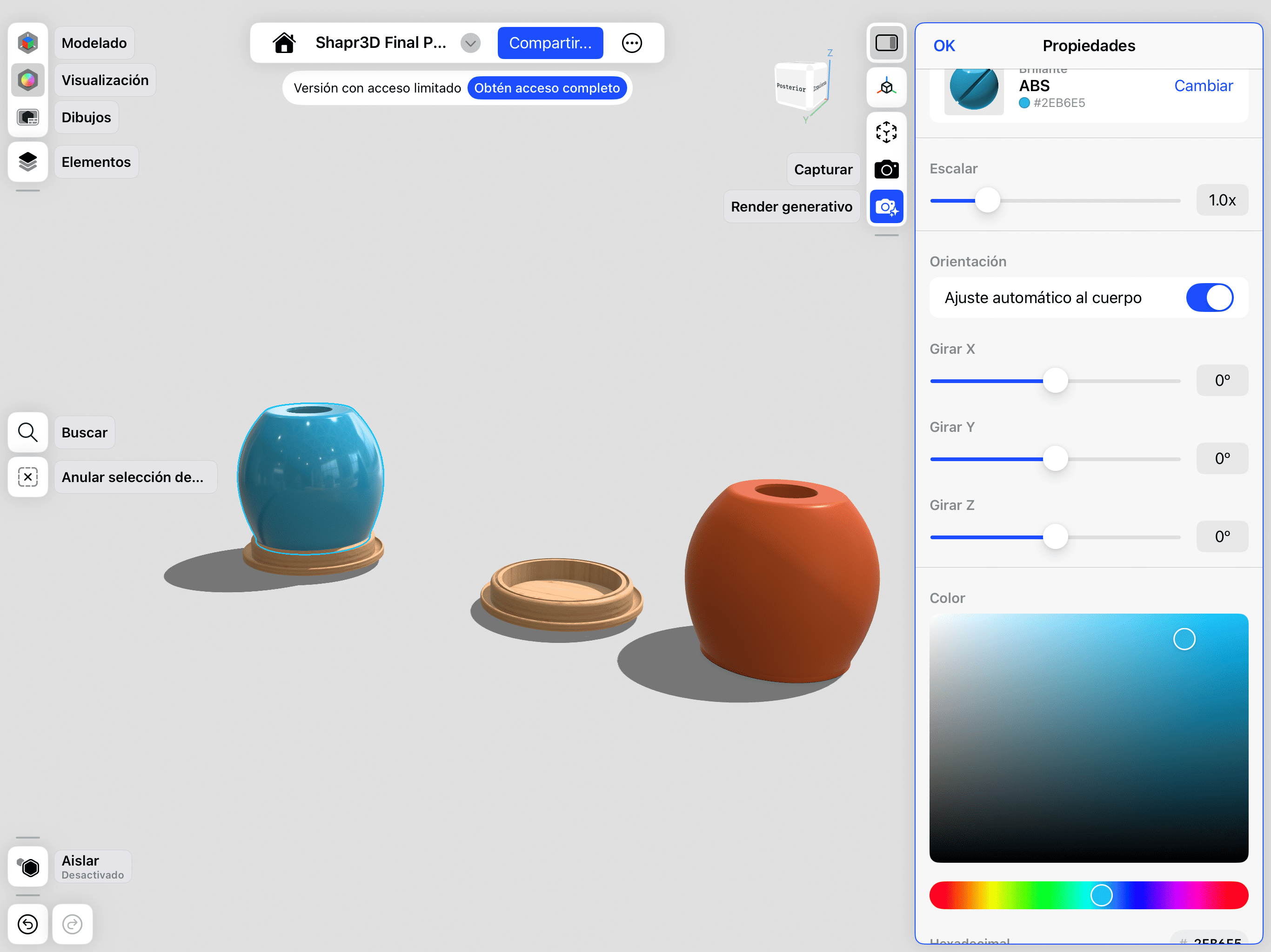
02. Setup
You can configure the light, tone and color of the material by clicking on it.

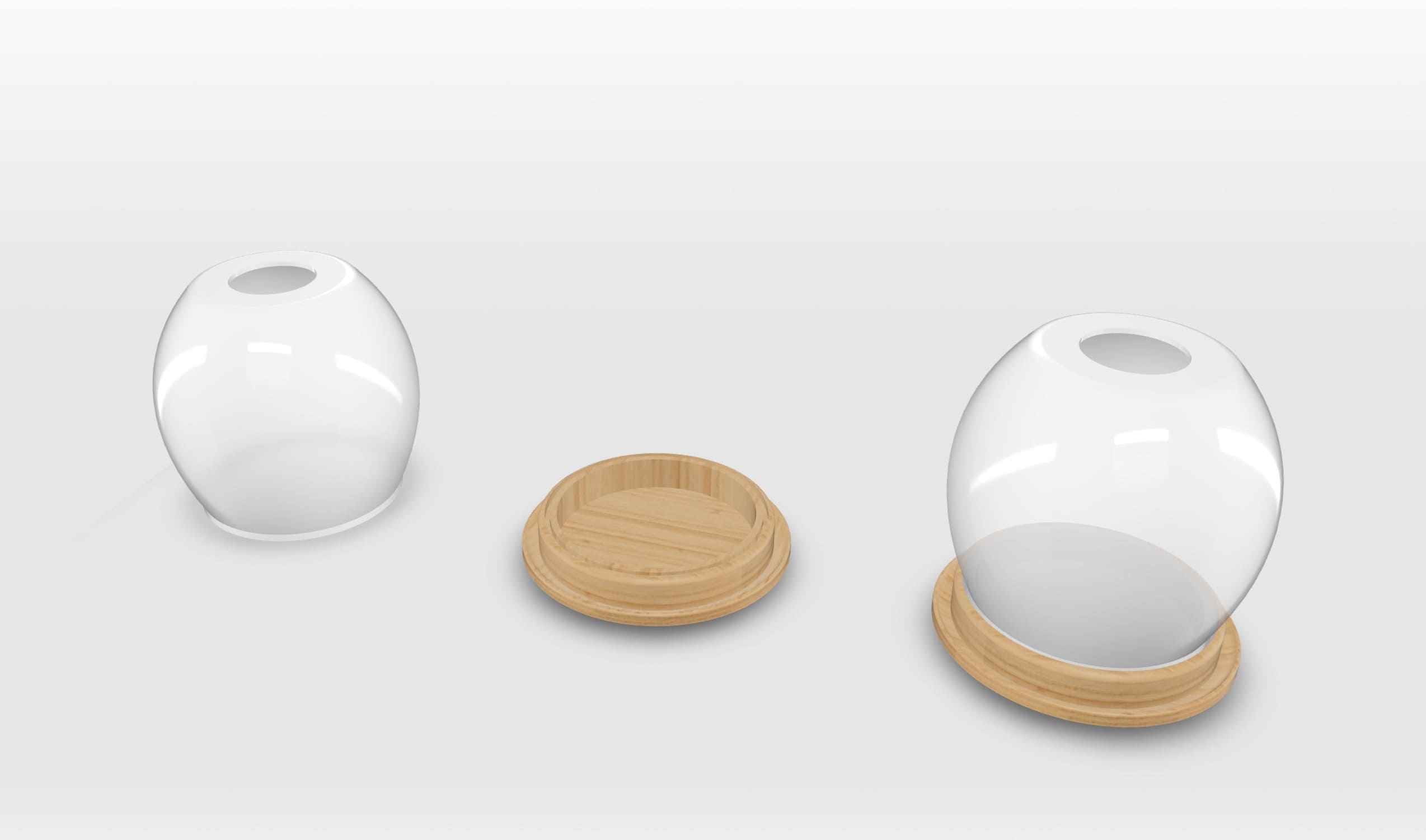
03. High-Quality Render
The final visualization of the proposed project.
Design Files
In this section, you can find the downloadable source files for the 3D models developed during this week.
OnShape Export
STEP/STL files for the main assembly and electronics base.
02. Shapr3D Model
Native and high-fidelity 3D files for the outer casing.
03. Project Bundle
Complete documentation and optimized mesh files for fabrication.