Week 3. Computer-Controlled Cutting

The Shadow Box

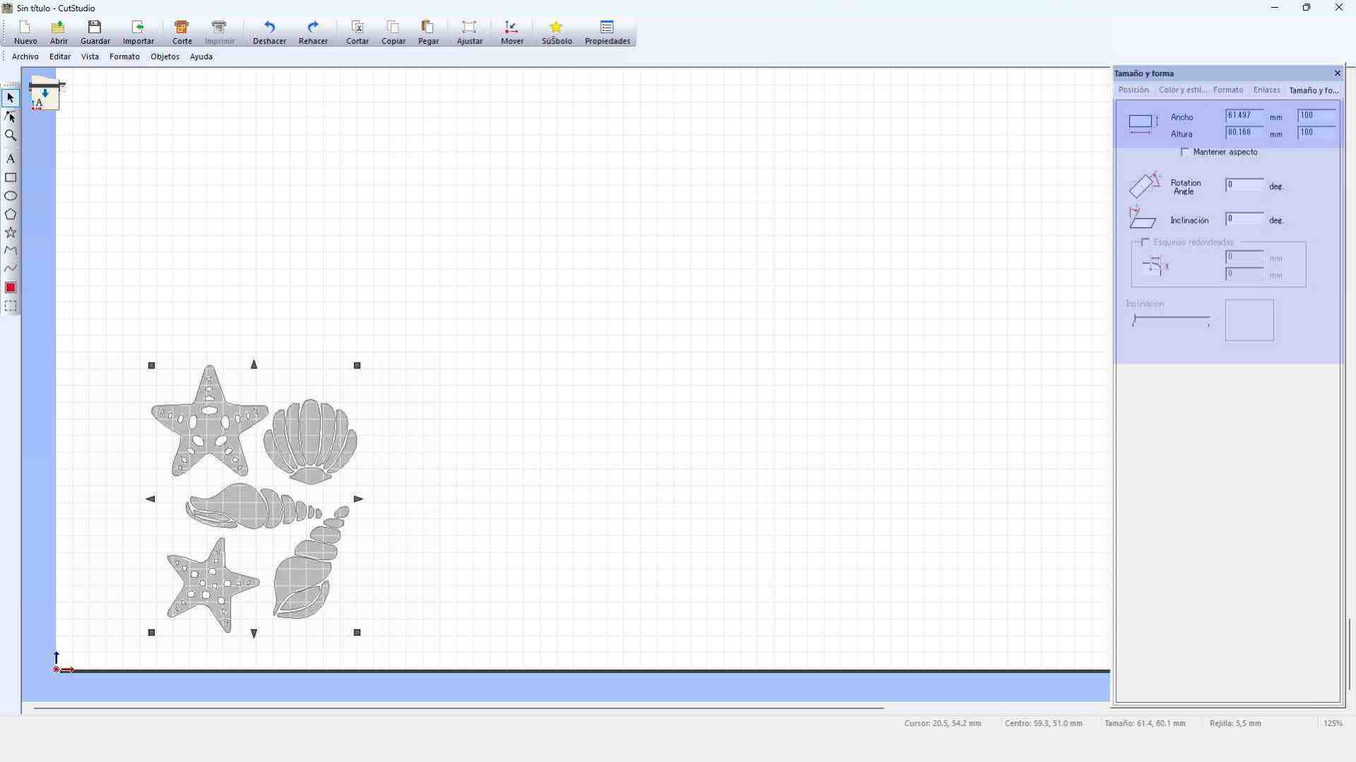
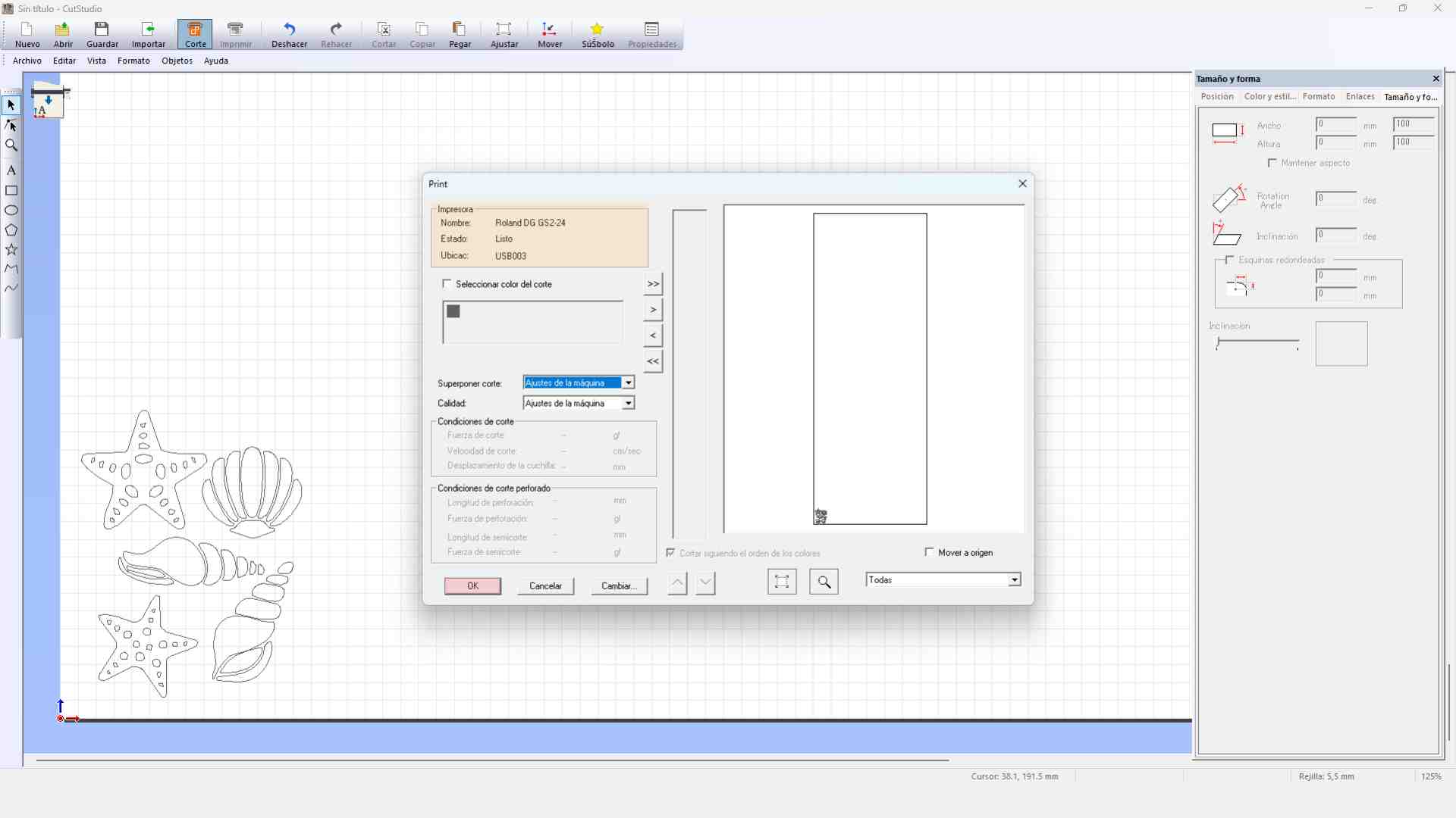
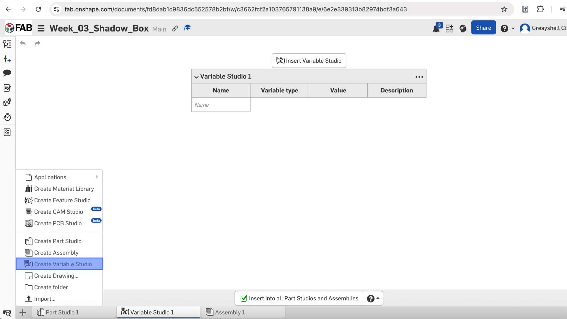
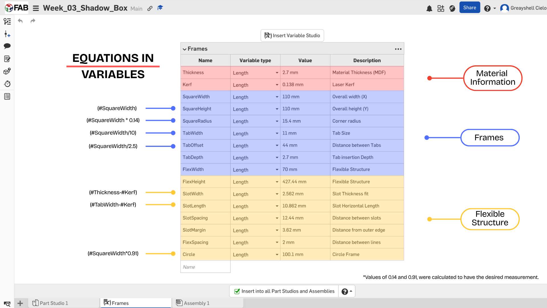
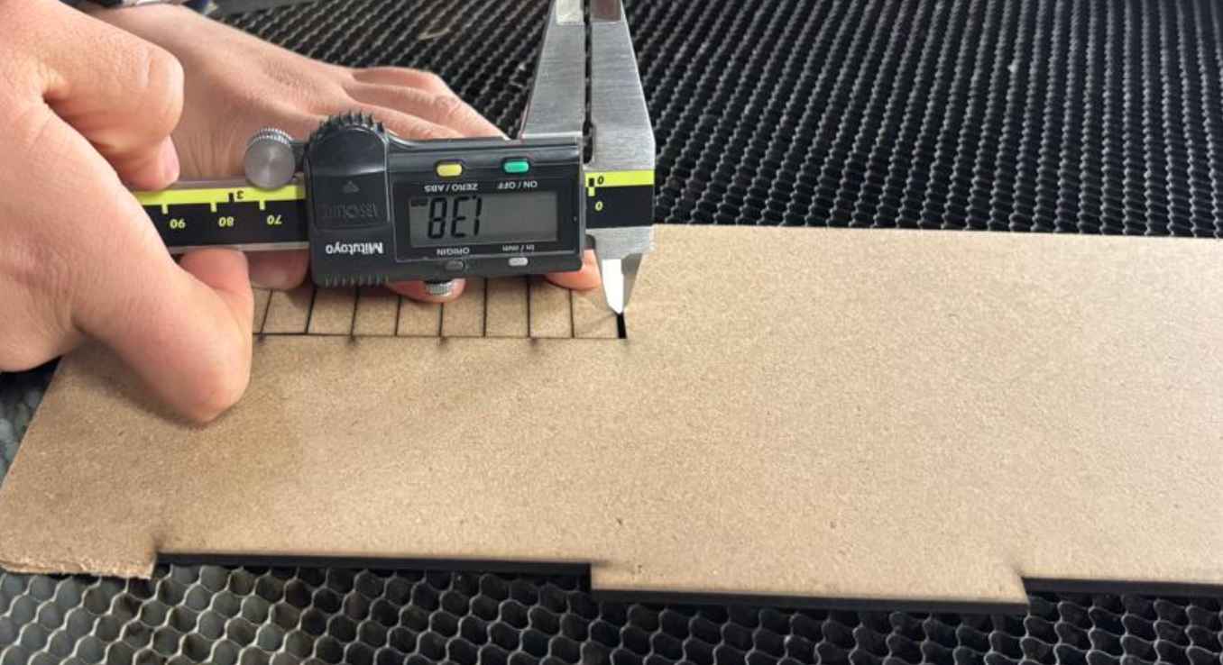
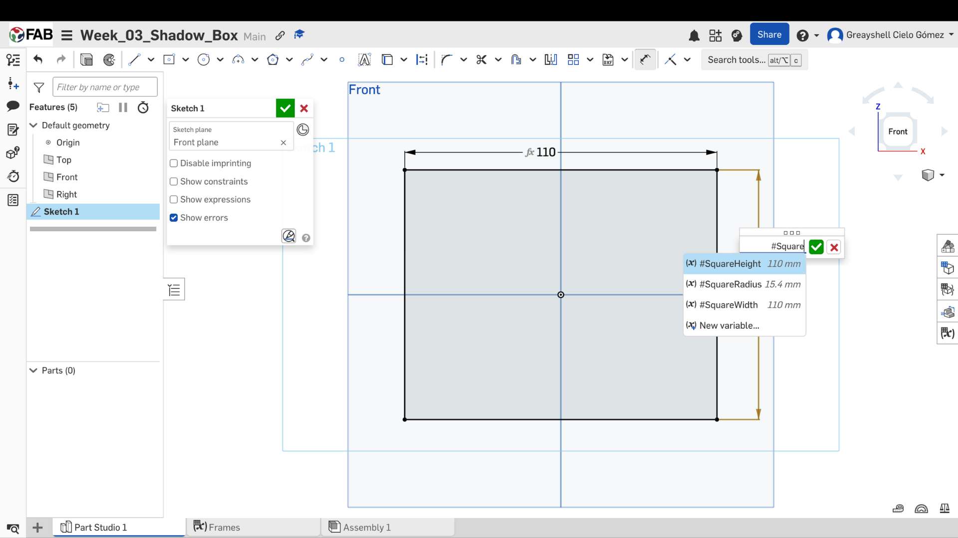
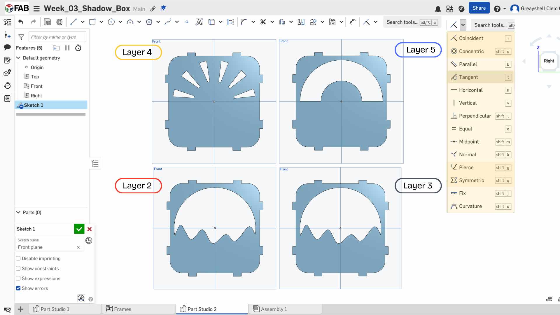
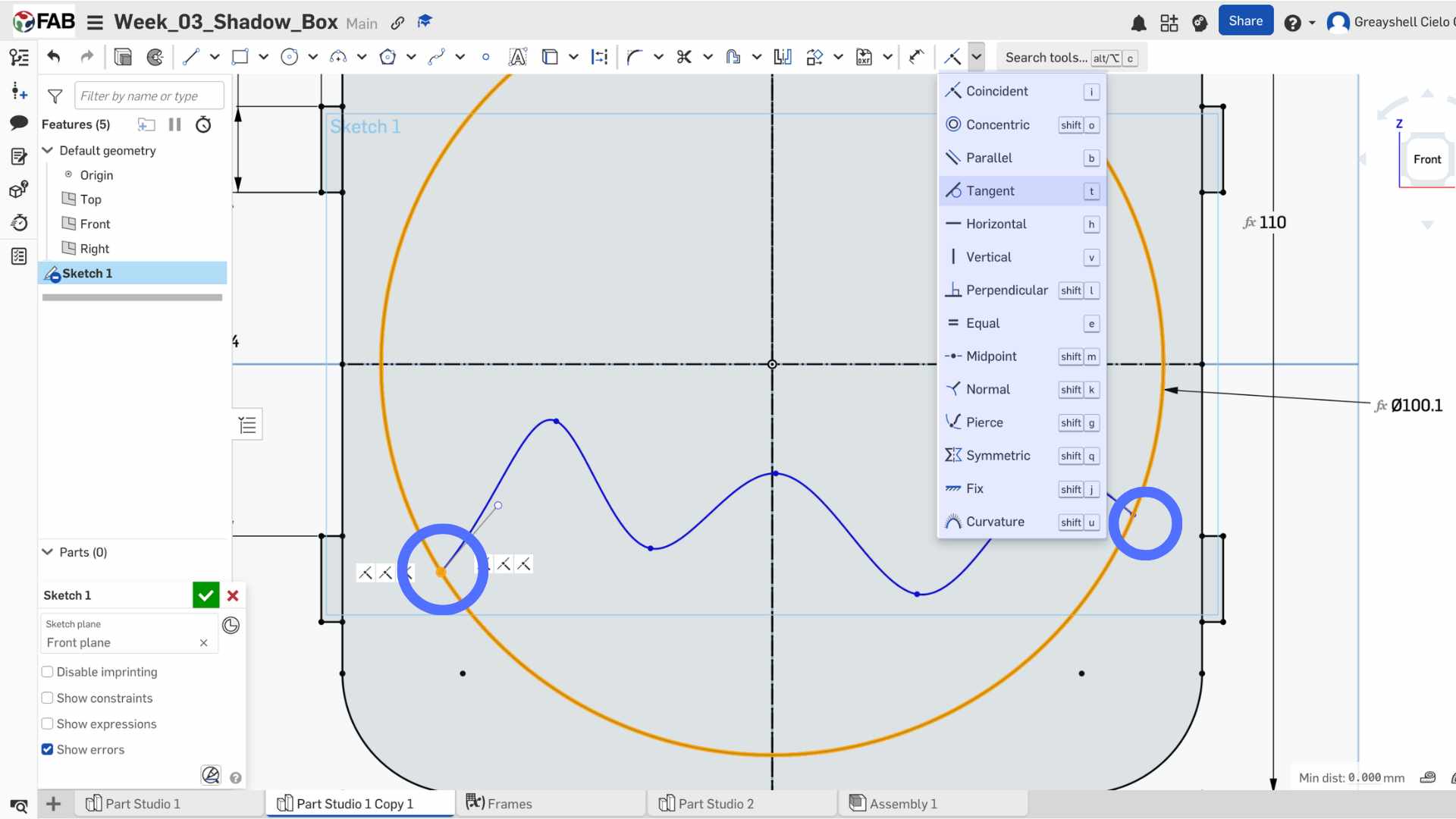
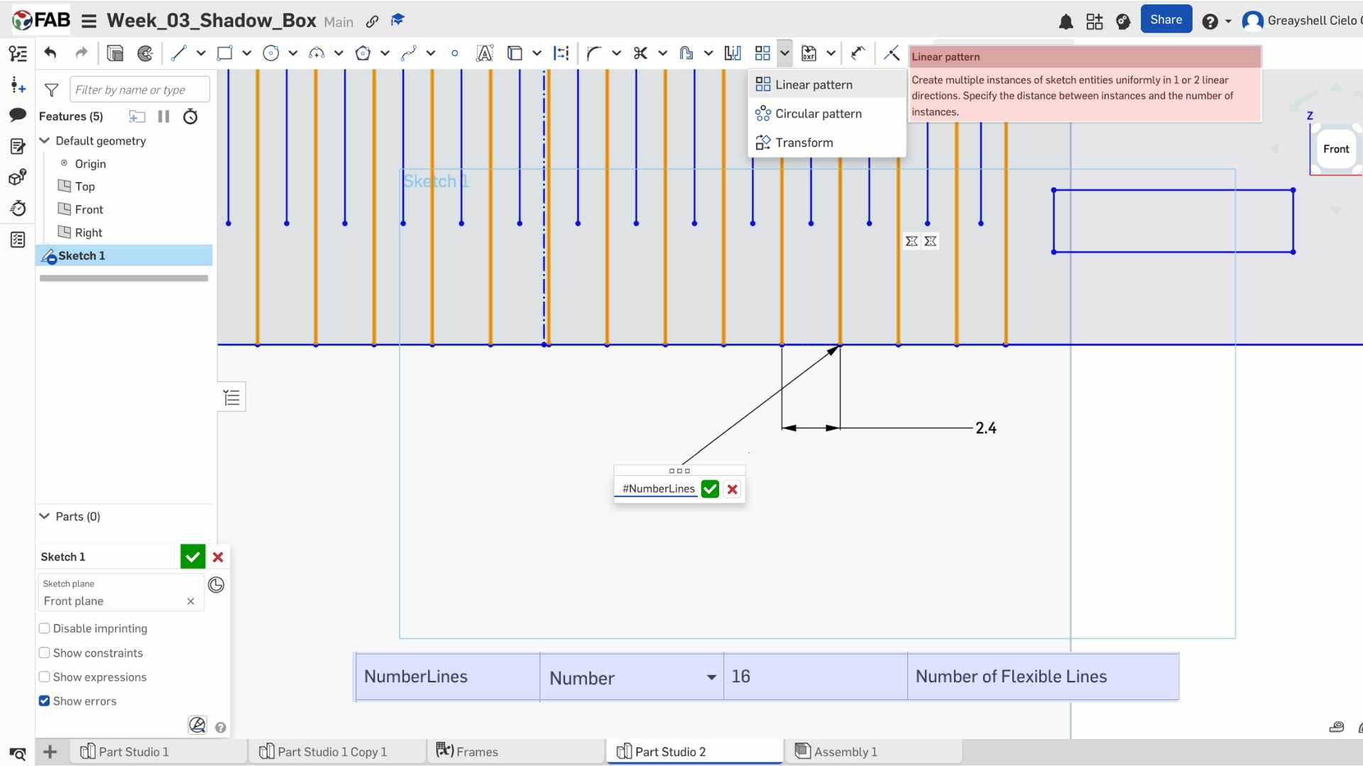
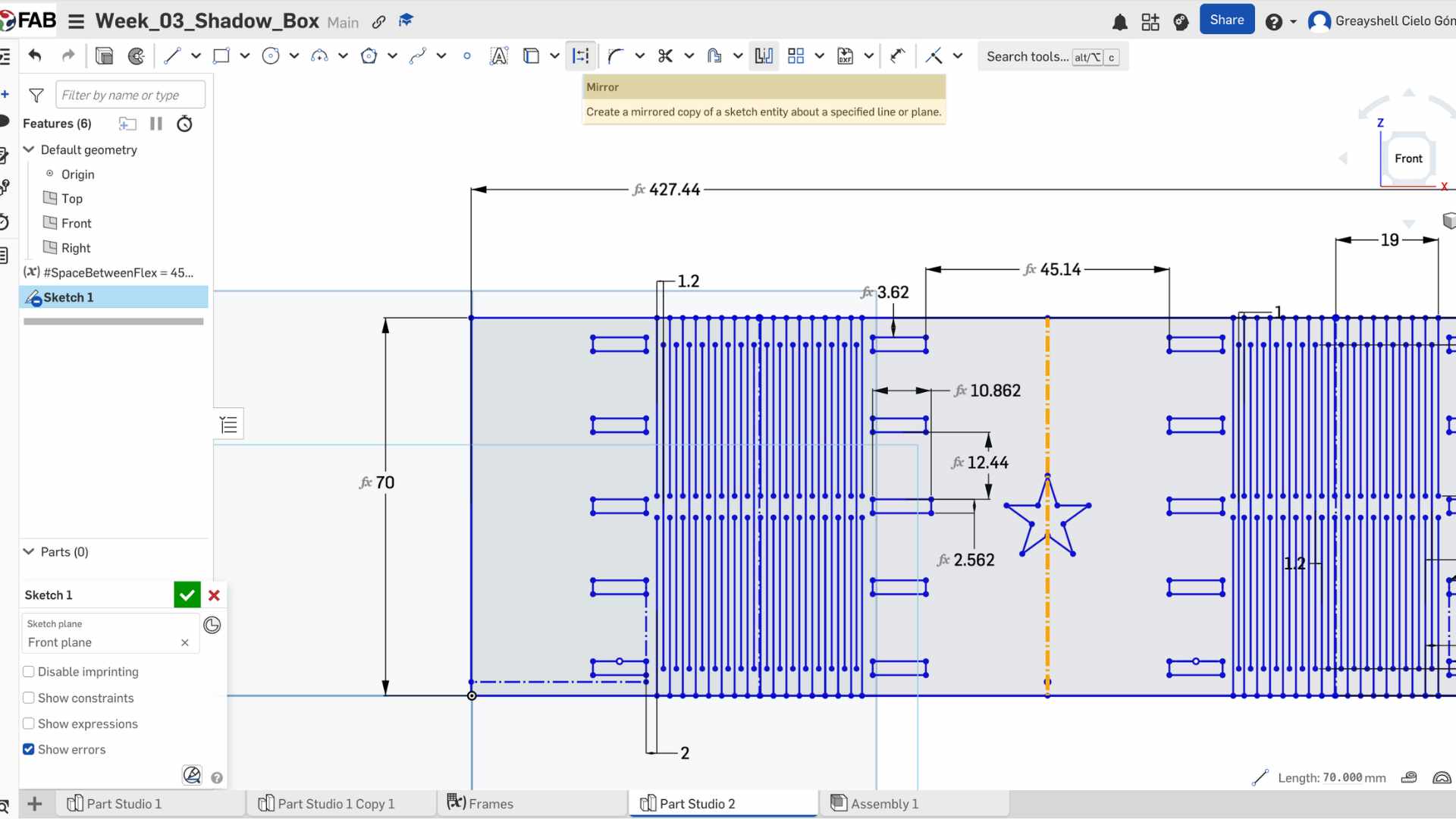
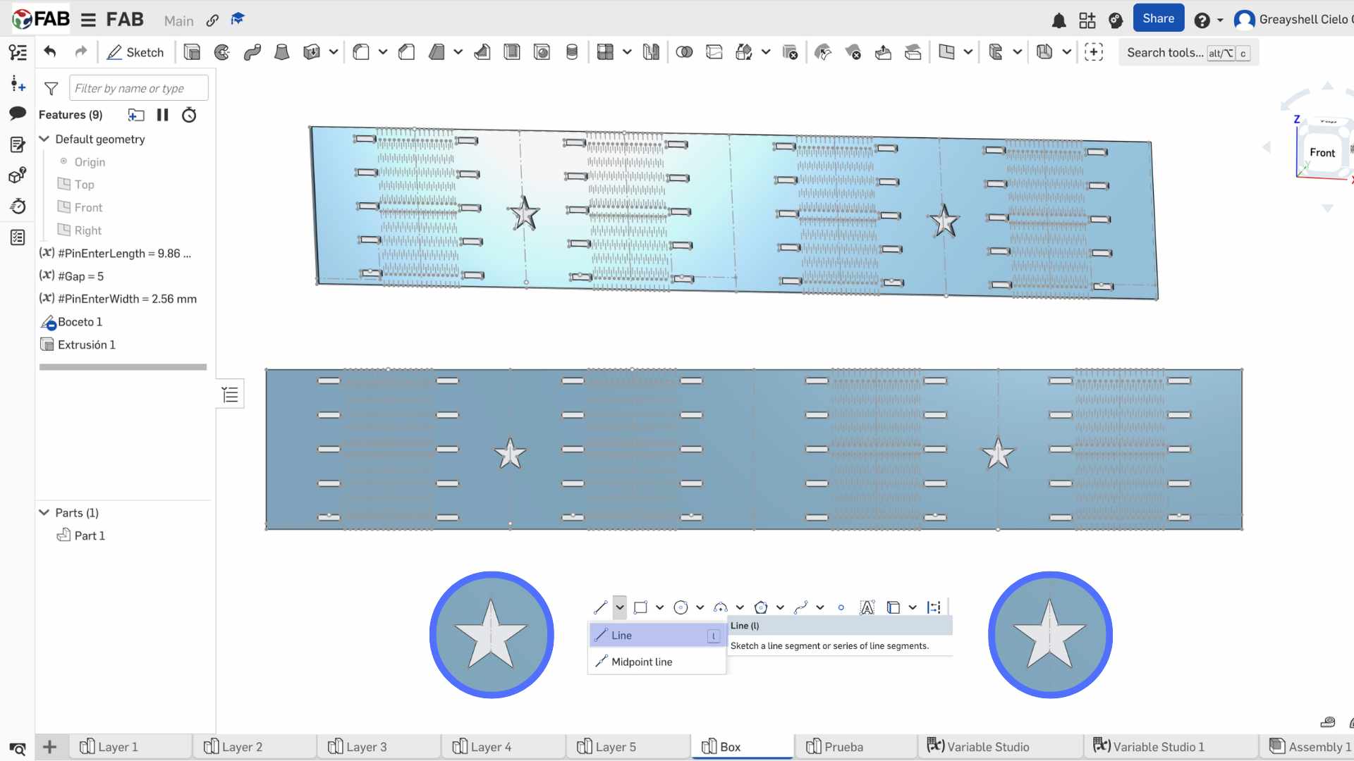
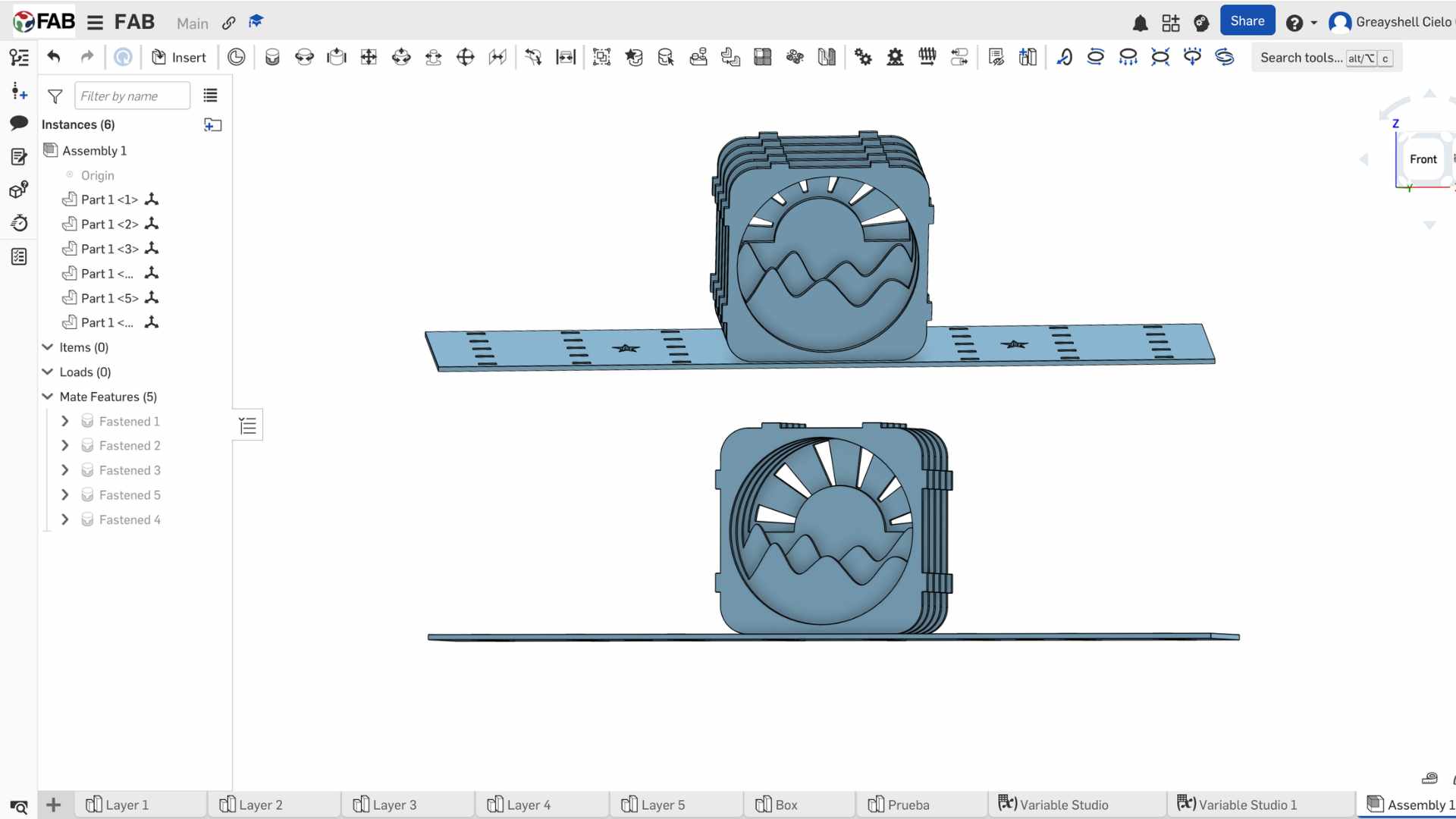
For the Computer Controlled Cutting week, I designed a modular Shadow Box. This project is ideal for demonstrating parametric design, as it requires multiple layers to fit perfectly within an external structure, accounting for both material thickness and the laser's kerf (material loss).

Design Files

In this section, you can find all the downloadable source files for the modular Shadow Box project.

DXF

01. Layer 1

Download File
CSV

02. Layer 2

Download File
SVG

03. Layer 3

Download File
PDF

04. Assembly Guide

Download File
DXF

05. Kerf Test File

Download File
ZIP

06. Box

Download File

Laser Cutting Process

My Assembly Process

Vinyl Cutting: Marine Stickers

As part of the Computer-Controlled Cutting week, I explored the use of the vinyl cutter to create decorative elements. I decided to make a set of marine-themed stickers, using adhesive vinyl to achieve a professional and durable finish.

IMAGE VECTORIZATION IN AFFINITY

For this process, I selected a marine life silhouette image from the internet. Since the vinyl cutter requires vector paths to follow, I performed a vectorization of the image. I used a specialized tool to trace the bitmap and then exported the final result in JPG format to be processed by the machine's software, ensuring the lines were clean and ready for cutting.

FINAL RESULTS

Success! The marine stickers are ready to decorate. The precision of the Roland GS-24 is excellent for these small details.

Vinyl Design Files

Download the vector files used for the marine stickers.

AF

Affinity

Original vector design with all stickers.

Download AF
JPG

Marine Stickers

File for vynil cutting.

Download JPG

Vinyl Cutting Process Video

How was it?

This week was an intensive dive into the world of Computer-Controlled Cutting, and what I enjoyed the most was the transition from a 2D digital design to a physical, functional object. Seeing the Shadow Box pieces fit together perfectly after the laser cutting process was incredibly satisfying; it validated the hours spent on parametric design and showed me the true potential of these tools for rapid prototyping.

A key learning point throughout this process was understanding the concept of Kerf and why it is so critical in digital fabrication. I discovered that you cannot simply design with nominal measurements; instead, you must account for the material lost during the cut. By calculating this value through a kerf test, I was able to adjust my design to achieve a perfect press-fit connection.