This week focused on networking and communication between devices by designing and connecting wired or wireless nodes with local input and output components using a Seeed XIAO ESP32-C6. Also, the assignment explored how different boards can exchange data, respond to signals and interact through communication protocols. For this week I will be consulting our
For this week I will be consulting our Group Assignment.
✦ What is Networking?
Networking in embedded systems refers to the communication established between two or more electronic devices (nodes)
to exchange information. These devices communicate through protocols that define how data is transmitted, received
and interpreted. Communication can be wired or wireless depending on the application, speed, distance and number of connected devices.
✦ Common Communication Protocols
These are the most common communication protocols used in embedded systems and IoT devices. Each protocol has specific characteristics that make it suitable for different applications.
Wired
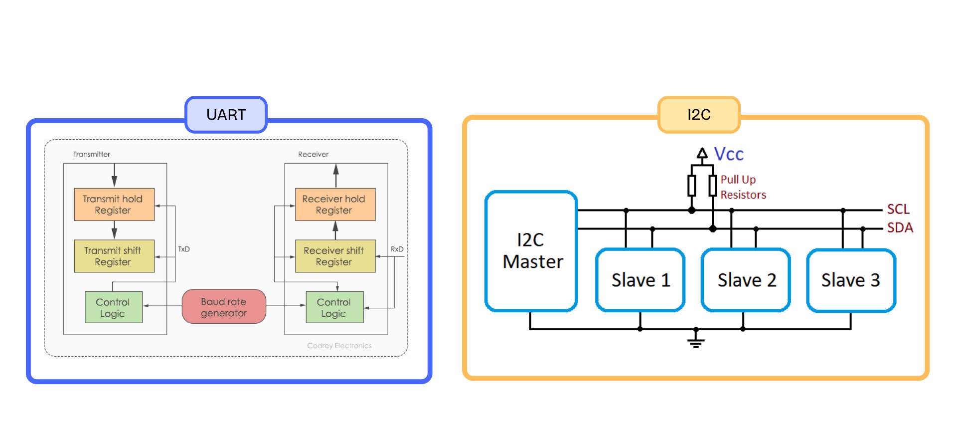
UART
Universal Asynchronous Receiver-Transmitter
TXRX
A simple serial communication protocol that uses TX (transmit) and RX (receive) lines to exchange data between two devices. Commonly used for direct communication between microcontrollers.
Wired
I2C
Inter-Integrated Circuit
SDASCL
A communication bus that allows multiple devices using only two wires. Devices operate as masters or slaves. Commonly used for sensors and board-to-board communication.
Wired
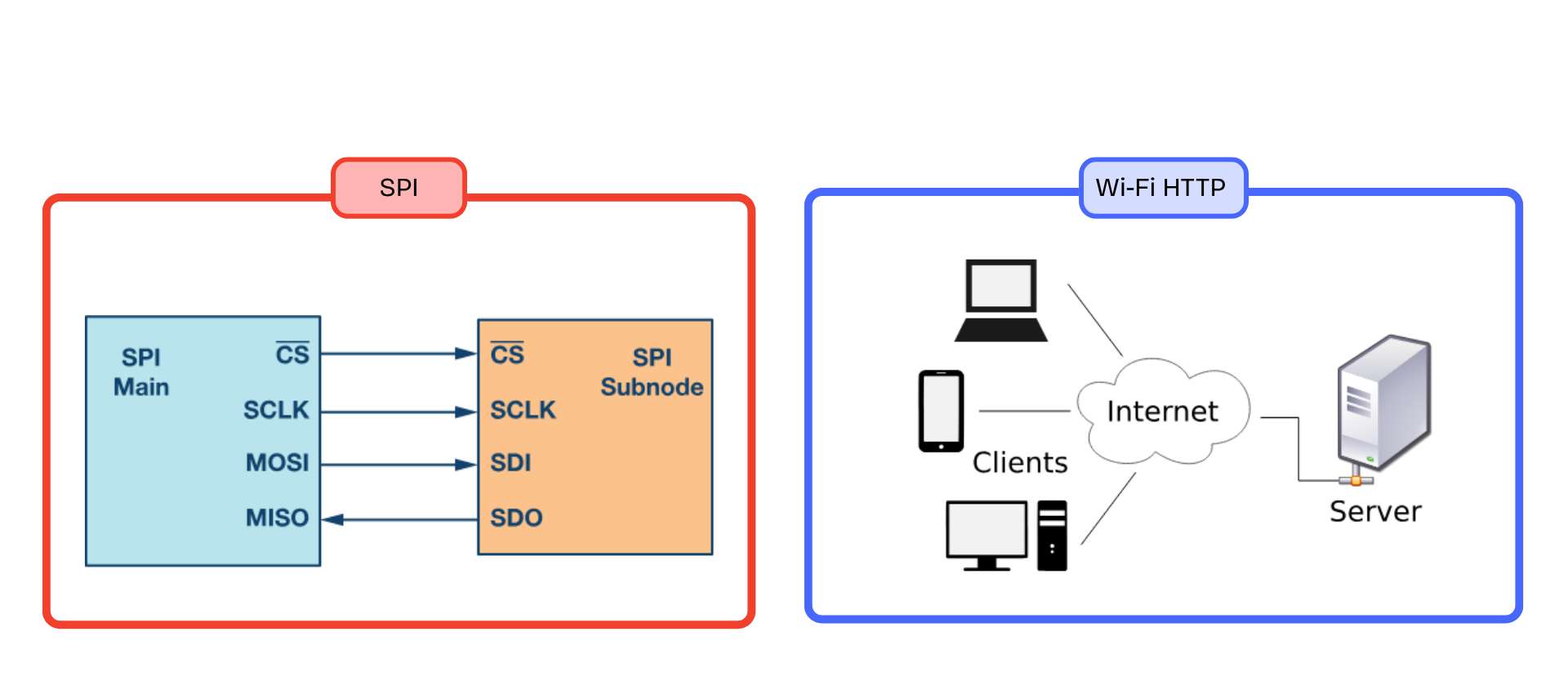
SPI
Serial Peripheral Interface
MOSIMISOSCKCS
A fast communication protocol that uses separate lines for data and clock signals. Commonly used for sensors, displays, and memory modules.
Wireless
Wi-Fi HTTP
Hypertext Transfer Protocol
GETPOST
A wireless communication method where devices exchange information through HTTP requests over a Wi-Fi network. Commonly used for web servers and IoT interfaces.
Wireless
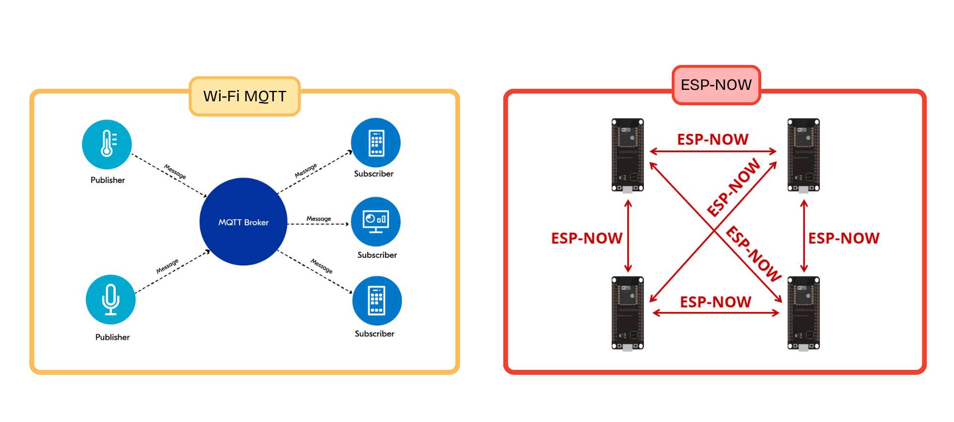
Wi-Fi MQTT
Message Queuing Telemetry Transport
PublishSubscribe
A lightweight messaging protocol designed for IoT communication. Devices publish and subscribe to data through a broker, making communication efficient and scalable.
Wireless
ESP-NOW
Espressif Direct Communication
P2PNo Router
A wireless protocol developed by Espressif that allows ESP devices to communicate directly with each other without requiring Wi-Fi internet access.
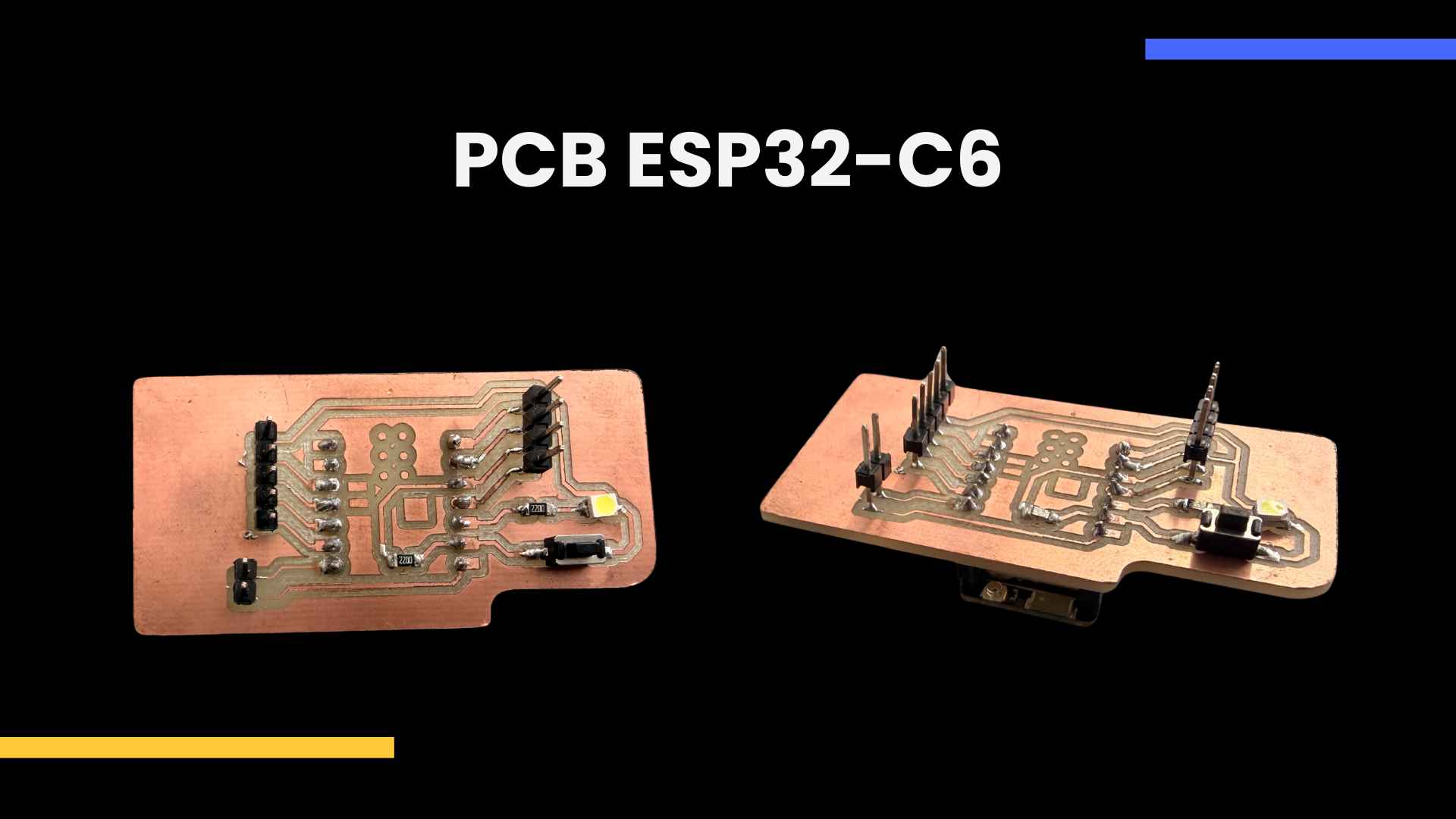
✦ XIAO ESP32-C6 PCB Design
I designed a custom PCB based on the Seeed XIAO ESP32-C6, integrating I2C & UART communication, input/output components and connection pins for networking applications.
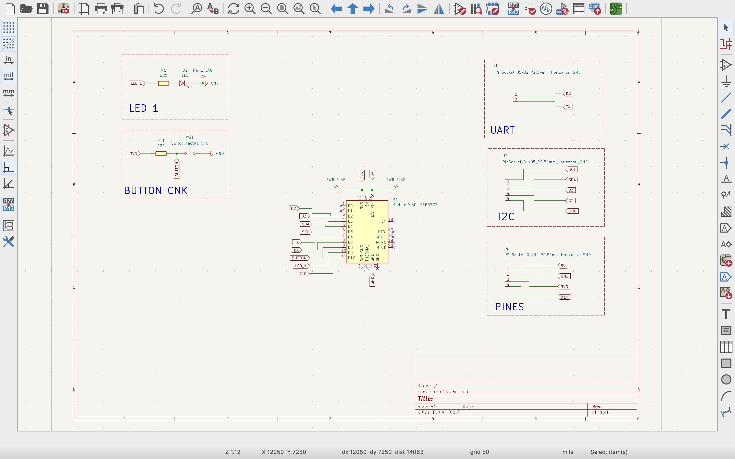
01. SCHEMATIC DESIGN
I designed the schematic in KiCad using the Seeed XIAO ESP32-C6 as the main microcontroller, integrating UART and I2C communication, a push button, an LED and additional communication pins.
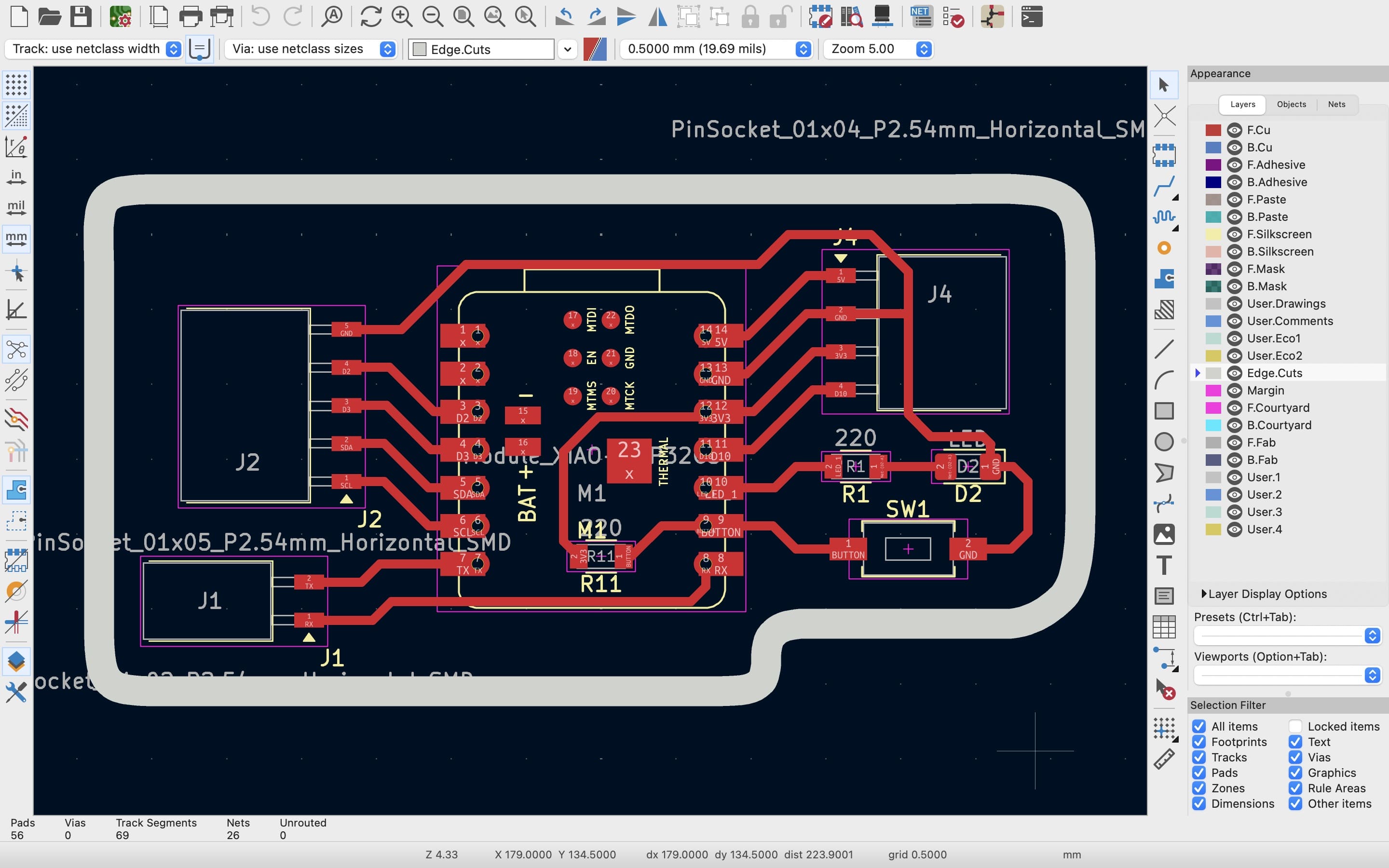
02. PCB ROUTING
After defining the schematic connections, I organized and routed the traces to create a compact PCB layout adapted to the required communication interfaces and components.
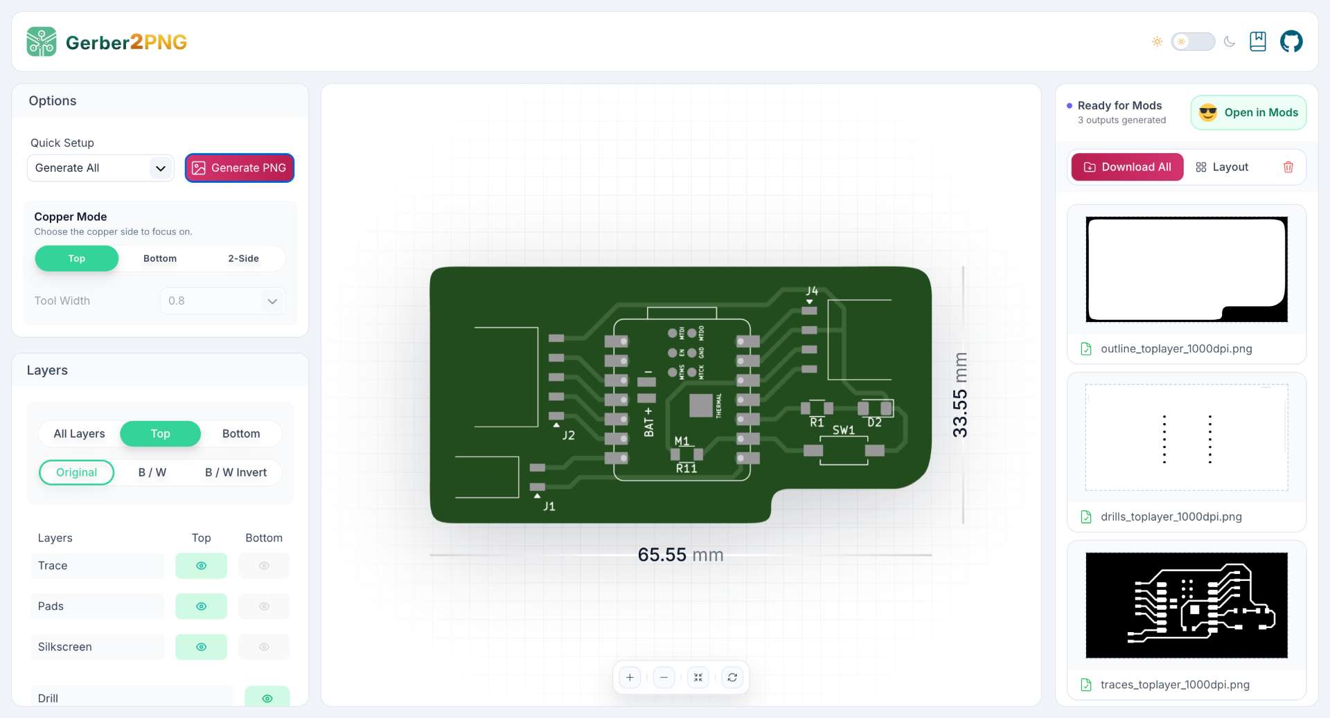
0.3 GERBER & PNG EXPORT
Once the PCB design was completed, I exported the files of Kicad and converted them into PNG images using Gerber2PNG for the milling process.
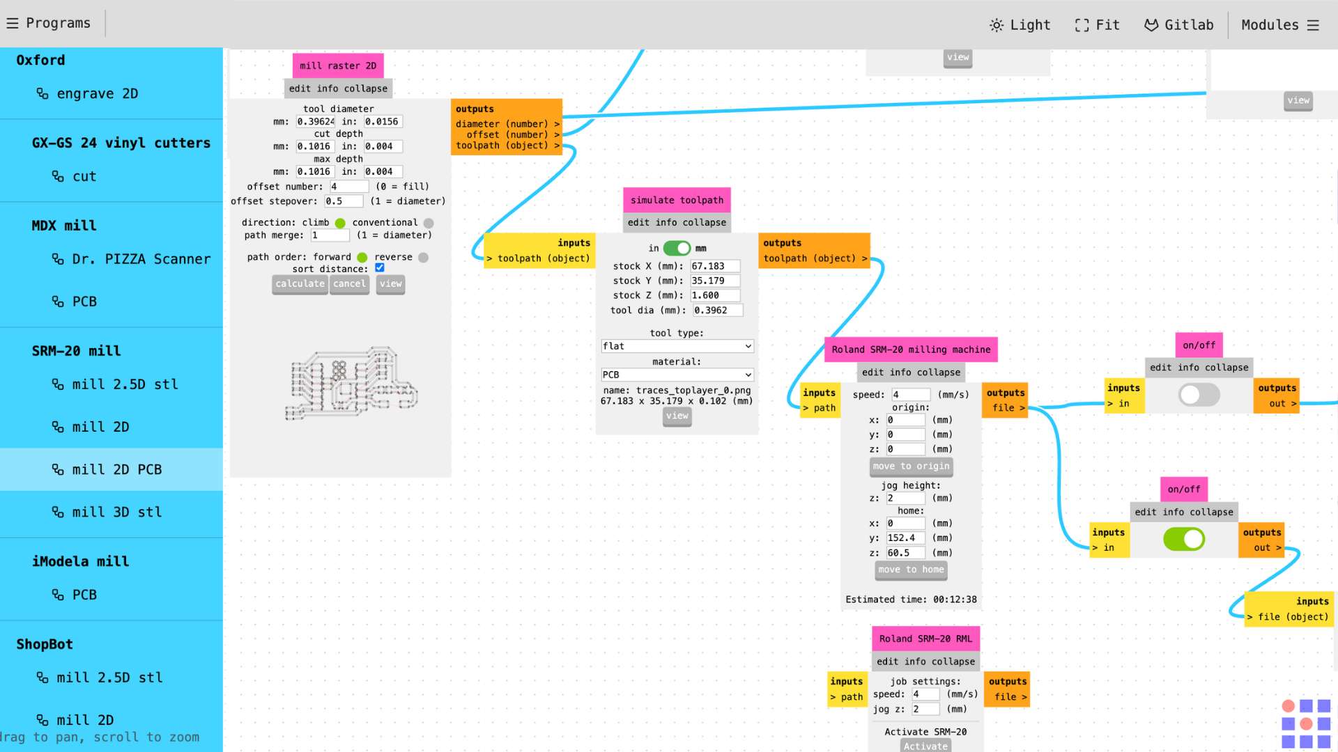
04. TOOLPATH GENERATION
I imported the PNG files into modsproject.org to generate the toolpaths for the Roland SRM-20, configuring the milling parameters for traces, drills and board outline.
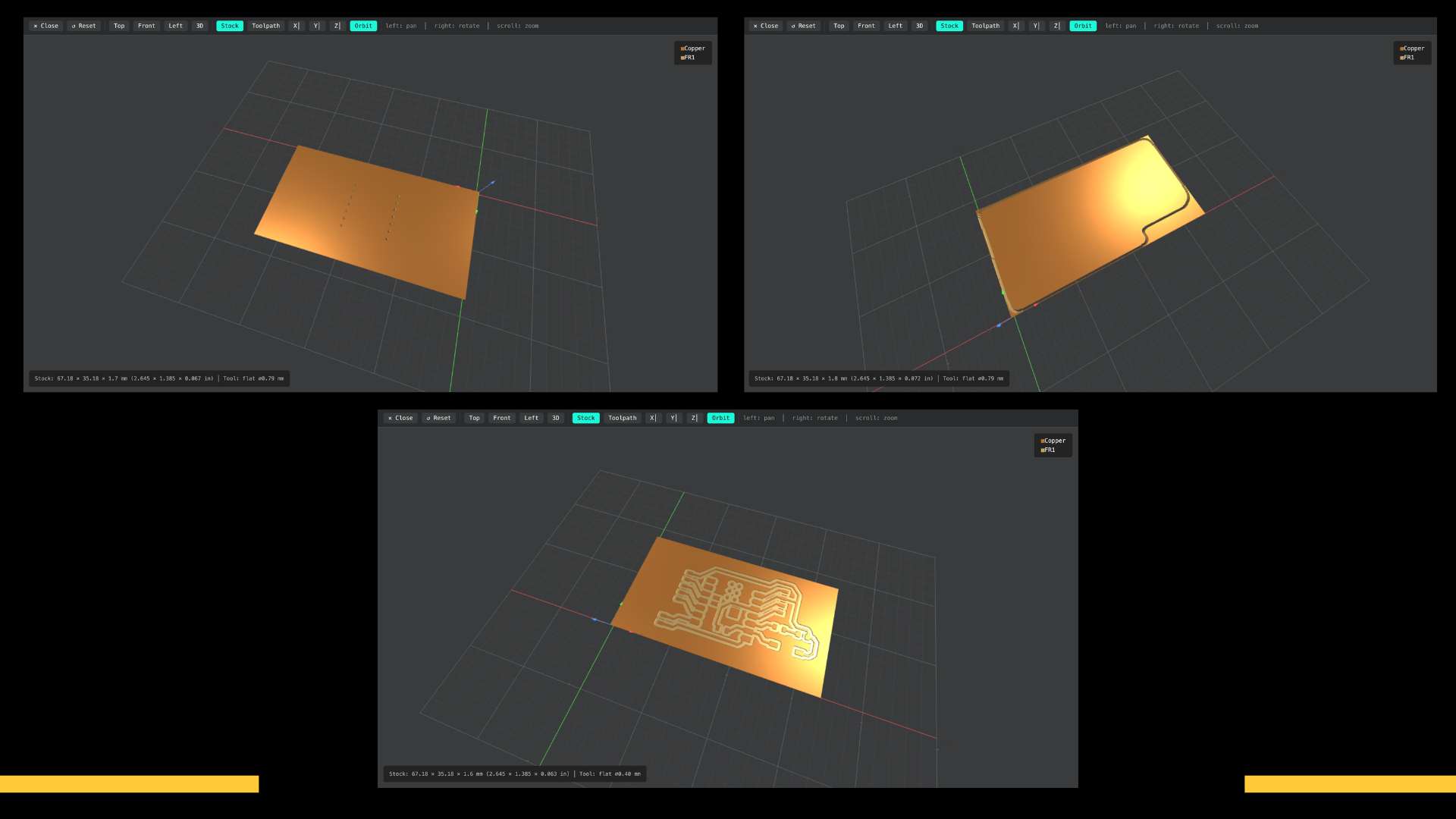
05. MILLING SIMULATION
Here is the simulation of the milling process for traces, outline and drills.
06. PCB MILLING PROCESS
I milled the PCB on the Roland SRM-20 using the generated toolpaths to engrave the traces, drill the holes and cut the final board shape.
07. COMPONENT SOLDERING
I soldered the components using flux and solder wire with the soldering iron set to approximately 270°C to achieve clean and stable connections.
08. FINAL PCB
Finally, I obtained the finished PCB with all the components assembled and ready for programming.
✦ Note:For a more detailed explanation of the PCB fabrication please go to my Week 8 documentation.
◆ Components for my PCB
◆Seeed XIAO ESP32-C6
◆2 Resistors (220Ω)
◆1 Button (CNK)
◆1 LED SMD
◆11 Male Header Pins
◆14 Female Header Pins
✦ Arduino IDE
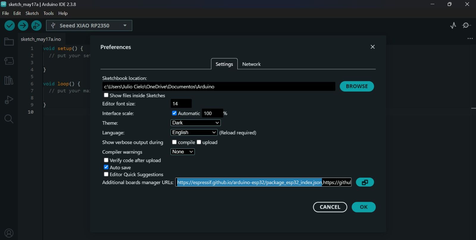
01. ARDUINO IDE PREFERENCES
I first added the ESP32 board manager URL inside the Arduino IDE preferences to enable support for the XIAO ESP32-C6 board. Arduino IDE → Settings → Additional boards manager URLs → Paste the URL: https://raw.githubusercontent.com/espressif/arduino-esp32/gh-pages/package_esp32_index.json → OK.
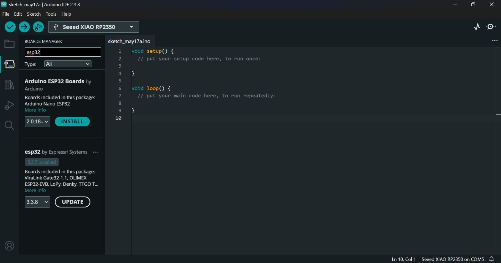
02. INSTALLING ESP32 BOARD SUPPORT
After configuring the additional URL, I searched for “ESP32” inside the Boards Manager and installed the ESP32 package by Espressif Systems.
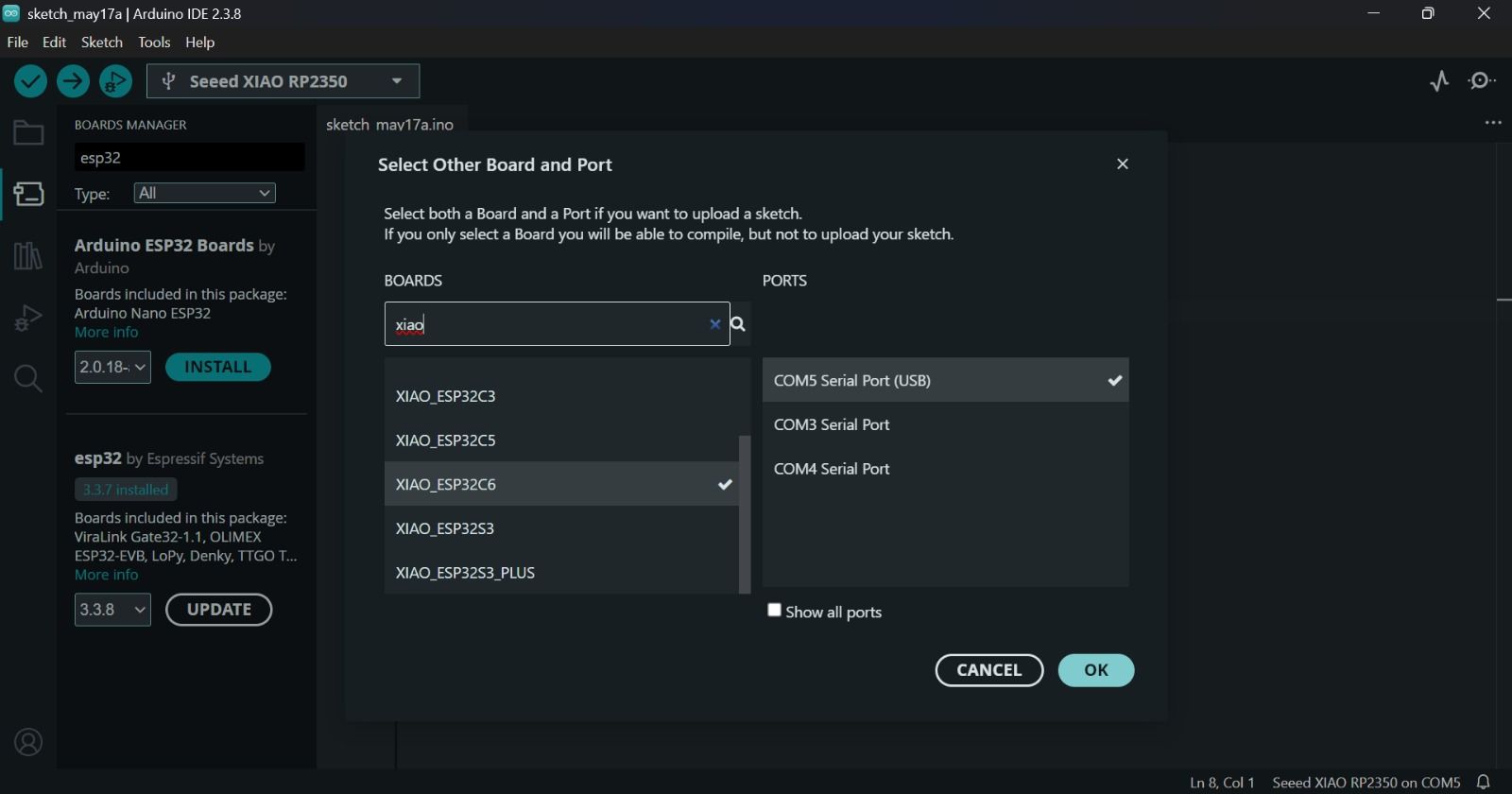
03. BOARD & PORT SELECTION
Once the installation was completed, I selected the XIAO ESP32-C6 board and the corresponding serial COM port from the board manager menu. Go to Tools → Board → Select Seeed XIAO ESP32C6
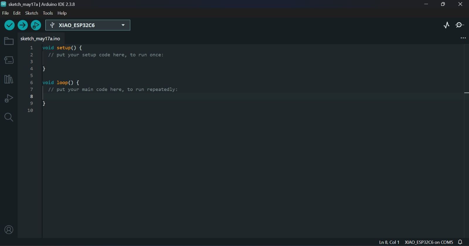
04. ESP32-C6 READY FOR PROGRAMMING
After completing the setup process, the Arduino IDE successfully recognized the XIAO ESP32-C6 board, allowing the programming and UART communication tests to begin.
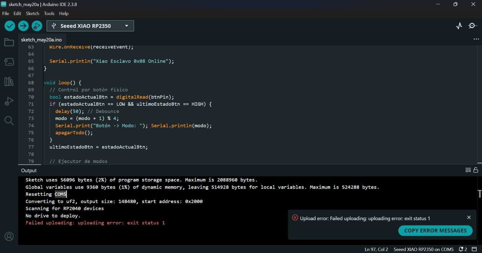
Initially, I attempted to implement I2C communication between the Seeed XIAO ESP32-C6 and the RP2350.
However, due to a known RP2350 slave-mode bug in Arduino IDE, the communication became unstable. As a solution,
I switched to UART communication, which provided a simpler and more reliable serial connection between both
microcontrollers.
✦ UART Communication
UART communication was implemented between the Seeed XIAO ESP32-C6 and the RP2350 using TX and RX serial lines.
Both boards acted as communication nodes capable of sending and receiving data through serial transmission,
allowing a stable wired connection between different microcontroller architectures. Each board acted as an independent node and communication roles were defined as transmitter and receiver.
◆ Components I'll be using
◆1 Seeed XIAO ESP32-C6 Board
◆1 Seeed XIAO RP2350 Board
◆1 Servomotor SG90>
◆1 NeoPixel Ring (WS2812B)
◆6 male-to-female Dupont cables
✦ ESP32-C6 Code Development (C++)
#include < ESP32Servo.h > // Servo control library
// ── Servo ─────────────────────────────────
#define SERVO_PIN D10 // Servo connected to pin D10
Servo myServo;
// ── UART Communication with RP2350 ───────
HardwareSerial rpSerial(1); // Create UART communication port
#define RP_RX 17 // ESP32-C6 RX pin
#define RP_TX 16 // ESP32-C6 TX pin
int currentMode = 1;
void setup() {
Serial.begin(115200);
// Starts serial monitor communication
rpSerial.begin(9600, SERIAL_8N1, RP_RX, RP_TX);
// Initializes UART communication at 9600 baud rate
delay(2000);
myServo.attach(SERVO_PIN);
// Attaches the servo to the selected pin
myServo.write(90);
// Moves servo to center position
Serial.println("ESP32-C6 ready");
}
void sendCommand(String cmd) {
rpSerial.println(cmd);
// Sends command to the RP2350 board
Serial.println("Sent: " + cmd);
unsigned long t = millis();
while (millis() - t < 800) {
// Waits for a response during 800 ms
if (rpSerial.available()) {
String r = rpSerial.readStringUntil('\n');
// Reads incoming UART message
r.trim();
Serial.println("RP2350 response: " + r);
break;
}
}
}
void loop() {
sendCommand("CMD:MODE:1");
myServo.write(90);
// Servo centered
Serial.println("Servo: center");
delay(3000);
sendCommand("CMD:MODE:2");
myServo.write(0);
// Servo moves left
Serial.println("Servo: left");
delay(3000);
sendCommand("CMD:MODE:3");
myServo.write(180);
// Servo moves right
Serial.println("Servo: right");
delay(3000);
sendCommand("CMD:MODE:4");
myServo.write(90);
// Servo returns to center
Serial.println("Servo: center");
delay(3000);
}
✦ Note:The following libraries need to be installed for the code: Adafruit NeoPixel
Command
Description
Serial.begin()
Starts serial communication.
rpSerial.begin()
Initializes UART communication between boards.
Servo.attach()
Connects the servo to a selected pin.
Servo.write()
Moves the servo to a specific angle.
Serial.println()
Prints messages to the serial monitor.
rpSerial.println()
Sends UART messages to the RP2350.
rpSerial.available()
Checks if incoming data is available.
readStringUntil()
Reads incoming serial data until a character is found.
delay()
Pauses the program for a specified time.
✦ RP2350 Code Development (C++)
#include < Adafruit_NeoPixel.h >
// Library for controlling NeoPixel LEDs
// ── NeoPixel Ring ─────────────────────────
#define NEO_PIN 26
// NeoPixel data pin
#define NEO_COUNT 16
// Number of LEDs in the ring
Adafruit_NeoPixel ring(NEO_COUNT, NEO_PIN, NEO_GRB + NEO_KHZ800);
// ── Variables ─────────────────────────────
int currentMode = 1;
int currentBrightness = 200;
void setup() {
Serial.begin(115200);
// Starts USB serial communication for debugging
Serial1.begin(9600);
// Starts UART communication with the ESP32-C6
delay(1000);
ring.begin();
// Initializes the NeoPixel ring
ring.setBrightness(currentBrightness);
// Sets LED brightness
ring.show();
Serial.println("RP2350 ready");
applyMode();
}
// ── Lighting Modes ───────────────────────
void warmMode() {
for (int i = 0; i < NEO_COUNT; i++)
ring.setPixelColor(i, ring.Color(255, 120, 20));
// Warm orange color
ring.show();
}
void coolMode() {
for (int i = 0; i < NEO_COUNT; i++)
ring.setPixelColor(i, ring.Color(100, 180, 255));
// Cool blue color
ring.show();
}
void rainbowMode() {
for (int i = 0; i < NEO_COUNT; i++) {
int hue = (i * 65536L / NEO_COUNT);
ring.setPixelColor(i, ring.gamma32(ring.ColorHSV(hue)));
// Rainbow effect
}
ring.show();
}
void offMode() {
ring.clear();
// Turns off all LEDs
ring.show();
}
// ── Applies Current Mode ─────────────────
void applyMode() {
if (currentMode == 1) warmMode();
else if (currentMode == 2) coolMode();
else if (currentMode == 3) rainbowMode();
else if (currentMode == 4) offMode();
}
// ── Processes Incoming Commands ──────────
void processCommand(String cmd) {
cmd.trim();
Serial.println("Received: " + cmd);
if (cmd.startsWith("CMD:MODE:")) {
currentMode = cmd.substring(9).toInt();
// Extracts the mode number
applyMode();
Serial1.println("ACK:OK");
// Sends confirmation back to ESP32-C6
} else if (cmd.startsWith("CMD:BRIGHT:")) {
currentBrightness = cmd.substring(11).toInt();
// Extracts brightness value
ring.setBrightness(currentBrightness);
applyMode();
Serial1.println("ACK:OK");
} else {
Serial1.println("ERR:UNKNOWN");
// Sends error if command is invalid
}
}
// ── Main Loop ────────────────────────────
void loop() {
if (Serial1.available()) {
// Checks if UART data is available
String cmd = Serial1.readStringUntil('\n');
// Reads incoming command
processCommand(cmd);
}
}
✦ Note:The following libraries need to be installed for the code: ESP32Servo
Command
Description
Serial.begin()
Starts USB serial communication for debugging.
Serial1.begin()
Initializes UART communication with the ESP32
ring.begin()
Initializes the NeoPixel ring.
ring.setBrightness()
Adjusts the LED brightness level.
ring.setPixelColor()
Sets the color of individual LEDs.
ring.show()
Updates and displays the LED changes.
ColorHSV()
Generates colors using HSV values.
substring()
Extracts values from incoming UART commands.
toInt()
Converts received text into integer values.
Serial1.available()
Checks if UART data is available.
readStringUntil()
Reads incoming UART data until a character is found.
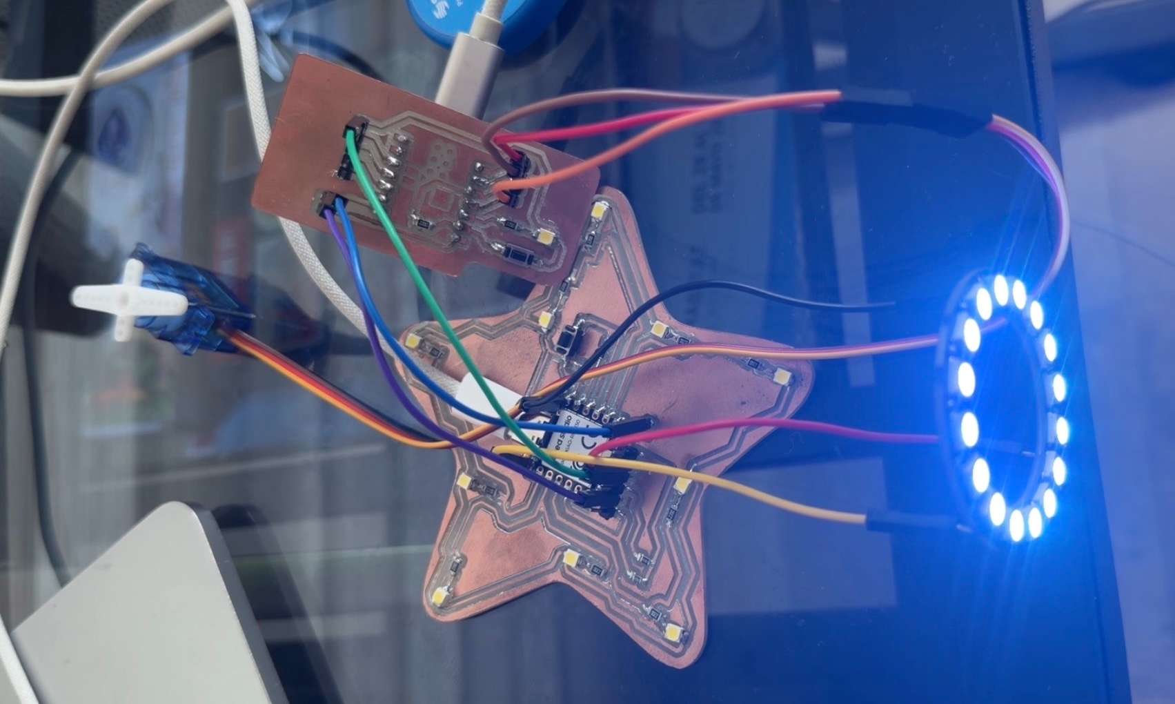
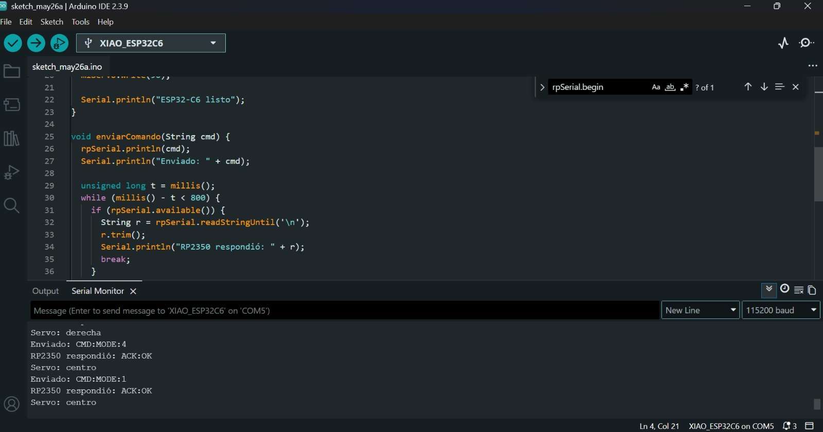
✦ Communication Test
This was the final result. The two boards were connected to different computers and with wired communication between them.
✦ Part 2: ESP-NOW + WiFi Communication
Although UART allowed successful data exchange, it's a point-to-point serial communication protocol.
The devices communicate through TX and RX wires and don't form a network. That's why I decided to use the ESP-NOW protocol
communication approach that better demonstrated networking concepts.
This consisted of a wireless communication system using two ESP32-C6 boards and ESP-NOW. A web interface hosted on
the sender board allowed a smartphone to send commands, which were received by a second ESP32-C6 (my friend Majo lent me her MCU for the exercise), and used to control a NeoPixel
ring.
System Architecture
✦ System Architecture
The system consisted of three main components working together to enable wireless NeoPixel control from a smartphone browser.
Component 01
Sender ESP32-C6
The sender board acted as the main controller and user-facing interface.
Connected to WiFi
Hosted a local HTML interface
Received user commands from a smartphone
Transmitted commands wirelessly using ESP-NOW
Component 02
Receiver ESP32-C6
The receiver board handled incoming commands and drove the NeoPixel ring directly.
Received ESP-NOW messages
Interpreted the incoming commands
Controlled a 16-pixel NeoPixel ring
Component 03
User Interface
A minimal web interface served directly from the sender board, accessible from any device on the same network.
Accessed from a smartphone browser
Sent commands through the sender board
Allowed wireless control of the NeoPixel animations
✦ ESP32-C6 Sender Code (C++)
#include <WiFi.h>
#include <WebServer.h>
#include <esp_now.h>
// Receiver ESP32-C6 MAC address
uint8_t receiverAddress[] = {0x58, 0xE6, 0xC5, 0x11, 0x1B, 0x14};
// WiFi credentials
const char* WIFI_SSID = "iPhoneGreay";
const char* WIFI_PASSWORD = "greayshell";
WebServer server(80);
// Data structure sent through ESP-NOW
typedef struct struct_message {
int mode;
int brightness;
} struct_message;
struct_message dataToSend;
int currentMode = 1;
int currentBrightness = 200;
// Send data to the receiver board
void sendCommand(int mode, int brightness) {
dataToSend.mode = mode;
dataToSend.brightness = brightness;
esp_now_send(receiverAddress,
(uint8_t*)&dataToSend,
sizeof(dataToSend));
Serial.print("Sent mode: ");
Serial.println(mode);
}
// Generate the HTML control page
void handleRoot() {
String html = "";
html += "<!DOCTYPE html><html><head>";
html += "<meta charset='utf-8'>";
html += "<meta name='viewport' content='width=device-width, initial-scale=1'>";
html += "<title>Smart Lamp</title>";
html += "<style>";
html += "body{font-family:sans-serif;text-align:center;background:#111;color:white;padding:20px;}";
html += "h1{color:#FFB347;}";
html += ".btn{display:inline-block;margin:10px;padding:20px 30px;border:none;border-radius:12px;font-size:18px;cursor:pointer;width:140px;}";
html += ".warm{background:#FF6B00;color:white;}";
html += ".cool{background:#4A90D9;color:white;}";
html += ".rainbow{background:#9B59B6;color:white;}";
html += ".off{background:#333;color:white;}";
html += "input[type=range]{width:80%;margin:20px 0;}";
html += "</style></head><body>";
html += "<h1>Smart Lamp</h1>";
html += "<p>";
html += "<button class='btn warm' onclick=\"fetch('/mode?m=1')\">Warm</button>";
html += "<button class='btn cool' onclick=\"fetch('/mode?m=2')\">Cool</button>";
html += "</p>";
html += "<p>";
html += "<button class='btn rainbow' onclick=\"fetch('/mode?m=3')\">Rainbow</button>";
html += "<button class='btn off' onclick=\"fetch('/mode?m=4')\">Off</button>";
html += "</p>";
html += "<p>Brightness</p>";
html += "<input type='range' min='50' max='255' value='200' ";
html += "oninput=\"fetch('/brightness?b='+this.value)\">";
html += "</body></html>";
server.send(200, "text/html", html);
}
// Change lighting mode
void handleMode() {
if (server.hasArg("m")) {
currentMode = server.arg("m").toInt();
sendCommand(currentMode, currentBrightness);
}
server.send(200, "text/plain", "OK");
}
// Change brightness level
void handleBrightness() {
if (server.hasArg("b")) {
currentBrightness = server.arg("b").toInt();
sendCommand(currentMode, currentBrightness);
}
server.send(200, "text/plain", "OK");
}
void setup() {
// Start serial monitor
Serial.begin(115200);
delay(1000);
// Connect to WiFi
WiFi.mode(WIFI_AP_STA);
WiFi.begin(WIFI_SSID, WIFI_PASSWORD);
Serial.print("Connecting to WiFi");
while (WiFi.status() != WL_CONNECTED) {
delay(500);
Serial.print(".");
}
Serial.println();
Serial.print("IP Address: ");
Serial.println(WiFi.localIP());
// Initialize ESP-NOW
if (esp_now_init() != ESP_OK) {
Serial.println("ESP-NOW init failed");
return;
}
// Register receiver board
esp_now_peer_info_t peerInfo = {};
memcpy(peerInfo.peer_addr, receiverAddress, 6);
peerInfo.channel = WiFi.channel();
peerInfo.encrypt = false;
esp_now_add_peer(&peerInfo);
// Web server routes
server.on("/", handleRoot);
server.on("/mode", handleMode);
server.on("/brightness", handleBrightness);
server.begin();
Serial.println("Sender ready");
// Default state
sendCommand(1, 200);
}
void loop() {
// Handle requests from the phone
server.handleClient();
}
Command
Description
Serial.begin()
Starts USB serial communication for debugging.
WiFi.begin()
Connects the ESP32-C6 to the WiFi network.
esp_now_init()
Initializes ESP-NOW communication.
esp_now_add_peer()
Registers the receiver board as a communication peer.
esp_now_send()
Sends data wirelessly to the receiver ESP32-C6.
server.on()
Creates web routes for user interactions.
fetch()
Sends commands from the web interface without reloading the page.
server.begin()
Starts the web server.
server.handleClient()
Processes incoming web requests.
sendCommand()
Custom function that sends data through ESP-NOW.
✦ ESP32-C6 Receiver (C++)
#include <WiFi.h>
#include <esp_now.h>
#include <Adafruit_NeoPixel.h>

// NeoPixel setup
#define NEO_PIN    D0
#define NEO_COUNT  16
Adafruit_NeoPixel ring(NEO_COUNT, NEO_PIN, NEO_GRB + NEO_KHZ800);

// WiFi credentials
const char* WIFI_SSID     = "iPhoneGreay";
const char* WIFI_PASSWORD = "greayshell";

// Variables for light effects
int currentMode = 1;
int currentBrightness = 200;
float breath = 0;
float rainbowAngle = 0;
unsigned long lastFrame = 0;

// Data received from sender
typedef struct struct_message {
  int mode;
  int brightness;
} struct_message;

struct_message receivedData;

// Warm orange breathing effect
void effectOrange() {
  breath += 0.03;
  if (breath > 2 * PI) breath = 0;

  float b = (sin(breath) + 1.0) / 2.0;

  for (int i = 0; i < NEO_COUNT; i++)
    ring.setPixelColor(i, ring.Color((uint8_t)(b*255), (uint8_t)(b*80), 0));

  ring.show();
}

// Blue and purple wave effect
void effectWave() {
  breath += 0.05;
  if (breath > 2 * PI) breath = 0;

  for (int i = 0; i < NEO_COUNT; i++) {
    float phase = breath + (i * (2 * PI / NEO_COUNT));
    float b = (sin(phase) + 1.0) / 2.0;

    ring.setPixelColor(i, ring.Color((uint8_t)(b*80), (uint8_t)(b*20), (uint8_t)(b*255)));
  }

  ring.show();
}

// Rotating rainbow effect
void effectRainbow() {
  rainbowAngle += 300;
  if (rainbowAngle > 65536) rainbowAngle = 0;

  breath += 0.04;
  if (breath > 2 * PI) breath = 0;

  float pulse = (sin(breath) + 1.0) / 2.0;
  ring.setBrightness((int)(100 + pulse * 155));

  for (int i = 0; i < NEO_COUNT; i++) {
    int hue = ((int)rainbowAngle + (i * 65536L / NEO_COUNT)) % 65536;
    ring.setPixelColor(i, ring.gamma32(ring.ColorHSV(hue)));
  }

  ring.show();
}

// Turn off all LEDs
void effectOff() {
  ring.clear();
  ring.show();
}

// Runs when ESP-NOW data is received
void onDataReceived(const esp_now_recv_info_t* info, const uint8_t* data, int dataLen) {
  memcpy(&receivedData, data, sizeof(receivedData));

  currentMode = receivedData.mode;
  currentBrightness = receivedData.brightness;

  breath = 0;
  rainbowAngle = 0;

  ring.setBrightness(currentBrightness);

  Serial.print("Mode received: ");
  Serial.println(currentMode);
}

void setup() {
  Serial.begin(115200);
  delay(1000);

  // Start NeoPixel ring
  ring.begin();
  ring.setBrightness(currentBrightness);
  ring.clear();
  ring.show();

  // Connect to WiFi
  WiFi.mode(WIFI_STA);
  WiFi.begin(WIFI_SSID, WIFI_PASSWORD);

  Serial.print("Connecting to WiFi");

  while (WiFi.status() != WL_CONNECTED) {
    delay(500);
    Serial.print(".");
  }

  Serial.println();
  Serial.print("Receiver IP: ");
  Serial.println(WiFi.localIP());

  // Initialize ESP-NOW
  if (esp_now_init() != ESP_OK) {
    Serial.println("ESP-NOW init failed");
    return;
  }

  // Receive data from sender
  esp_now_register_recv_cb(onDataReceived);

  Serial.println("Receiver ready");
}

void loop() {
  // Update light effect
  if (millis() - lastFrame > 20) {
    lastFrame = millis();

    if      (currentMode == 1) effectOrange();
    else if (currentMode == 2) effectWave();
    else if (currentMode == 3) effectRainbow();
    else if (currentMode == 4) effectOff();
  }
}
Command
Description
Serial.begin()
Starts USB serial communication for debugging.
ring.begin()
Initializes the NeoPixel ring.
ring.setBrightness()
Sets the brightness level of the LEDs.
ring.setPixelColor()
Adjusts the LED brightness level.
ring.setPixelColor()
Sets the color of individual LEDs.
ring.show()
Updates and displays the LED changes.
WiFi.begin()
Connects the receiver board to the WiFi network.
esp_now_init()
Initializes ESP-NOW communication.
esp_now_register_recv_cb()
Registers the function that runs when data is received.
memcpy()
Copies the received ESP-NOW data into the message structure.
effectOrange()
Creates a warm breathing light effect.
effectWave()
Creates a blue and purple wave animation.
effectOff()
Turns off all LEDs.
✦ Communication Test ESP-NOW
The wireless communication was successfully established between both ESP32-C6 boards. The receiver correctly interpreted the commands sent from the HTML interface and updated the NeoPixel ring in real time.
✦ Reflection
During this assignment, I faced several communication challenges. My first approach was using I2C, but I struggled with
unstable connections and debugging issues. After several tests, I switched to UART, which worked much more reliably. However,
since UART is limited to point-to-point communication, I later explored ESP-NOW to create a wireless communication system between two ESP32-C6 boards.
Although setting up the connection took some experimentation, it was very rewarding to see commands being sent from my phone and received by the
NeoPixel ring in real time. This process helped me better understand the differences between wired and wireless communication
and gave me more confidence working with networking concepts.
✦ Download Here!
In this section, you can find the downloadable source files developed during this week.

.jpg)