✦ Understanding 3D Prinitng
During the week focused on 3D printing and scanning, I learned about the fundamental principles behind additive manufacturing and how they are different from traditional subtractive processes. Through the Group Assignment, I explored key concepts such as structural implications, print parameters, layer height, overhang angles and how dimensional tolerances affect the final result of the 3D print.
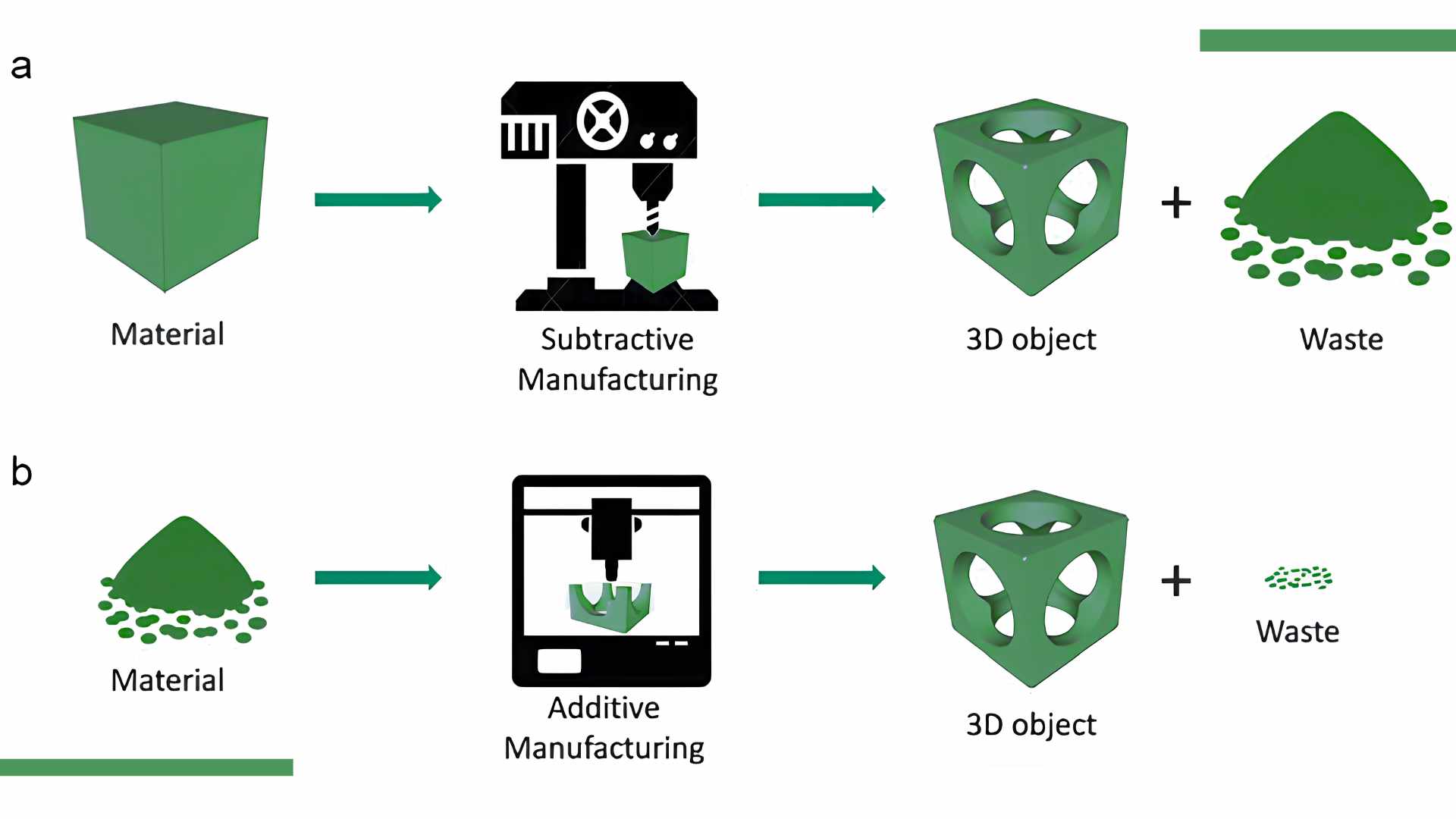
✦ Additive vs. Subtractive Manufacturing
Additive manufacturing builds objects layer by layer, allowing the creation of complex internal geometries and enclosed mechanisms that would be difficult to achieve otherwise. Meanwhile, subtractive processes such as CNC milling or laser cutting, remove material and are limited when creating enclosed features.
✦ Slicer
A slicer is the software that acts as a translator between a 3D model file (STL/OBJ) and the 3D printer. Its function is to divide the model into horizontal layers and generate G-code, which contains instructions and extrusion parameters that the printer executes.
Advantages and Disadvantages of 3D Printing
✦ Designing a Gyroscopic
For this assignment I would be doing a CAD model of a Gyroscopic, all in a print-in-place concentric ring mechanism. The design consists of multiple nested circular rings enclosed within an outer frame, allowing rotational movement without post-processing assembly.
✦ Why 3D Printing?
In print-in-place designs, it is essential to incorporate clearance between components, since without the adequate spacing, the parts would fuse together during the printing, resulting in a single solid piece with no movement. This mechanism cannot be manufactured using subtractive processes because the concentric rings are geometrically enclosed to cutting tools. Additive manufacturing enables the fabrication of trapped moving components in a single print.
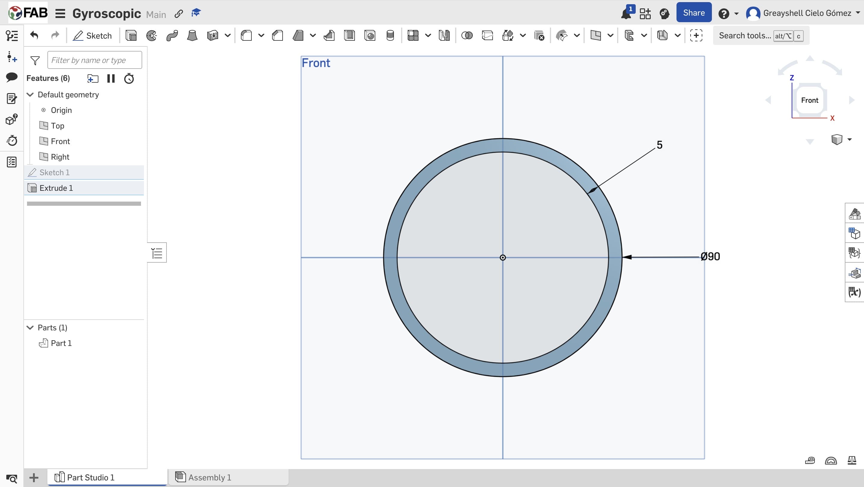
01. Outer Ring
For the modeling process I used Onshape, and I began by sketching and extruding a circle to define the outer ring. To encapsulate one ring within another, a male-female interlocking system was implemented.
02. Encapsulate Rings
Using a secondary construction plane, two internal cylindric features with a diameter of 3.0 mm (male elements) were extruded in the outer ring. These correspond to 3.6 mm cavities (female elements) modeled in the adjacent ring, resulting in a 0.3 mm radial clearance.
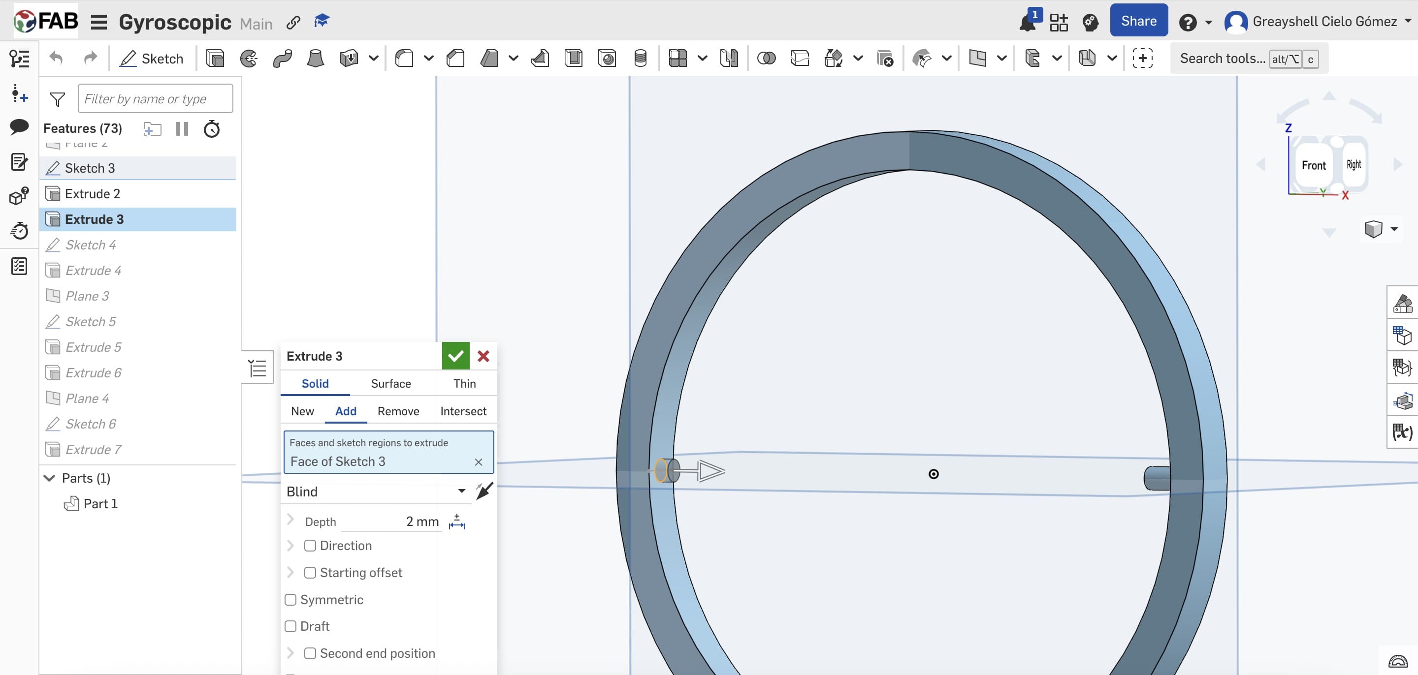
✦ This dimensional offset compensates for FDM tolerances and prevents the fusion between the concentric components, allowing smooth rational moving after printing. Besides, each ring was extruded as an independent solid body within the same Part Studio to preserve the print-in-place functionality.
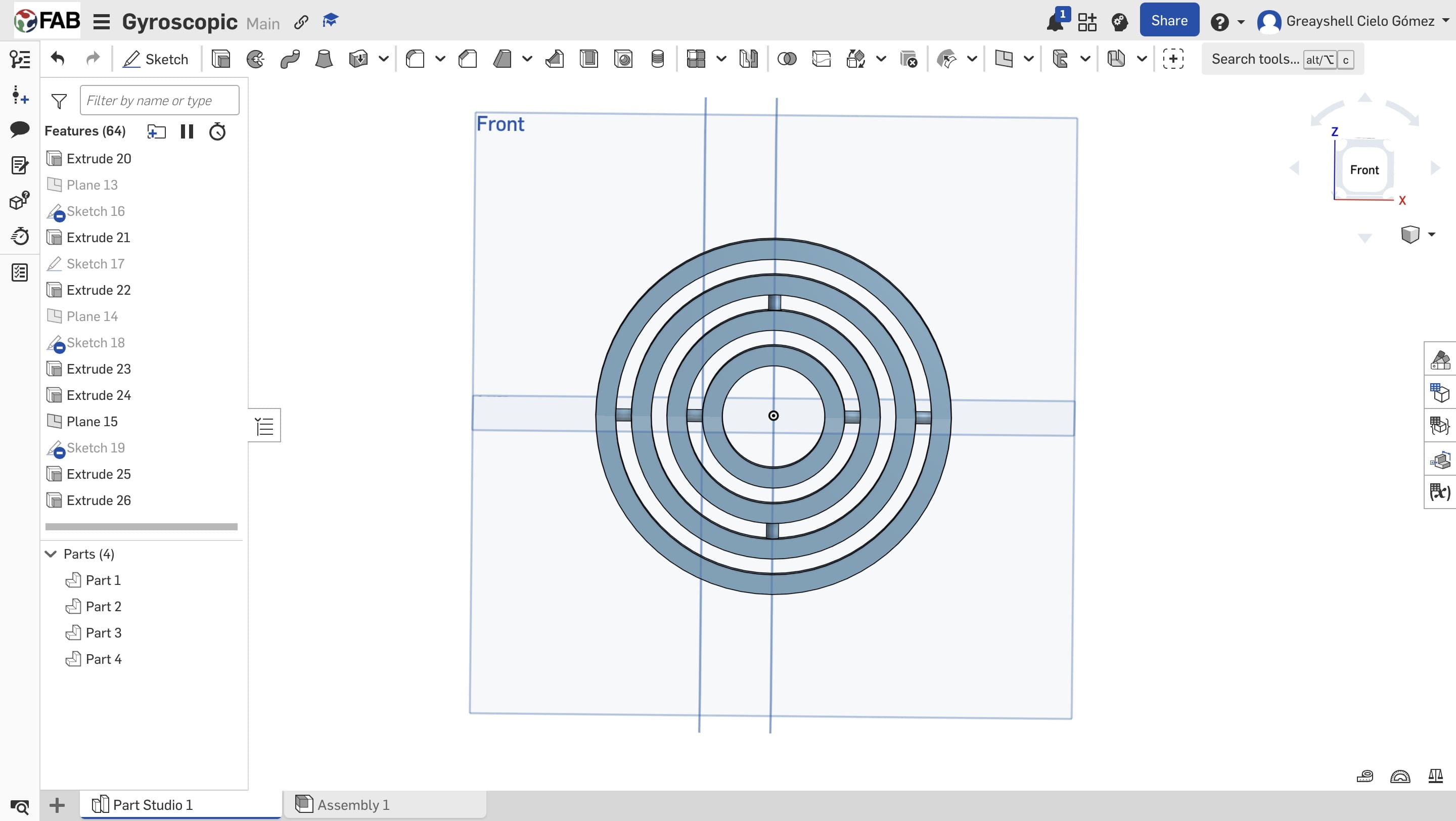
03. Position of the Cavities
The same process was repeated for subsequent rings, altering the position of the male-female features to maintain rotational and structural balance. The cavities were positioned at 0º and 180º in one ring, and at 90º and 270º in the adjacent ring.
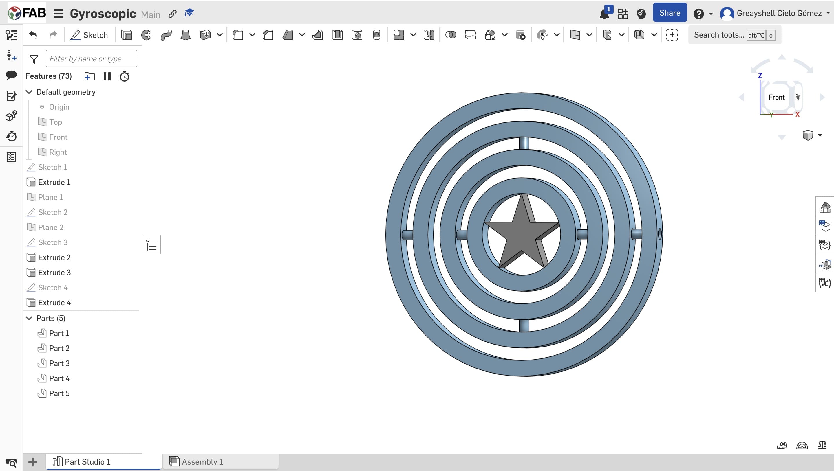
04. Central Star
A total of four concentric rings were created. However, in the central ring, a star-shaped geometry was incorporated, traced from an imported reference image and then adjusted to the internal diameter of the ring.
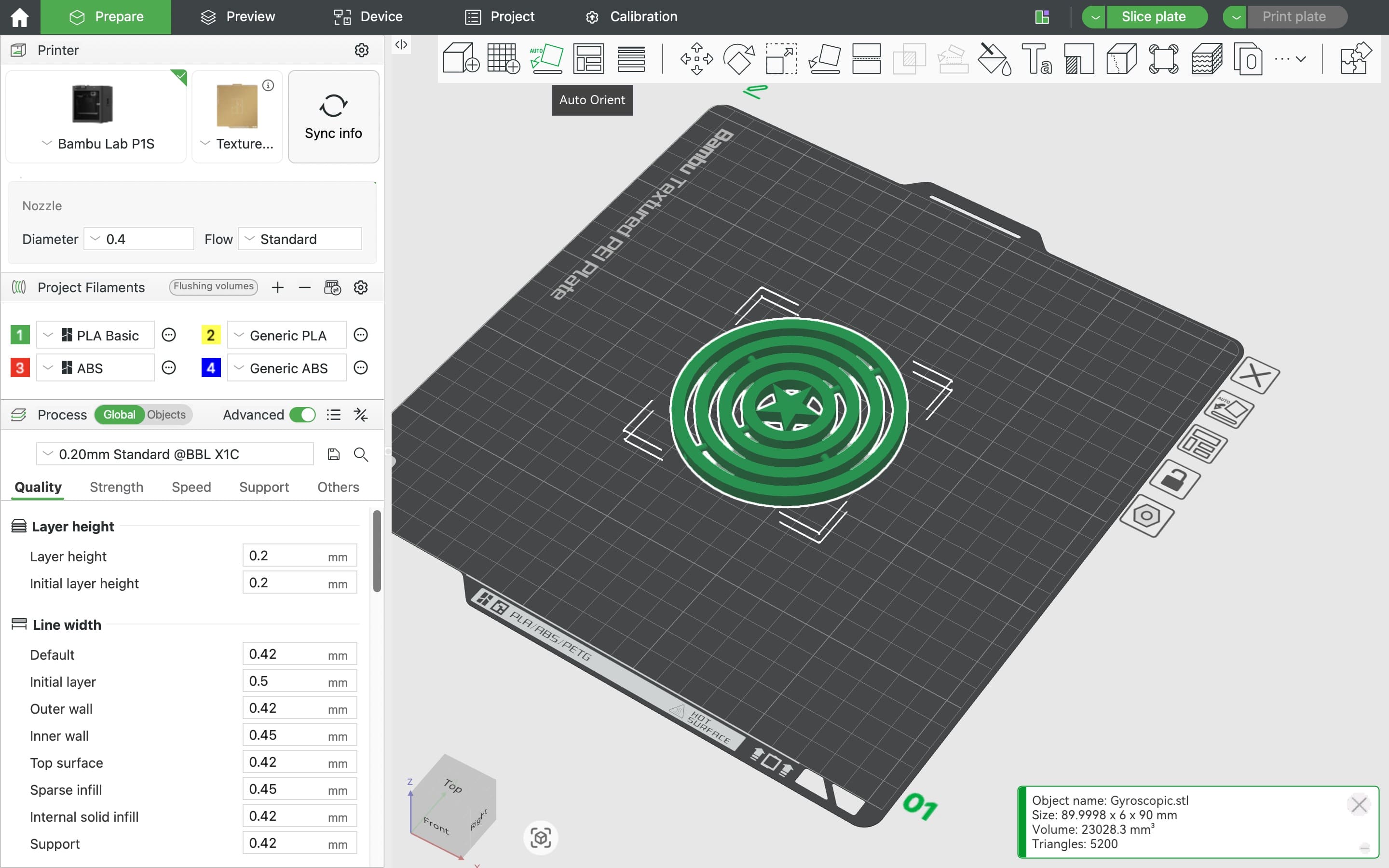
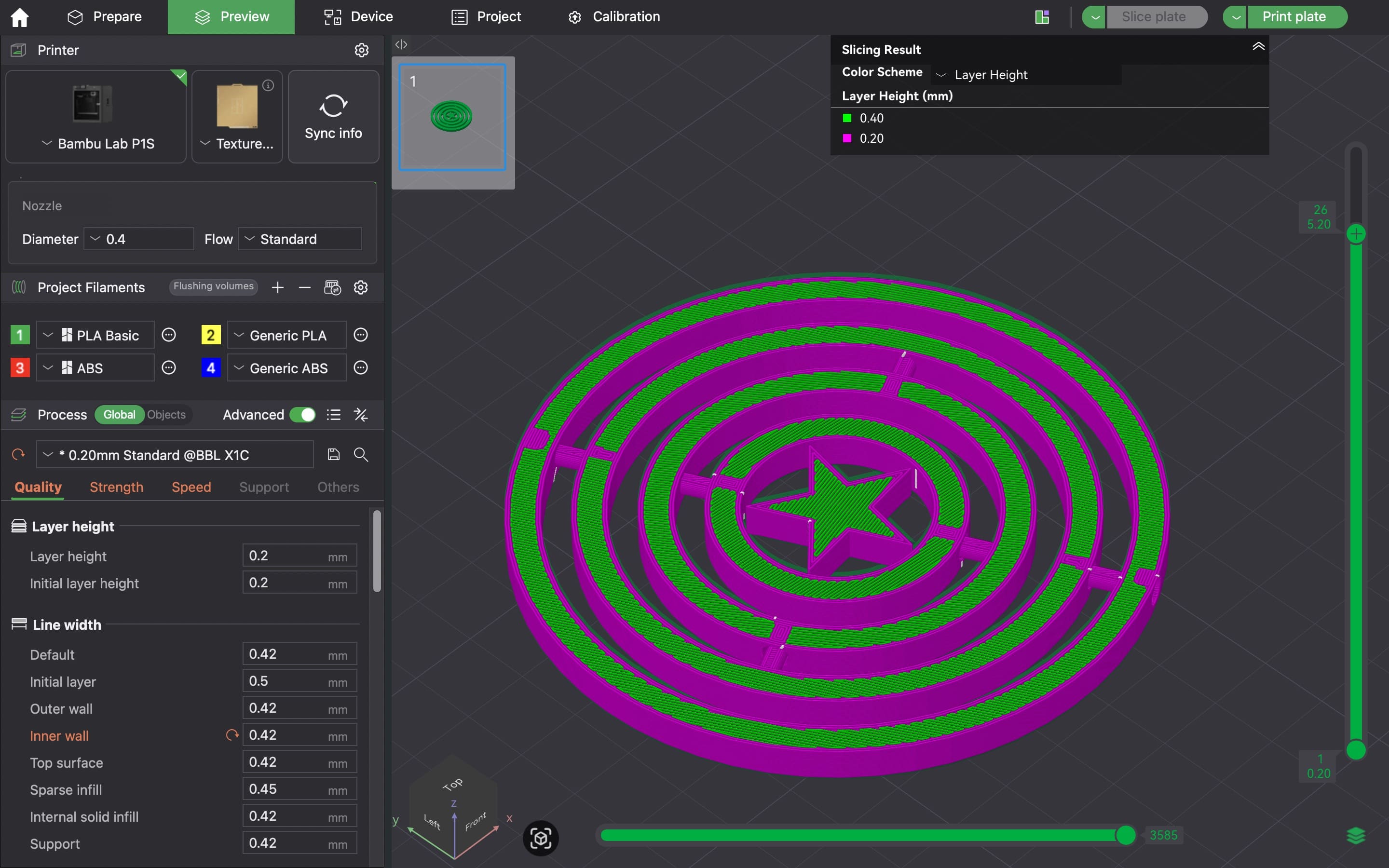
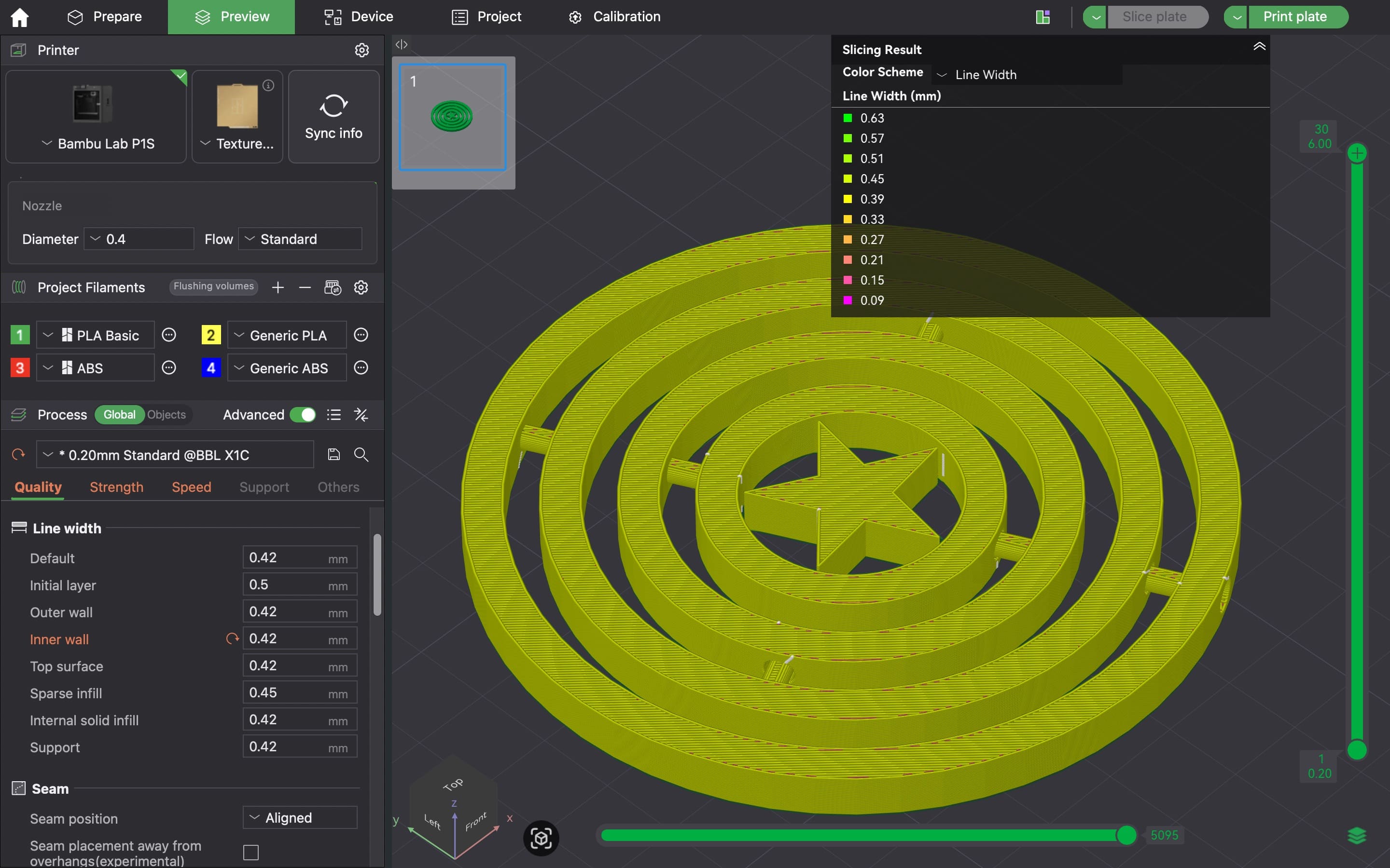
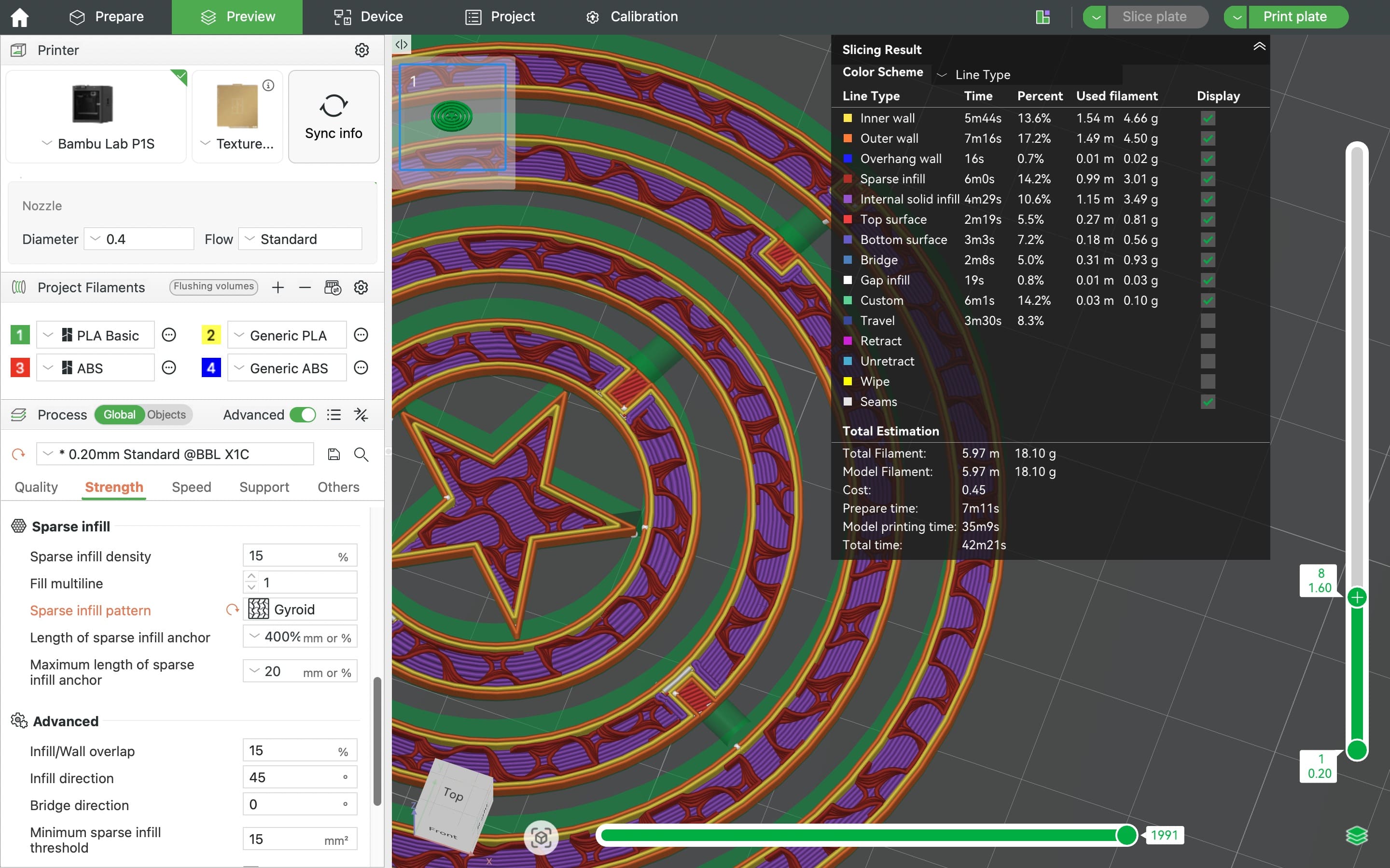
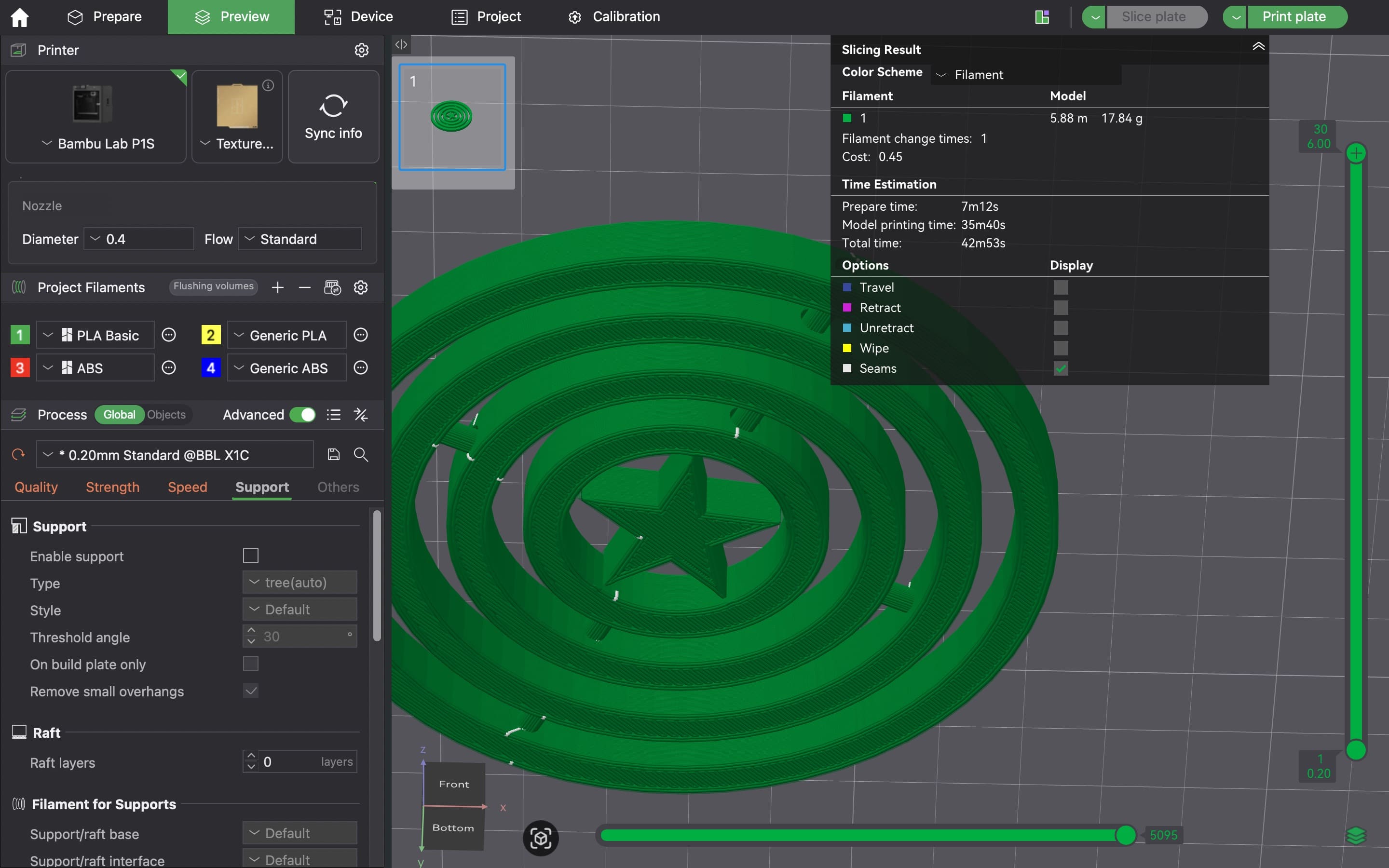
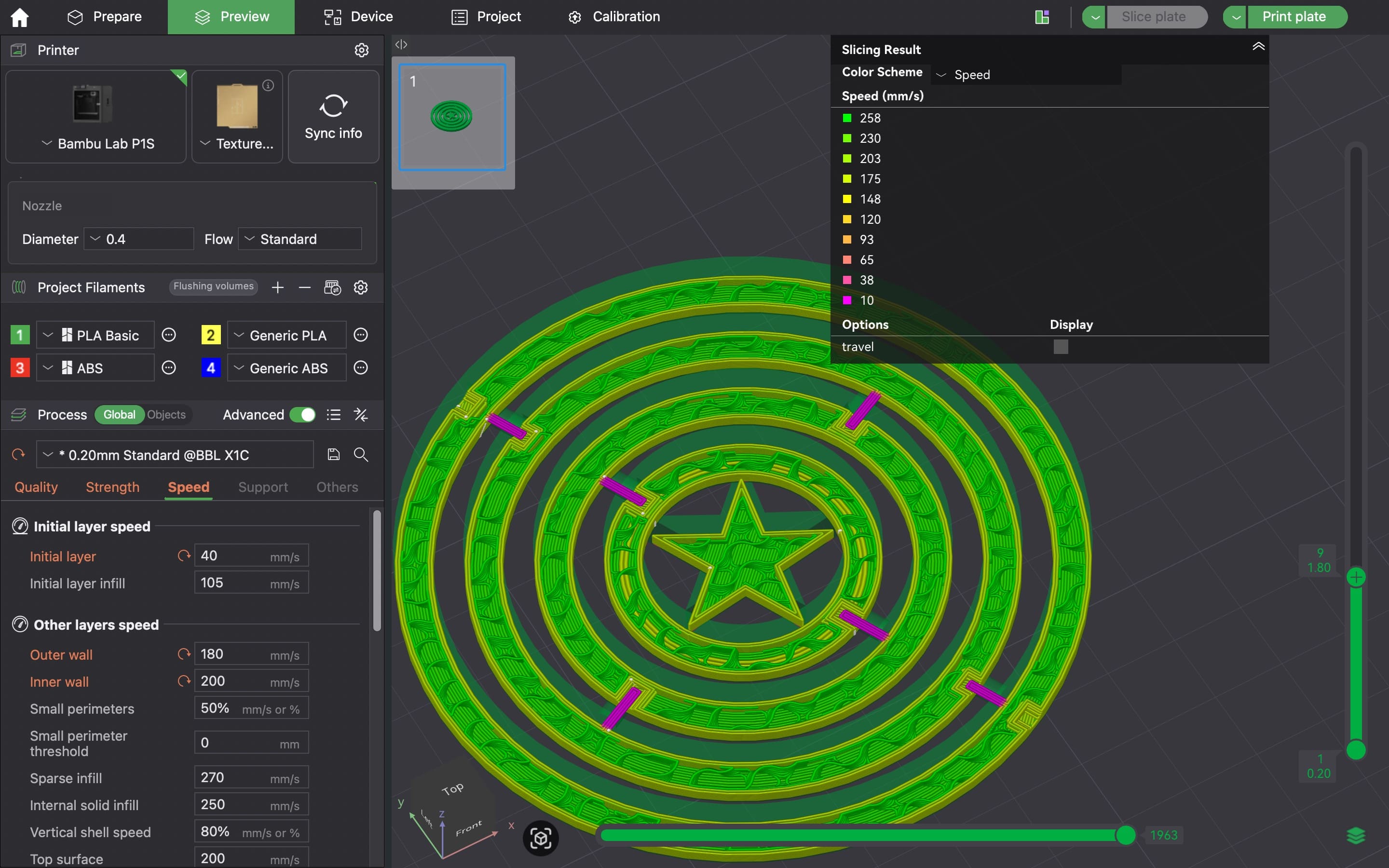
Printing Setup and Configuration
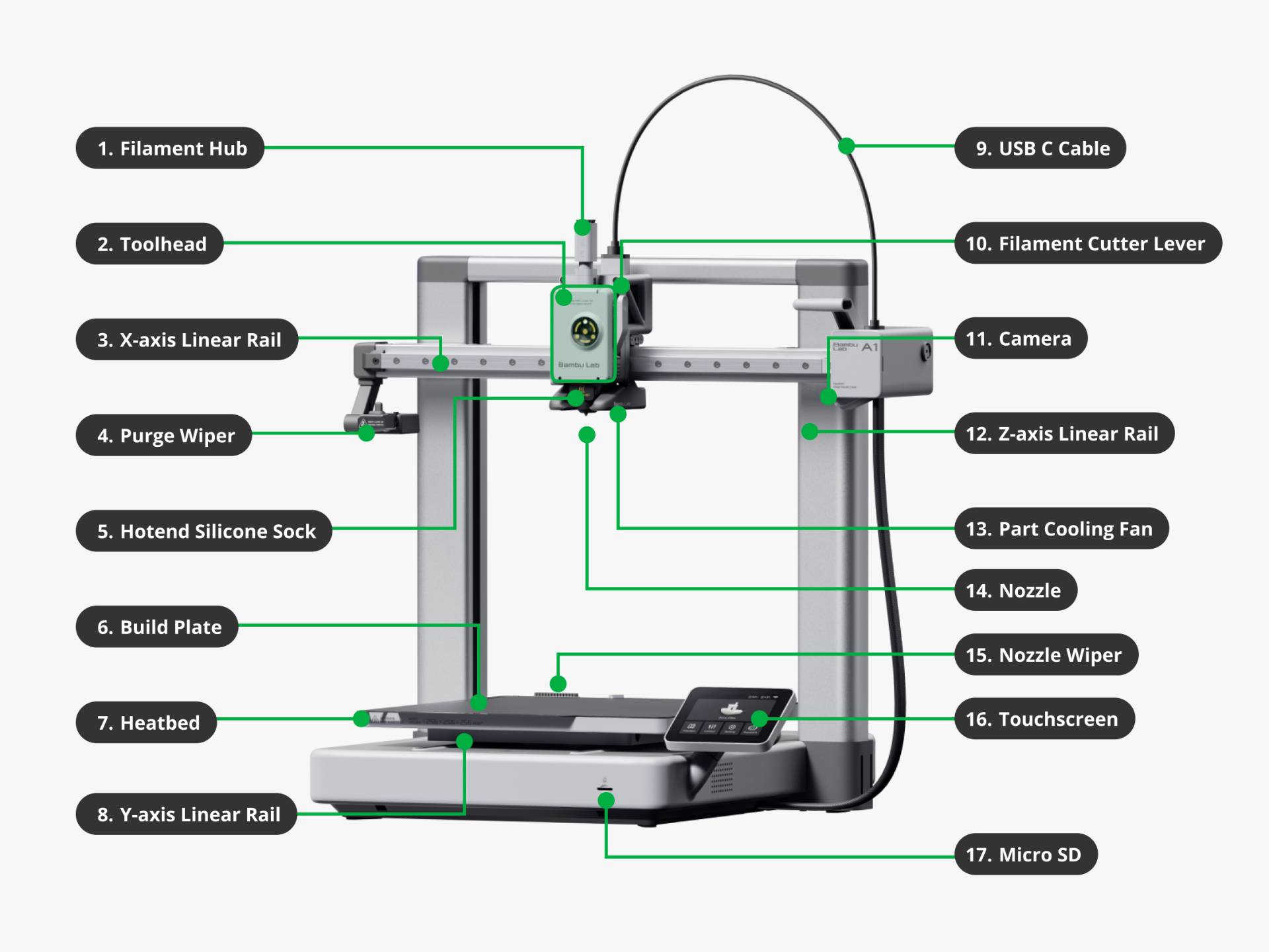
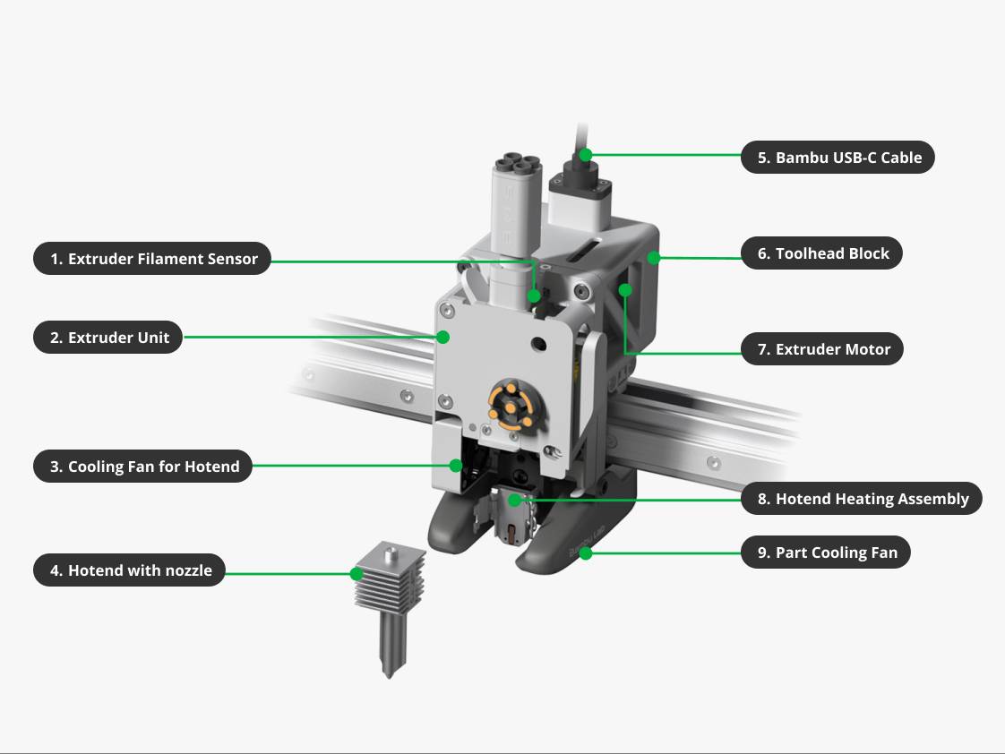
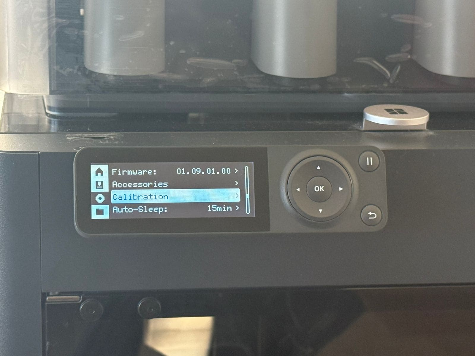
The final model will be printed using a Bambu Lab P1S, and the print parameters will be carefully configured in Bambu Studio to ensure optimal results.
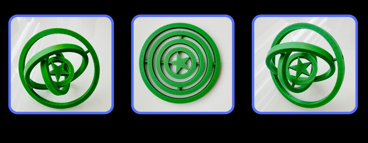
Final Result - 3D Prinitng
3D Scanning
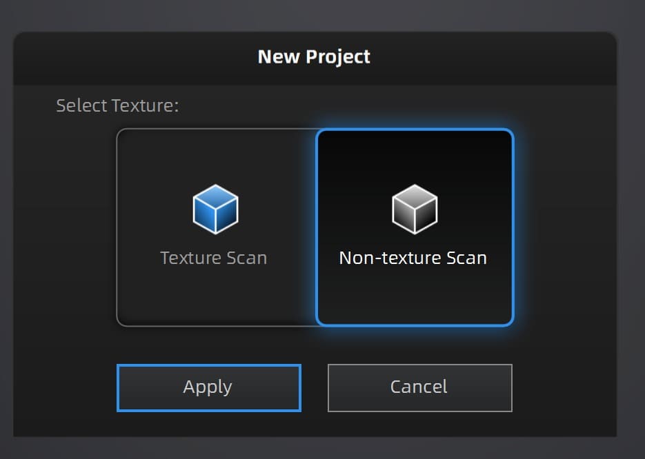
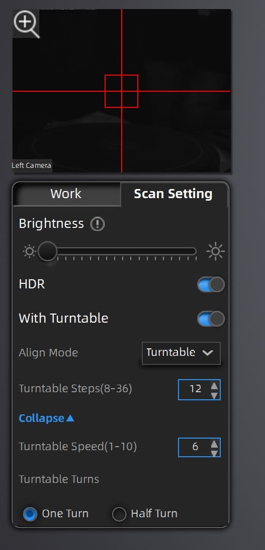
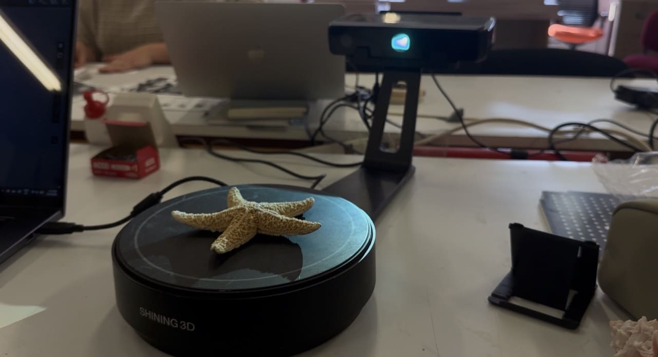
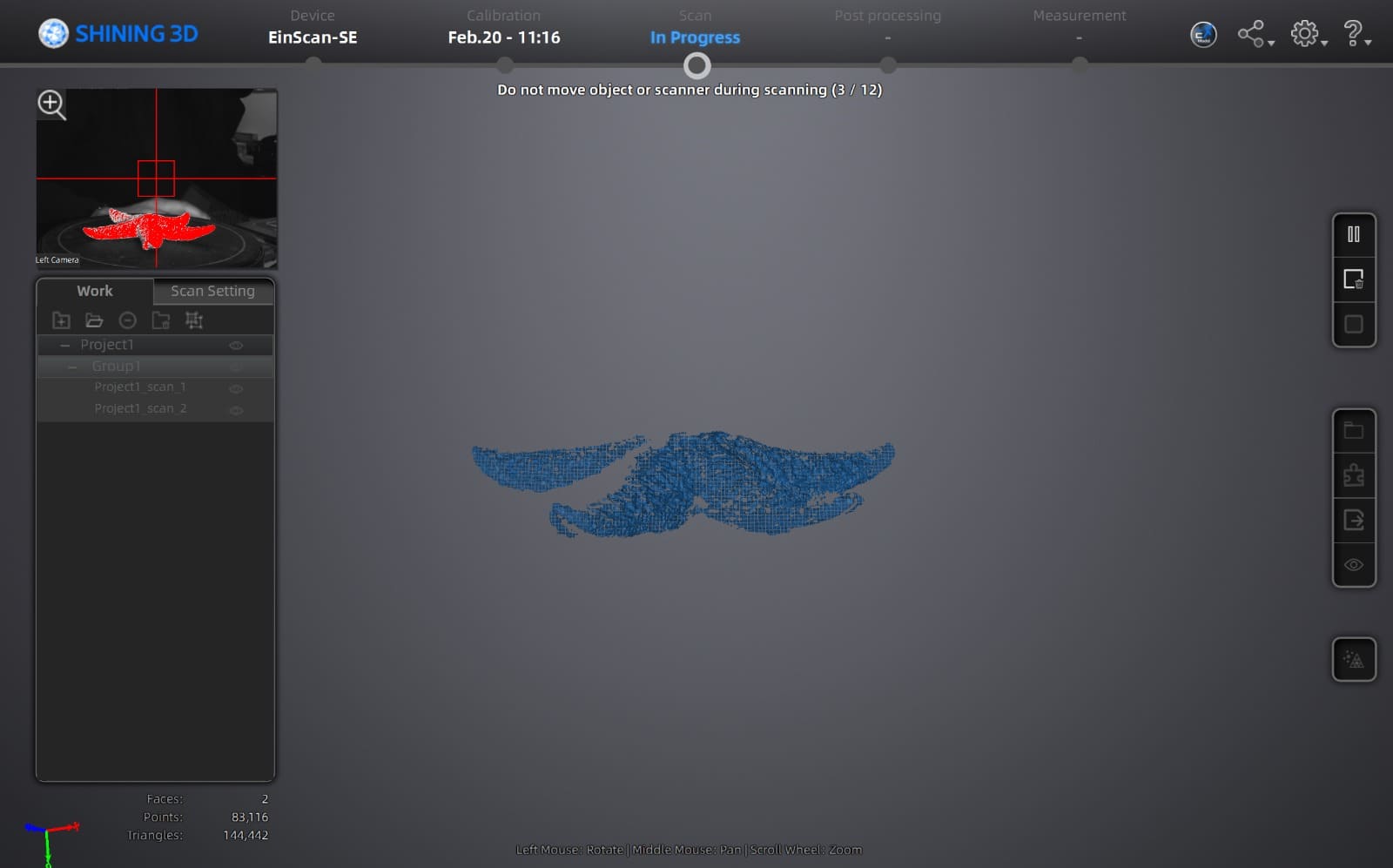
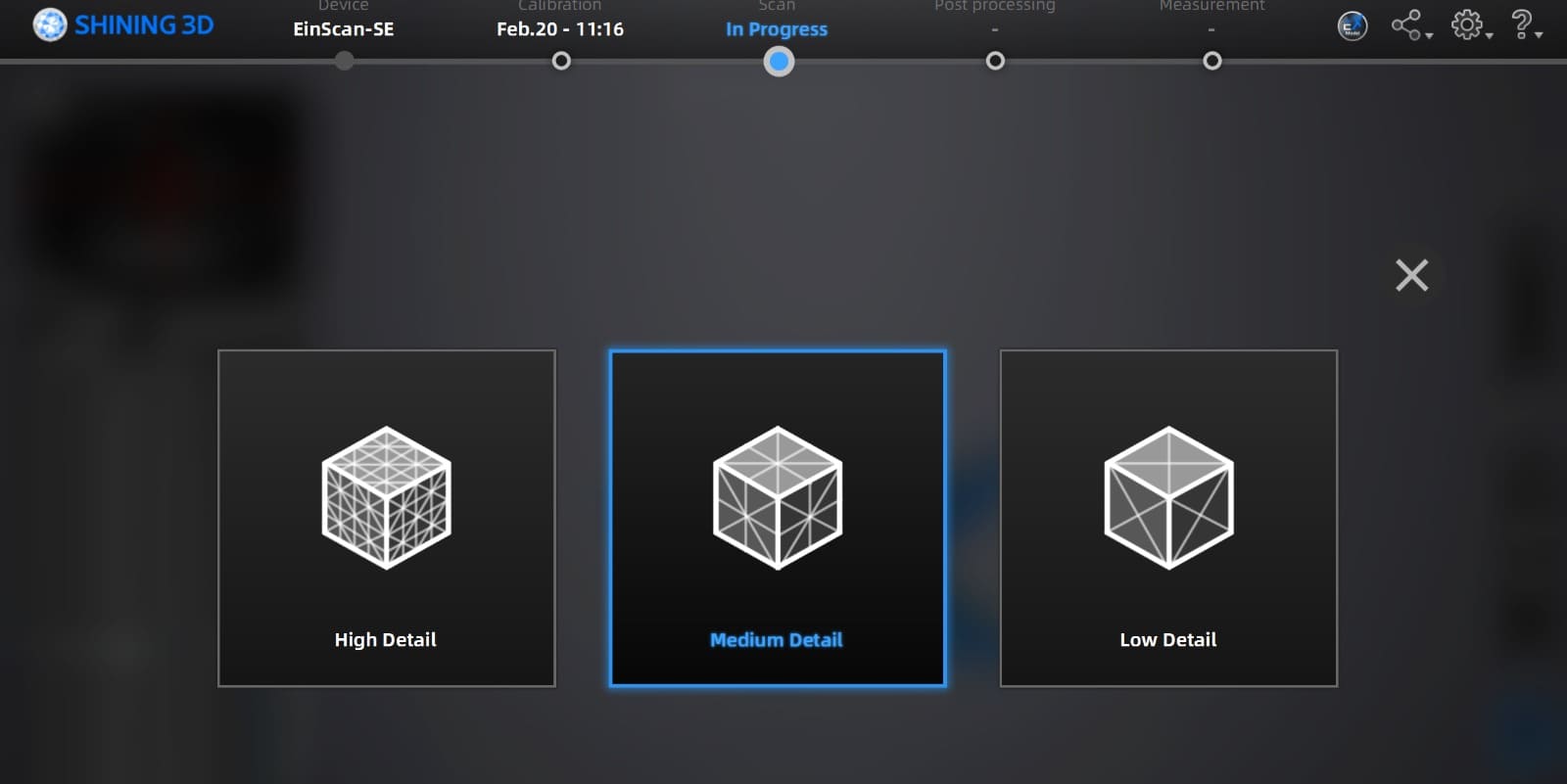
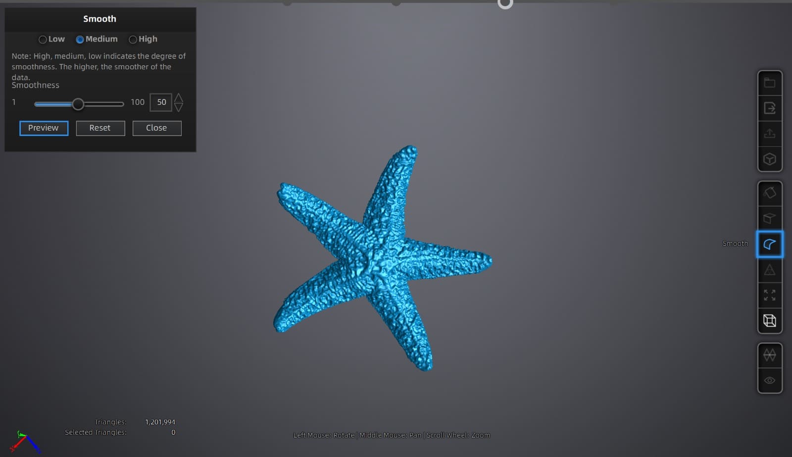
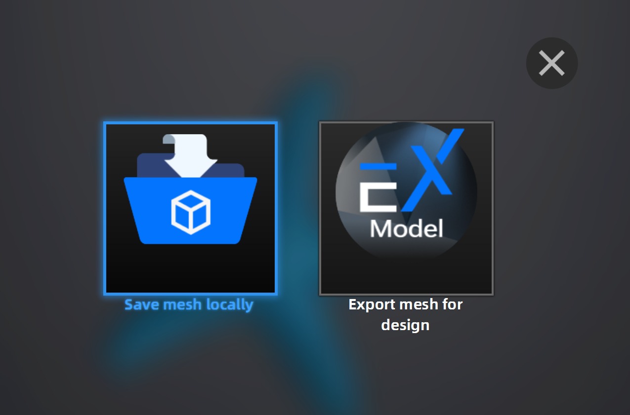
I performed a 3D scan of a starfish using the EinScan-SE scanner. The objective was to understand the complete scanning workflow: from scan configuration to mesh processing.
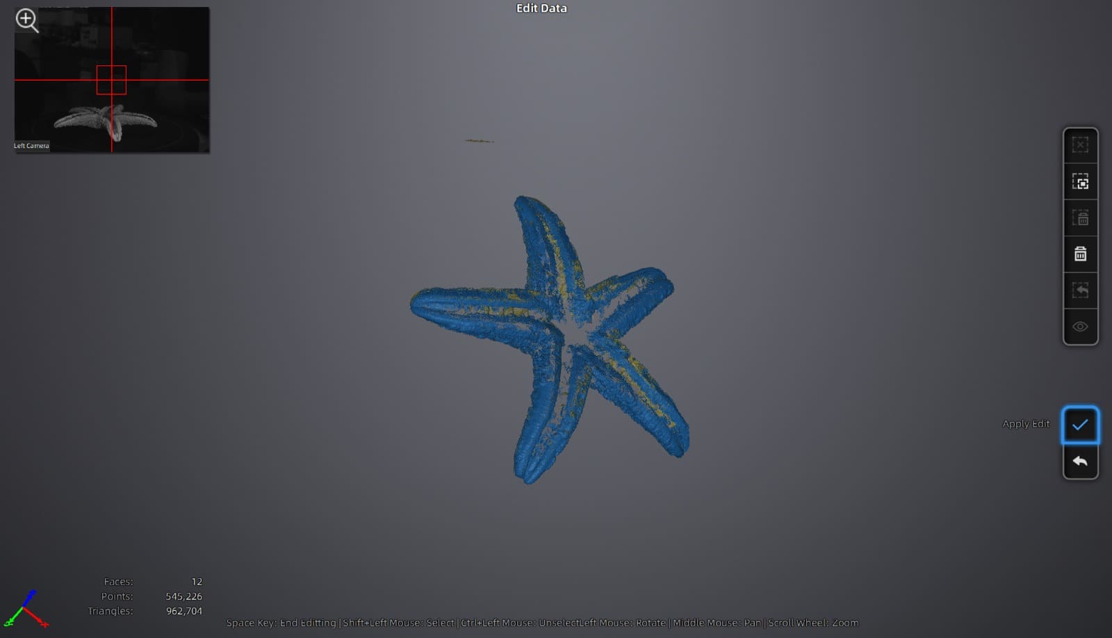
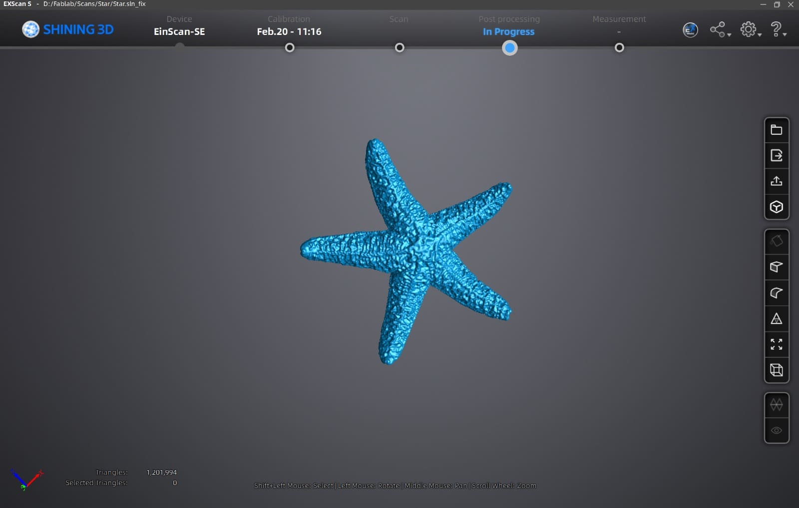
Final Result - 3D Scanning
Final Thoughts
Week 5 helped me understand digital fabrication from both creation and capture. Designing and printing the gyroscope showed me how crucial tolerances, orientation, and print settings are for functional results, while scanning the starfish highlighted the importance of proper calibration and configuration. This week I learned that successful fabrication depends not only on the design itself, but on understanding and adjusting the machines and parameters behind the final result.
Download Here!
In this section, you can find the downloadable source files developed during this week.