Week 04 - Embedded Programming#
Week 4 focused on embedded programming, learning to program microcontrollers and understand how software controls hardware at a low level.
The aim was to read data sheets, write code for embedded systems, and establish communication between the microcontroller and input/output devices.
Group Assignment#
- Demonstrate and compare the toolchains and development workflows for available embedded architectures
Individual Assignment#
- Browse through the data sheet for a microcontroller
- Write and test a program for an embedded system using a microcontroller to interact with local input &/or output devices and communicate with remote wired or wireless connections
Extra Credit Goals
- Assemble your own embedded system
- Try different programming languages &/or development environments
What I Learned#
This week helped me understand how embedded systems actually work beyond just writing code. I learned how to set up and program microcontrollers using both Arduino IDE and alternative environments, and how different workflows (like standalone systems vs PC-based development) affect the development process.
I also learned how to interface hardware with software — from running simple programs to executing more complex applications like game logic and display control. Debugging was a big part of the process, and I got better at identifying issues related to compilation, libraries, and hardware connections.
Overall, this week showed me that embedded programming is not just about code, but about understanding the complete system — hardware, software, and how they interact in real time.
Software Used#
- Arduino IDE for programming
- Development environment for the microcontroller
- Serial monitor for debugging and communication
- Visual Studio Code + Git for documentation
- App Lab for programming in App Lab
- Thonypython for programming in MicroPython
- Firebase for cloud communication
Weekly Schedule#
| Day | What I Did |
|---|---|
| WED | Lecture on embedded programming |
| THU | Understanding what embedded programming is and the difference between microcontroller and microprocessor |
| FRI | Going through the data sheet of microcontroller |
| SAT | Cretating Embedded Program for SeedStudio Xiao RP2040 |
| SUN | Figuring out MicroPython on RP2040 and playing around with Arduino Q |
| MON | Assembling and testing a simple Embedded system |
| TUE | Regional review |
Group Assignment - Toolchains and Development Workflows#
I’m adding the group assignment page here for reference:
🔗 https://fabacademy.org/2026/labs/kochi/group_assignmetns/week04/
🧠 Introduction – What is Embedded Programming?#
This week started with understanding what embedded programming really is.
Embedded programming is the process of writing software that runs on a microcontroller or embedded system designed to perform a dedicated task.
Unlike general-purpose computers (like laptops or desktops), embedded systems:
- Are built for specific applications
- Directly interact with hardware components
- Have limited memory and processing power
- Often operate in real-time environments
- Must be efficient, stable, and reliable**
Examples of embedded systems include:
- Washing machine controllers
- Car engine control units (ECUs)
- Smart watches
- Remote controls
- Industrial automation systems
- IoT sensor nodes
Embedded programming connects the physical world (sensors, motors, voltage signals) with digital logic and code execution.
🔬 Hardware Fundamentals – From Physics to Logic#
To truly understand embedded programming, I must understand the hardware foundation beneath it.
🔌 Transistors – The Building Blocks of Everything#
A transistor can be compared to a water tap.
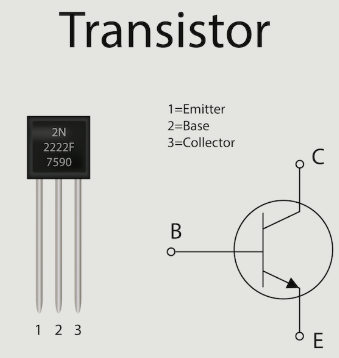
It typically has three terminals:
- Input
- Output
- Control (Gate/Base)
Water Tap Analogy:#
- Input → Water source
- Output → Flowing water
- Control → Tap handle
When the control is activated → current flows.
When the control is inactive → no current flows.
Therefore, a transistor acts like a switch.
It has two states:
- ON → 1
- OFF → 0
This is called binary logic.
Modern microcontrollers contain millions or even billions of transistors, all working together as tiny switches.
Logic Gates – Decision Making Using Transistors#
When multiple transistors are connected in series or parallel configurations, they form logic gates.
Logic gates take binary inputs and produce binary outputs.
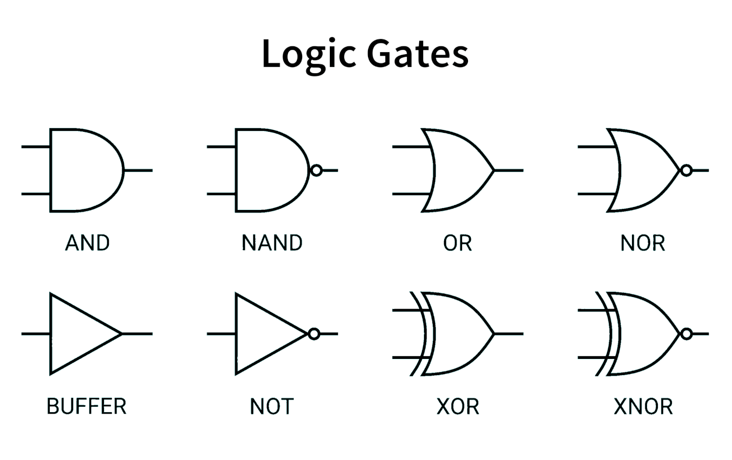
🔹 AND Gate#
Output is 1 only if both inputs are 1.
| A | B | Output |
|---|---|---|
| 0 | 0 | 0 |
| 0 | 1 | 0 |
| 1 | 0 | 0 |
| 1 | 1 | 1 |
🔹 OR Gate#
Output is 1 if at least one input is 1.
| A | B | Output |
|---|---|---|
| 0 | 0 | 0 |
| 0 | 1 | 1 |
| 1 | 0 | 1 |
| 1 | 1 | 1 |
🔹 NOT Gate#
Inverts the input.
| A | Output |
|---|---|
| 0 | 1 |
| 1 | 0 |
🔹 XOR Gate (Exclusive OR)#
Output is 1 only when inputs are different.
| A | B | Output |
|---|---|---|
| 0 | 0 | 0 |
| 0 | 1 | 1 |
| 1 | 0 | 1 |
| 1 | 1 | 0 |
➕ Binary Adders – How Computers Perform Arithmetic#
Inside a CPU, arithmetic is done using logic gates.
Half Adder#
https://www.geeksforgeeks.org/digital-logic/half-adder-in-digital-logic/
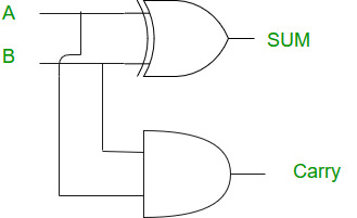
Inputs:
- A
- B
Outputs:
- Sum
- Carry
Logic:
- Sum = A XOR B
- Carry = A AND B
Full Adder#
https://www.geeksforgeeks.org/digital-logic/full-adder-in-digital-logic/
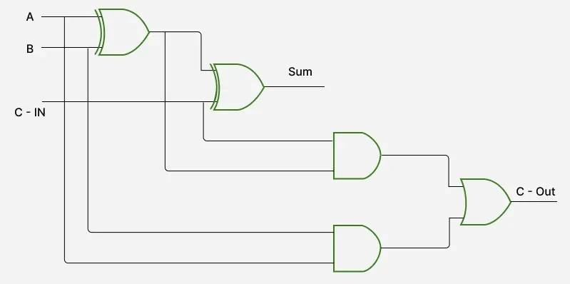
Adds:
- A
- B
- Carry-in
This allows addition of multi-bit numbers by chaining full adders together.
This is the foundation of arithmetic inside processors.
🔢 Bits, Bytes and Memory#
- 1 bit = 0 or 1
- 8 bits = 1 byte
- 1024 bytes = 1 KB
Examples:
- 1 byte stores values from 0–255
- 4 bytes (32 bits) store larger integers
- Memory in microcontrollers is measured in KB, not GB
Memory is limited and must be used efficiently.
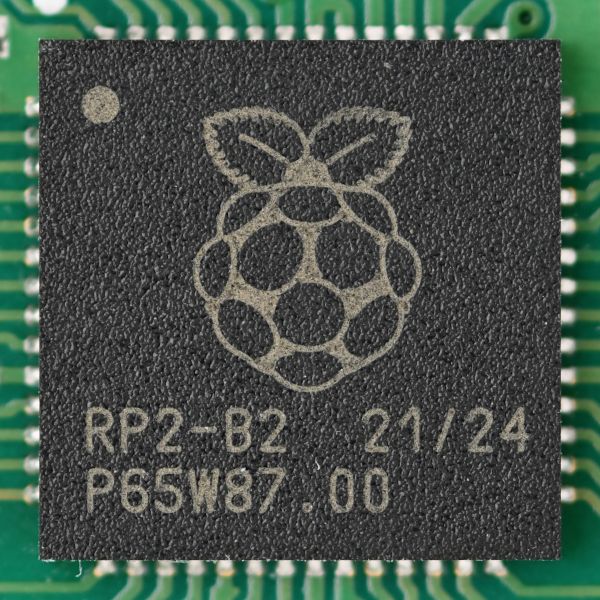
📘 Datasheet Study – RP2040#
This week I explored the datasheet of the RP2040 microcontroller.
Official Datasheet:
https://pip-assets.raspberrypi.com/categories/814-rp2040/documents/RP-008371-DS-1-rp2040-datasheet.pdf
RP2040 Overview#
- Dual-core ARM Cortex-M0+ microcontroller
- Designed by Raspberry Pi
- Used in Raspberry Pi Pico and many custom boards
- 133 MHz maximum clock frequency
- 264 KB SRAM
- External QSPI Flash
- No built-in WiFi or Bluetooth
- Rich peripheral set
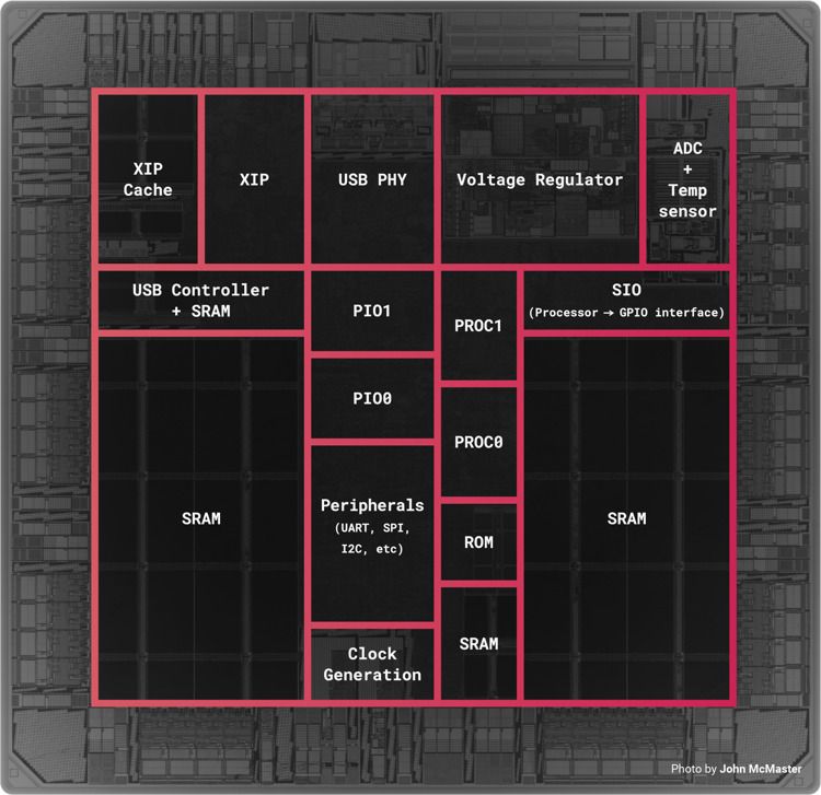
Architecture Breakdown#
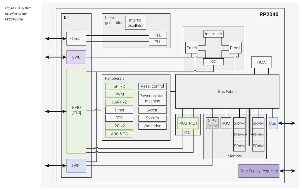
Dual ARM Cortex-M0+ Cores#
- Two processors running up to 133 MHz
- Can execute tasks in parallel
- Share memory and peripherals
Shared SRAM#
- 264 KB SRAM divided into banks
- Accessible by both cores
- Stores runtime variables, stack and heap
Bus Fabric#
- Connects CPU cores, memory and peripherals
- Manages internal data flow
DMA Controller#
- Direct Memory Access
- Transfers data without CPU involvement
- Improves efficiency and reduces processing load
USB Controller#
- USB 1.1 device support
- Enables serial communication and USB-based applications
PIO (Programmable I/O)#
Unique RP2040 feature:
- 2 PIO blocks
- 4 state machines each
- Allows custom hardware protocols
- Used for advanced interfaces like NeoPixels or VGA output
ADC#
- 12-bit resolution
- Converts analog voltage to digital data
Timers#
Used for:
- Delays
- PWM generation
- Scheduling and timing operations
🧠 Memory Architecture#
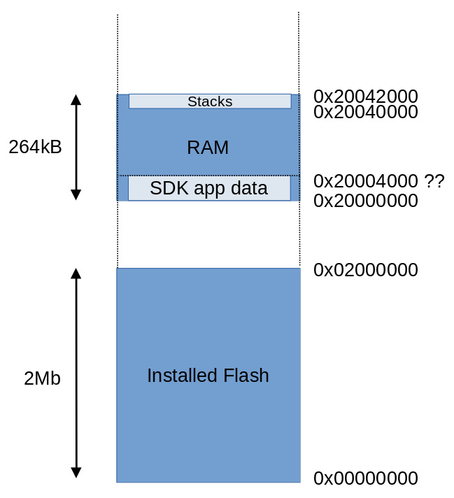
From the datasheet:
- 264 KB SRAM divided into banks
- No internal flash
- Uses external QSPI flash
- Supports XIP (Execute in Place)
Explanation#
- Program code runs directly from external flash (XIP)
- SRAM stores stack, heap and variables
- Peripherals are memory-mapped
Memory-mapped means hardware registers appear as memory addresses.
Writing to specific memory locations controls hardware directly.
GPIO & Peripheral System#
GPIO#
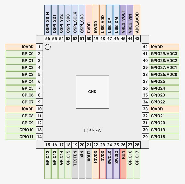
- 30 GPIO pins (on Pico board)
- Multiple alternate functions per pin
- Digital input/output
- PWM capable
- Interrupt capable
Available Peripherals#
- 2 × UART
- 2 × SPI
- 2 × I2C
- USB 1.1 controller
- 12-bit ADC
- 16 PWM channels
- DMA controller
These peripherals allow communication and interaction with external hardware devices.
Basics of Embedded Programming (Arduino Style)#
void setup()#
- Runs once at startup
- Used for initialization
- Configures pins and peripherals
void loop()#
- Runs continuously after setup
- Contains main program logic
#define#
- Preprocessor directive
- Defines constants before compilation
int#
- Stores integer values
- Typically 32-bit on RP2040
float#
- Stores decimal values
- Uses more memory than int
bool#
- Stores true or false
- Used for logical conditions and state control
Functions#
Reusable blocks of code that improve modularity and organization.
delay()#
Pauses execution for specified milliseconds.
Note: It blocks CPU execution.
Serial.print()#
Used for debugging and monitoring via Serial Monitor.
🔑 Additional Important Programming Concepts#
pinMode()#
Configures pin as INPUT or OUTPUT.
digitalRead()#
Reads digital value from a pin.
digitalWrite()#
Writes HIGH or LOW to a pin.
analogRead()#
Reads analog input via ADC.
PWM (Pulse Width Modulation)#
Simulates analog output using digital pulses.
Conditional Statements#
if, else statements control logic flow.
Loops#
for and while loops repeat instructions.
Interrupts#
Allow hardware events to interrupt normal code execution.
My Journey Through Embedded Programming#
Platforms Explored#
- RP2040 using Arduino IDE
- RP2040 using MicroPython
- Arduino UNO Q
- ESP32-C6
🟣 Part 1 – RP2040 Using Arduino IDE#
I started off with the RP2040 using the Arduino IDE, since I already had Arduino IDE installed and was familiar with its workflow.
Step 1 – Installing Arduino IDE#
Since I already had it installed, I directly opened it.
If not installed, the software can be downloaded from the official Arduino website:
https://www.arduino.cc/en/software
After downloading:
- Install the IDE
- Open it
- Verify it launches correctly
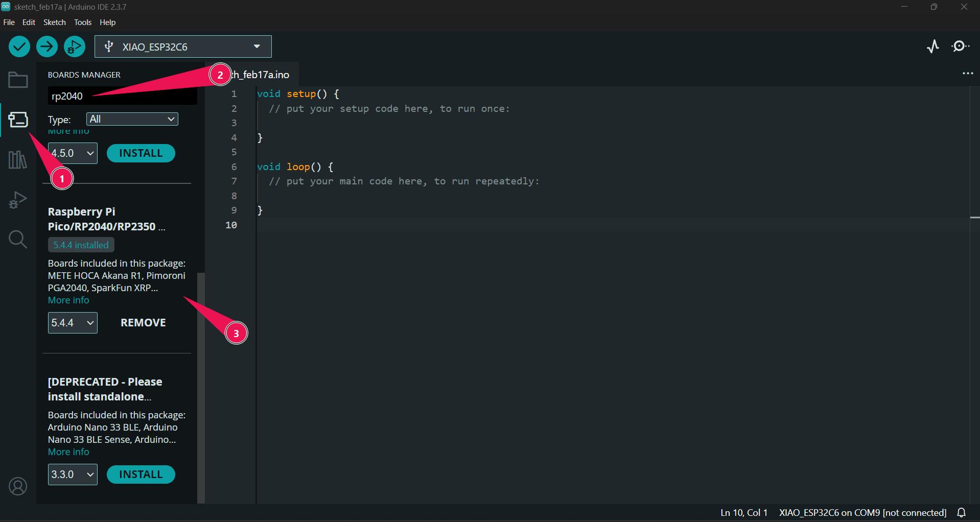
Step 2 – Adding RP2040 Board Support#
By default, Arduino IDE does not include RP2040 board definitions.
I need to install the required board package.
For this, I referred to the Seeed Studio Getting Started Guide for:
- XIAO RP2040
- XIAO ESP32-C6
Guide used:
👉 https://wiki.seeedstudio.com/XIAO-RP2040/
Steps to Add Board Configuration#
- Open Arduino IDE
- Go to: File → Preferences
- In the Additional Boards Manager URLs field, add:
https://github.com/Seeed-Studio/Arduino_Boards/raw/master/Seeed%20RP2040/package_seeed_board_index.json - Click OK

- Go to: Tools → Board → Boards Manager
- Search for “RP2040” and install the board package
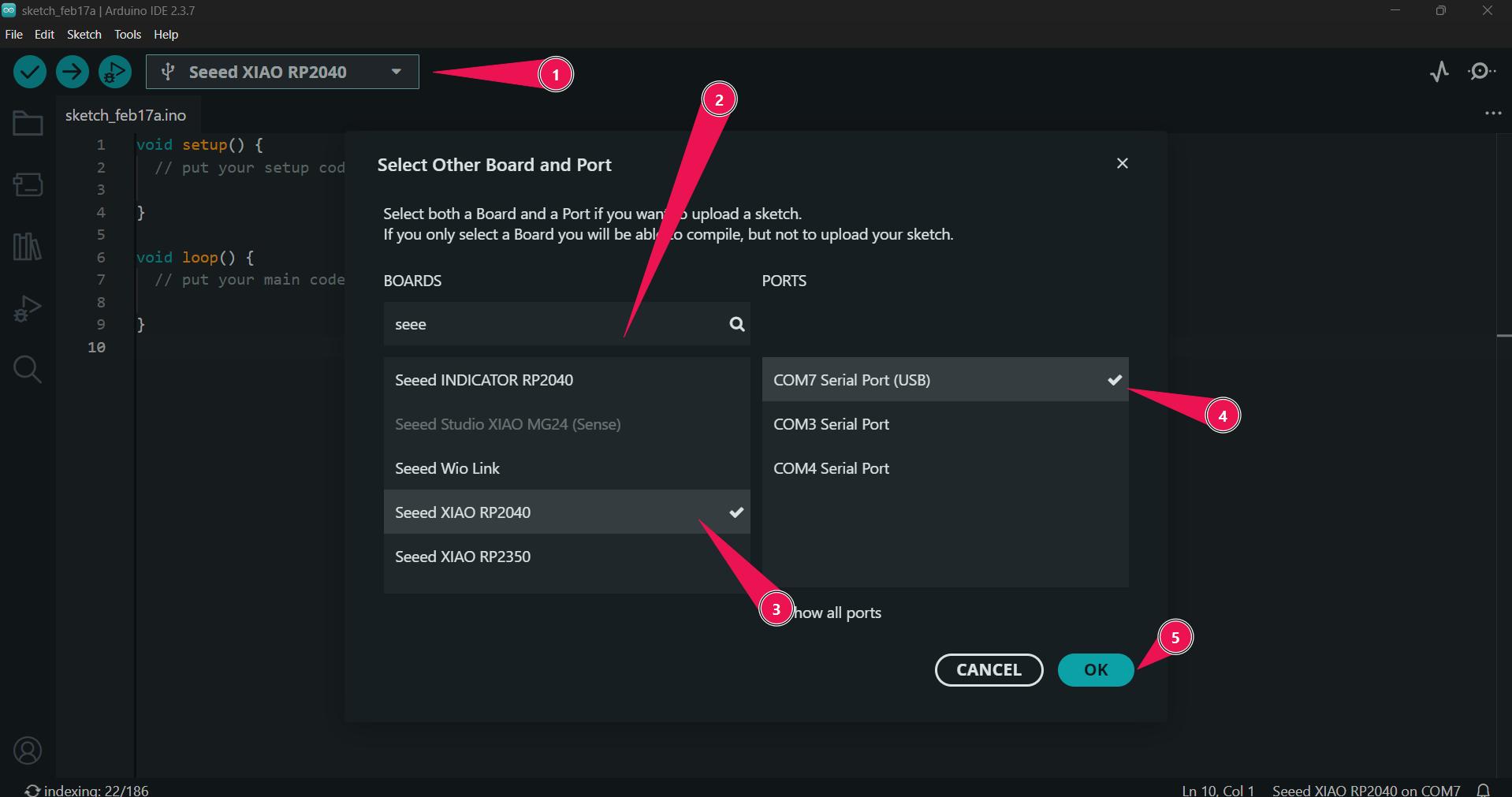
Selecting the Correct Board#
After installing the required board package:
Go to:
Tools → BoardSelect:
Seeed XIAO RP2040
Then:
- Connect the board via USB
- Select the correct COM port from:
Tools → Port
Make sure the correct port appears after plugging in the board. If it does not appear, check:
- USB cable (data cable, not power-only)
- Drivers
- Bootloader mode (if needed)
🔄 Development Workflow (Arduino + RP2040)#
The development workflow followed:
- Write code
- Verify (compile)
- Upload
- Monitor output using Serial Monitor
This workflow is:
- Simple
- Structured
- Beginner-friendly
- Fast for prototyping
🧪 Experiments with RP2040 Using Arduino IDE#
After successfully setting up the RP2040 with the Arduino IDE, I started experimenting with different programs to better understand GPIO control, timing patterns, RGB LEDs, button input, and serial communication.
Below are the experiments I carried out during this process.
🔹 1️⃣ Modified Blink Code (RP2040)#
The first thing I did was modify the existing Arduino Blink example to work properly with the RP2040 board.
Since different boards may have different built-in LED pin definitions, I adjusted the code accordingly to ensure compatibility with the RP2040.
This helped me understand:
- How
pinMode()configures a pin as OUTPUT - How
digitalWrite()controls HIGH and LOW states - How
delay()controls timing - The compile → upload → test workflow
💻 Code#
#define USER_LED_R 17 // defined the xiao pin to the chip pin
void setup() {
  pinMode(USER_LED_R, OUTPUT); // intialised the red pin as output , so the power will be provided
}
void loop() {
  digitalWrite(USER_LED_R, HIGH);  // turn the LED on (HIGH is the voltage level)
  delay(1000);                      // wait for a second
  digitalWrite(USER_LED_R, LOW);   // turn the LED off by making the voltage LOW
  delay(1000);                      // wait for a second
}
📸 Output#
The onboard LED blinked successfully, confirming that:
- The board configuration was correct
- The upload process was working
- The microcontroller was executing the program properly
✈️ 2️⃣ Boeing vs Airbus Light Pattern Simulation#
After this, I had a conversation with my instructor Mr. Saheen Palayi .
He mentioned an interesting real-world observation:
The blinking patterns of aircraft lights differ between planes manufactured by Boeing and Airbus.
This encouraged me to experiment with different blinking sequences and simulate unique light signatures using timing variations.
The idea was to replicate:
- Fast double-blink patterns
- Slower single-blink patterns
- Different delay intervals to mimic real aircraft lighting styles
This exercise helped me understand how embedded systems can be used to create recognizable signal patterns through precise timing control.
💻 Code#
#define USER_LED_R 17 // defined the xiao pin to the chip pin
#define USER_LED_B 25
#define USER_LED_G 16
void setup() {
  pinMode(USER_LED_R, OUTPUT); // intialised the red pin as output , so the power will be provided
  pinMode(USER_LED_B, OUTPUT);
  pinMode(USER_LED_G, OUTPUT);
}
void loop() {
  digitalWrite(USER_LED_R, HIGH);  // turn the LED on (HIGH is the voltage level)
  delay(1000);                      // wait for a second
  digitalWrite(USER_LED_R, LOW);   // turn the LED off by making the voltage LOW
  delay(1000);                      // wait for a second

  digitalWrite(USER_LED_B, HIGH);
  delay(1000);
  digitalWrite(USER_LED_B, LOW);
  delay(1000);

  digitalWrite(USER_LED_G, HIGH);
  delay(1000);
  digitalWrite(USER_LED_G, LOW);
  delay(1000);
}
📸 Output#
Through this experiment, I learned:
- Timing precision is important in embedded systems
- Human perception can distinguish between subtle blinking differences
- Delay-based pattern design is simple but powerful
🚨 3️⃣ Police Lights Using Built-in NeoPixel#
Next, I experimented with the built-in NeoPixel available on the RP2040 board.
The goal was to simulate police lights using alternating red and blue colors.
This introduced new concepts such as:
- RGB color control
- Using external libraries (NeoPixel library)
- Managing timing for visual effects
- Controlling addressable LEDs
Instead of just turning an LED ON or OFF, this allowed color mixing and more dynamic light behavior.
💻 Code#
#include <Adafruit_NeoPixel.h>

#define PIN_NEOPIXEL 12  // Data pin
#define PIN_POWER    11  // Power pin (Enable)
#define NUM_PIXELS   1   // XIAO has 1 built-in NeoPixel

// Initialize the library
Adafruit_NeoPixel pixel(NUM_PIXELS, PIN_NEOPIXEL, NEO_GRB + NEO_KHZ800);

void setup() {
  pinMode(PIN_POWER, OUTPUT);
  digitalWrite(PIN_POWER, HIGH); // Power on the NeoPixel
  pixel.begin();
  pixel.setBrightness(55); // 0-255
}

void loop() {
  pixel.setPixelColor(0, pixel.Color(255, 0, 0)); // Red
  pixel.show();
  delay(500);

  pixel.setPixelColor(0, pixel.Color(0, 0, 0)); // Green ← Fixed!
  pixel.show();
  delay(500);

  pixel.setPixelColor(0, pixel.Color(0, 0, 255)); // Blue
  pixel.show();
  delay(500);

  pixel.setPixelColor(0, pixel.Color(0, 0, 0)); // Off
  pixel.show();
  delay(500);
}
📸 Output#
This experiment helped me understand:
- How RGB values combine to create different colors
- How embedded systems control smart LEDs
- How libraries abstract low-level hardware control
🔵⚪🔴 4️⃣ External LEDs + Button + Serial Monitor#
After working with the onboard components, I moved to external hardware.
I connected:
- 🔵 Blue LED
- ⚪ White LED
- 🔴 Red LED
These represent the French flag colors.
Each LED was connected with a 1kΩ resistor as a current-limiting resistor to protect the LEDs from excessive current.
I also added:
- A push button as digital input
- Serial Monitor for debugging and output feedback
Working Logic#
- Initially, one LED is ON
- When the button is pressed, the active LED changes
- The sequence cycles through: Blue → White → Red → repeat
- Serial Monitor displays the current state
This experiment introduced:
- Digital input using a button
- Debouncing considerations
- State management using variables
- Serial debugging
- Multi-output control
💻 Code#
// Pin definitions
#define LED1 D0    // D0 → first LED (this one gonna shine first)
#define LED2 D1    // D1 → second LED
#define LED3 D2    // D2 → third LED
#define BUTTON D3  // D3 → button input (main trigger)

// Variables
int currentLED = 0;
// tracks which LED is active rn (0,1,2) and 3 = all off 😴

bool lastButtonState = HIGH;
// previous button state (HIGH = not pressed, chill state)

bool buttonState = HIGH;
// current confirmed button state after debounce

unsigned long lastDebounceTime = 0;
// last time the button changed (used to filter noise)

unsigned long debounceDelay = 50;
// 50ms cooldown so button doesn’t spam fake presses

void setup() {
  Serial.begin(9600);
  // start serial → for printing debug stuff to console

  // Set LED pins as outputs
  pinMode(LED1, OUTPUT);
  pinMode(LED2, OUTPUT);
  pinMode(LED3, OUTPUT);
  // LEDs → output because I control them

  // Set button pin as input with internal pull-up
  pinMode(BUTTON, INPUT_PULLUP);
  // default = HIGH, press = LOW (inverted logic but stable af)

  // Turn off all LEDs initially
  digitalWrite(LED1, LOW);
  digitalWrite(LED2, LOW);
  digitalWrite(LED3, LOW);
  // clean start, no random glowing nonsense

  Serial.println("System ready. Press button to cycle LEDs.");
  // just letting you know it’s alive 😎
}

void loop() {
  // Read the button state
  bool reading = digitalRead(BUTTON);
  // grab live button value

  // Check if button state changed (debounce trigger)
  if (reading != lastButtonState) {
    lastDebounceTime = millis();
    // state changed → start debounce timer
  }

  if ((millis() - lastDebounceTime) > debounceDelay) {
    // if stable for 50ms → legit press

    if (reading != buttonState) {
      buttonState = reading;
      // update official button state

      // If button was just pressed (HIGH → LOW)
      if (buttonState == LOW) {
        // button press detected 🔘

        // Turn off all LEDs first (reset everything)
        digitalWrite(LED1, LOW);
        digitalWrite(LED2, LOW);
        digitalWrite(LED3, LOW);

        // Move to next LED
        currentLED++;
        // go to next stage in the cycle

        if (currentLED > 3) {
          currentLED = 0;
          // loop back → infinite cycle 🔁
        }

        // Turn on the selected LED
        switch(currentLED) {
          case 0:
            digitalWrite(LED1, HIGH);
            Serial.println("LED 1 ON");
            // LED1 glow mode ✨
            break;

          case 1:
            digitalWrite(LED2, HIGH);
            Serial.println("LED 2 ON");
            // LED2 turn 🔥
            break;

          case 2:
            digitalWrite(LED3, HIGH);
            Serial.println("LED 3 ON");
            // LED3 flex 😎
            break;

          case 3:
            Serial.println("All LEDs OFF");
            // everyone off → nap time 😴
            break;
        }
      }
    }
  }

  lastButtonState = reading;
  // store current reading for next loop
}
📸 Output#
This final experiment combined:
- Input (button)
- Output (multiple LEDs)
- Communication (Serial Monitor)
It demonstrated a complete embedded interaction system.
🟣 Part 2 – RP2040 Using Thonny (MicroPython)#
After working with the RP2040 using the Arduino IDE, I wanted to explore a different development workflow.
This time, I used MicroPython with the Thonny IDE.
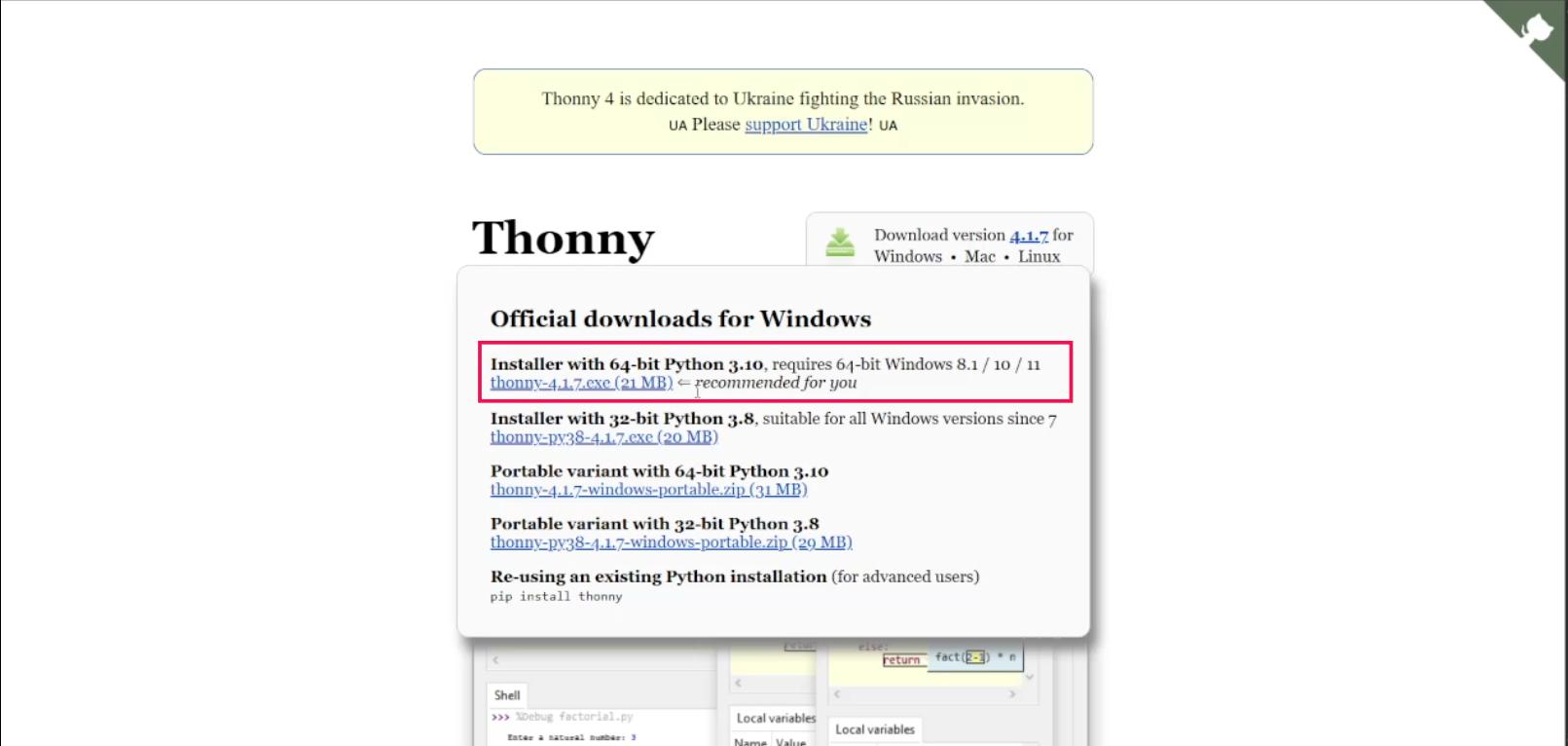
🛠 Step 1 – Installing Thonny#
I referred to the Seeed Studio wiki guide for setting up MicroPython on the XIAO RP2040.
Resources used:
Thonny Official Website:
https://thonny.org/Seeed Studio MicroPython Guide:
https://wiki.seeedstudio.com/XIAO-RP2040-with-MicroPython/
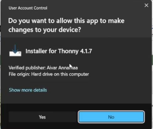
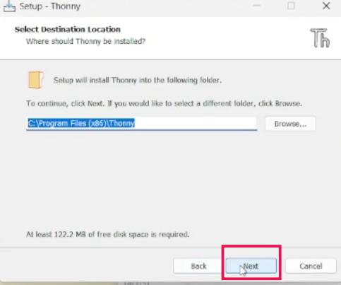
I downloaded Thonny from the official website and installed it.
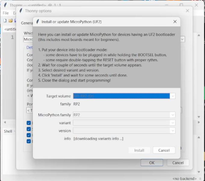
🔌 Step 2 – Flashing MicroPython Firmware#
Following the Seeed Studio guide step by step:
- Connected the RP2040 while holding the BOOT button
- The board entered bootloader mode
- A new storage device appeared
- Downloaded the appropriate MicroPython firmware file
- Dragged and dropped the firmware file onto the board
After this, the board rebooted with MicroPython installed.
⚙️ Step 3 – Configuring Thonny#
Inside Thonny:
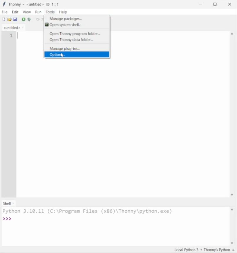
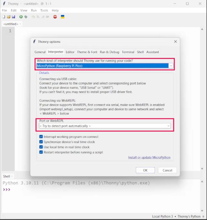
- Went to Tools → Options → Interpreter
- Selected MicroPython (Raspberry Pi Pico)
- Selected the correct COM port
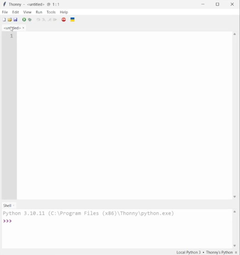
Once configured correctly, I was able to access the REPL (interactive Python shell).
💡 First Program – Blink Using MicroPython#
After setting up everything, I followed the guide and implemented the basic Blink example.
<img src="/images/week-4/thonny-8.jpg" alt="MicroPython Blink Code" style="width: 300px; border-radius: 8px;">
This was my first MicroPython program running on the RP2040.
💻 Code#
from machine import Pin, Timer

led = Pin(25, Pin.OUT)
Counter = 0
Fun_Num = 0

def fun(tim):
    global Counter
    Counter = Counter + 1
    print(Counter)
    led.value(Counter%2)

tim = Timer(-1)
tim.init(period=1000, mode=Timer.PERIODIC, callback=fun)Output#
The onboard LED blinked successfully, confirming:
- MicroPython firmware was installed correctly
- Thonny was properly configured
- Communication between PC and board was working
🔄 Arduino vs MicroPython Workflow Difference#
Arduino IDE:#
- Write code
- Compile
- Upload
- Run
MicroPython (Thonny):#
- Write Python script
- Run directly on board
- No compilation step
- Immediate execution
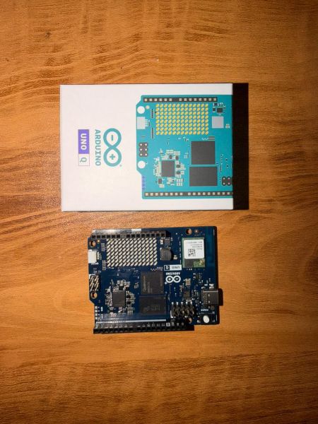
Part 3 - Arduino Q (UNO Q)#
Arduino Q (also referred to as the Arduino UNO Q or UNO R4 WiFi) is a microcontroller development board that combines the simplicity of Arduino with the power of an industrial-grade microprocessor. It features a unique “Dual-Brain” architecture:
- A Microprocessor (MPU): Powered by the Qualcomm® QRB2210 (Quad-core ARM® Cortex®-A53). It runs a full Debian-based Linux OS, allowing for advanced tasks like Edge AI, Python scripting, and robust WiFi management.
- A Microcontroller (MCU): The STM32U585 (ARM® Cortex®-M33). This handles real-time hardware control, precise timing for pins, and the built-in LED matrix.
Unlike traditional Arduino boards, the UNO Q integrates a Linux-capable processor with AI acceleration, making its development workflow closer to embedded Linux systems than microcontroller-only platforms.
🛠 Setting Up Arduino Q (UNO Q)#
For full functionality—especially for WiFi and cloud control—I use Arduino Cloud / App Lab.
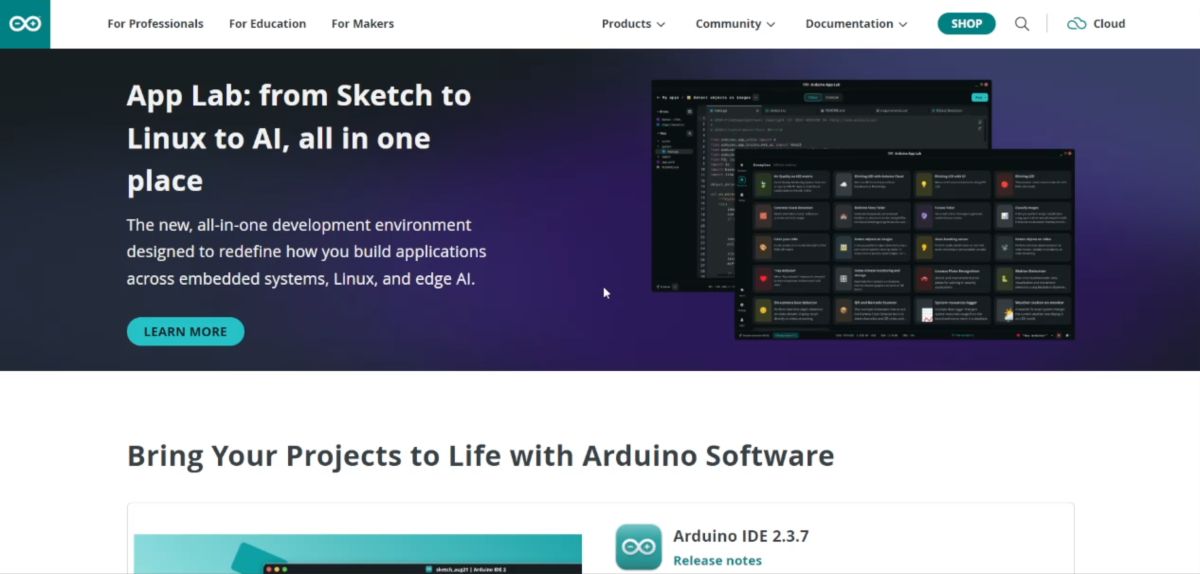
📥 Installation Steps#
- Download: Go to the Arduino Software page and download Arduino App Lab / Arduino Cloud Agent.
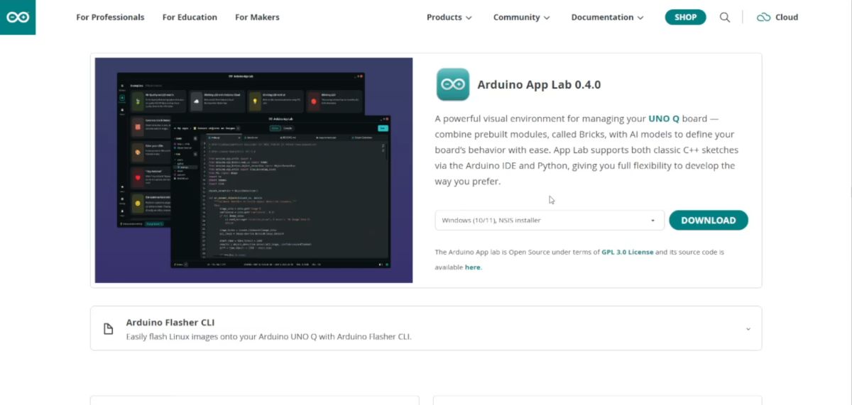
- Open Application: Launch the application on your computer.
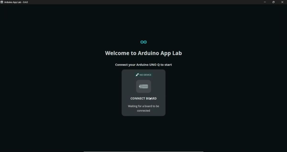
Connect: Plug in the Arduino Q (UNO R4 WiFi) using a USB-C cable.
Auto-Detection: The board should be auto-detected by the software.
Configuration:
- Set Device Name.
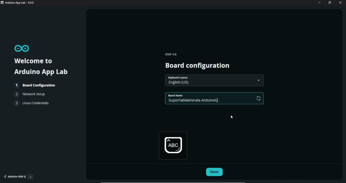
- Enter WiFi SSID and Password.
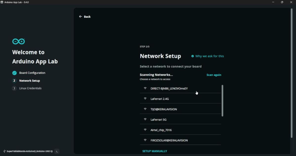
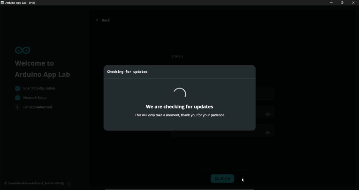
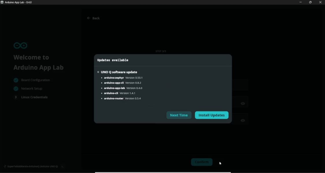
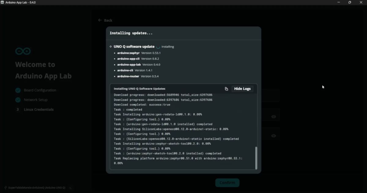
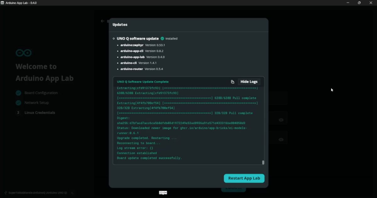
Firmware Update: Check for firmware updates and update if prompted.
Linux Setup: Setup the Linux credentials.
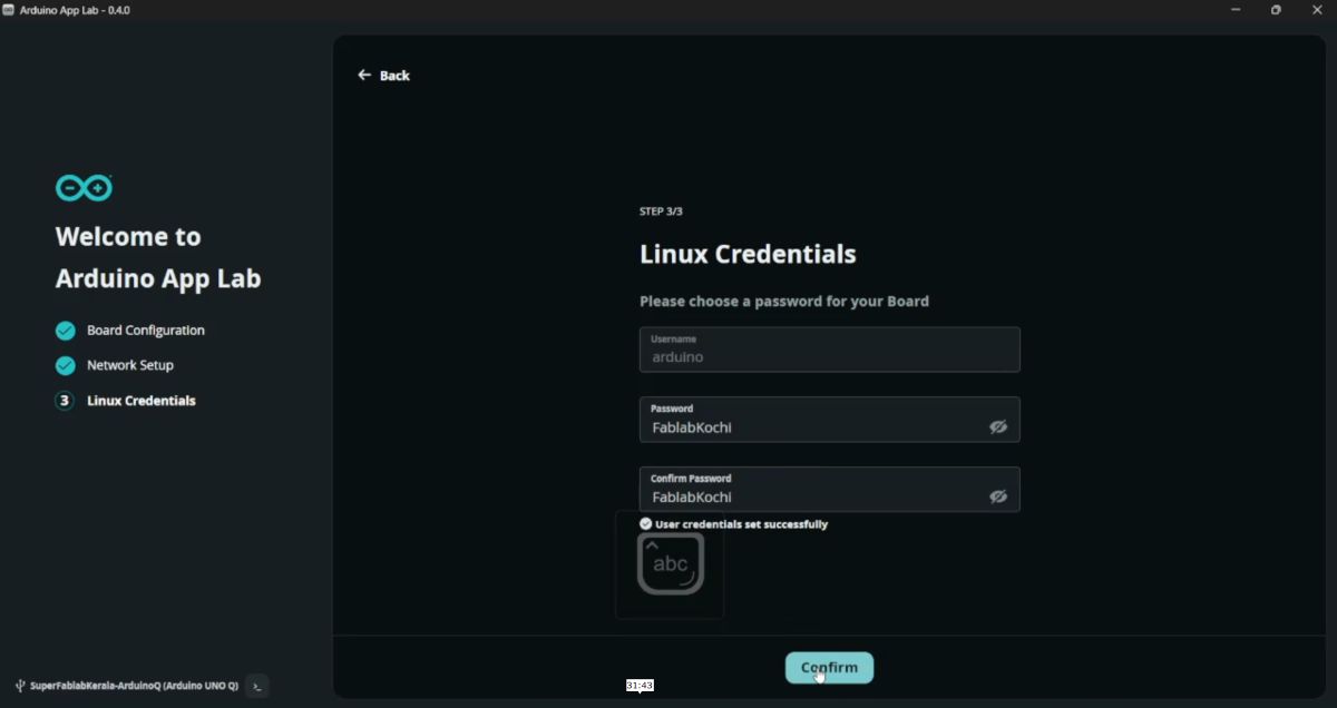
After setup, the board is ready for App Lab based programming.
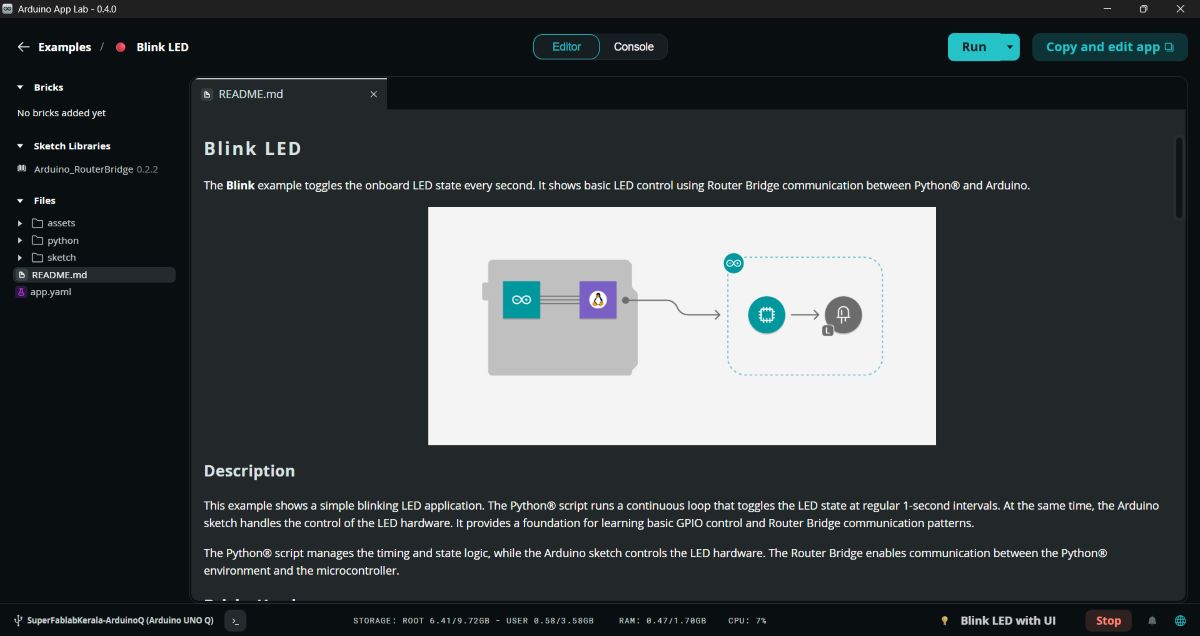
💡 Example 1 — Blink LED with UI#
I tested the cloud functionality by running a basic blink sketch.
Select a built-in Blink example.
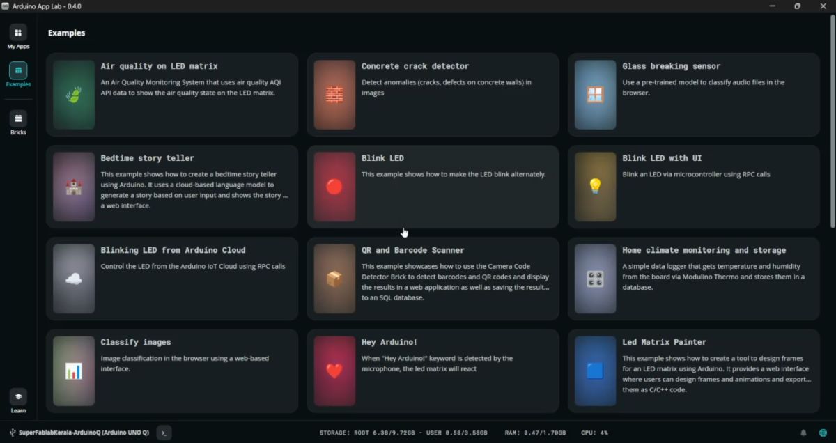
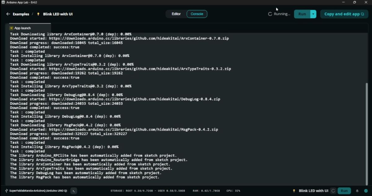
Click Run.
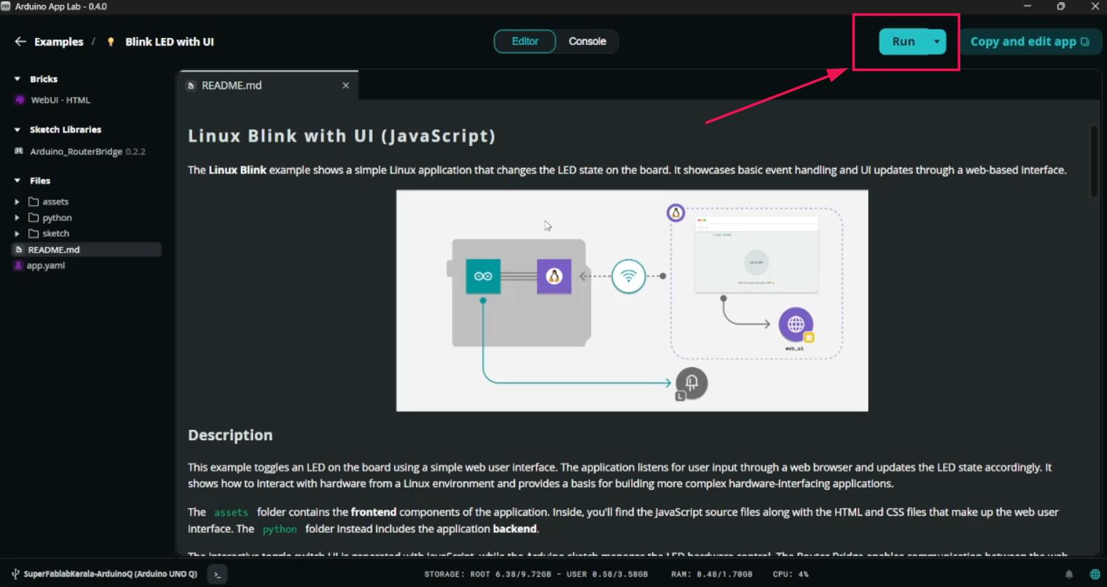
Code compiles automatically.
A webpage opens where the LED can be controlled from the browser.
💻 Arduino IDE Programming#
Even though Cloud is available, the board can also be programmed using the Arduino IDE.
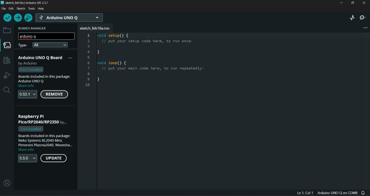
Step 1 — Install Board Package#
Open Board Manager.
Install Arduino UNO Q Boards.
Step 2 — Install Required Libraries#
Install the following libraries to use the display:
#include "ArduinoGraphics.h"#include "Arduino_LED_Matrix.h"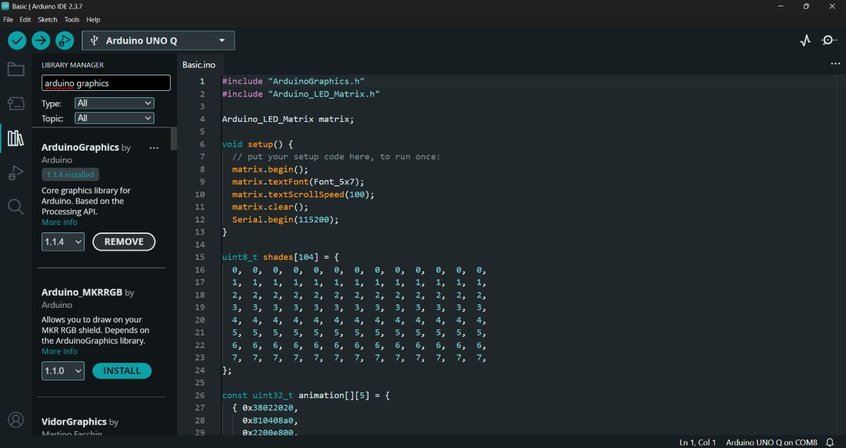
🟢 Example 2 — LED Matrix Animation + Text#
Open the example code and select the Matrix Basic Code.

Code
#include "ArduinoGraphics.h"
#include "Arduino_LED_Matrix.h"

Arduino_LED_Matrix matrix;

void setup() {
  matrix.begin();
  matrix.textFont(Font_5x7);
  matrix.textScrollSpeed(100);
  matrix.clear();
  Serial.begin(115200);
}

uint8_t shades[104] = {
  0,0,0,0,0,0,0,0,0,0,0,0,0,
  1,1,1,1,1,1,1,1,1,1,1,1,1,
  2,2,2,2,2,2,2,2,2,2,2,2,2,
  3,3,3,3,3,3,3,3,3,3,3,3,3,
  4,4,4,4,4,4,4,4,4,4,4,4,4,
  5,5,5,5,5,5,5,5,5,5,5,5,5,
  6,6,6,6,6,6,6,6,6,6,6,6,6,
  7,7,7,7,7,7,7,7,7,7,7,7,7,
};

const uint32_t animation[][5] = {
  {0x38022020,0x810408a0,0x2200e800,0x20000000,66},
  {0x1c011010,0x40820450,0x11007400,0x10000000,66},
  {0x0e008808,0x20410228,0x08803a00,0x08000000,66},
  {0x07004404,0x10208114,0x04401d00,0x04000000,66},
  {0x03802202,0x0810408a,0x02200e80,0x02000000,66},
  {0x01c01101,0x04082045,0x01100740,0x01000000,66},
  {0x00e00880,0x82041022,0x808803a0,0x00000000,66},
  {0x00700440,0x40020011,0x004401c0,0x00000000,66},
  {0x00380200,0x20010008,0x802000e0,0x00000000,66},
  {0x00180100,0x10008004,0x00100060,0x00000000,66},
  {0x00080080,0x08004002,0x00080020,0x00000000,66},
  {0x00000040,0x04002001,0x00040000,0x00000000,66},
  {0x00000000,0x02001000,0x80000000,0x00000000,66},
  {0x00000000,0x00000000,0x00000000,0x00000000,66}
};

void loop() {

  matrix.beginText(0, 0, 127, 0, 0);
  matrix.print("      arduino.cc/uno-q      ");
  matrix.endText(SCROLL_LEFT);

  delay(1000);

  matrix.setGrayscaleBits(3);
  matrix.draw(shades);

  delay(1000);

  matrix.clear();

  matrix.loadSequence(animation);
  for (int i = 0; i < 10; i++) {
    matrix.playSequence();
  }
}
Action: I hit Compile and Upload.
Output: This example demonstrates:
Scrolling text
Custom animation
🧪 Custom LED Matrix Project#
The next thing I tried out was printing on the LED matrix my own Custom Message. Below is the code for that.
Code
#include "ArduinoGraphics.h"
#include "Arduino_LED_Matrix.h"
Arduino_LED_Matrix matrix;

void setup() {
matrix.begin();
matrix.textFont(Font_5x7);
matrix.textScrollSpeed(60);
matrix.clear();
}

void loop() {
matrix.beginText(0, 0, 127, 0, 0);
matrix.print("   SUPERFABLAB KOCHI   FabAcademy 26   ");
matrix.endText(SCROLL_LEFT);

delay(500);
}
Output: The matrix displayed our custom group message.
🔄 Returning to App Lab: Basic Blink (No UI)#
Then I got back to the App Lab and tested another basic blink—the one without any UI.
Action:
- Open Arduino App Lab.

- Select the Basic Blink example (the version without the Cloud/Web Switch).
- Click Run.
Output: The board reset and the LED started blinking immediately.
Running Arduino Q as a Standalone System#
Running Arduino Q as a standalone system and running apps from within instead of using IDE or external PC.
Step 1: Connect Peripherals#
Connect the Arduino Q to a USB hub along with a monitor, keyboard, and mouse.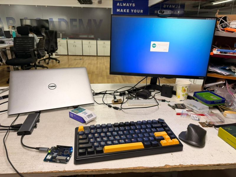
Step 2: Login#
Login to the Arduino Q.
Step 3: Open AppLab#
Open the AppLab.
Step 4: Select QR Code Detection App#
Select the QR code detection app.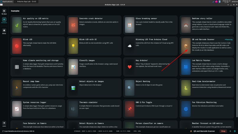
Step 5: Run the App#
Run the application.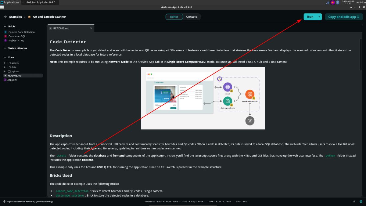
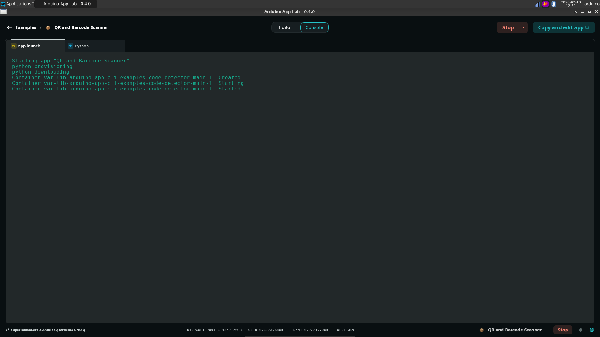
Step 6: Scan QR Code#
Scan the QR code on the browser.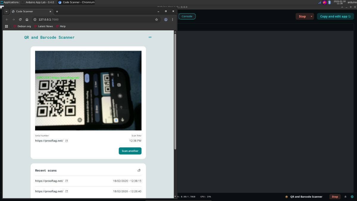
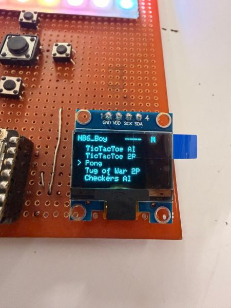
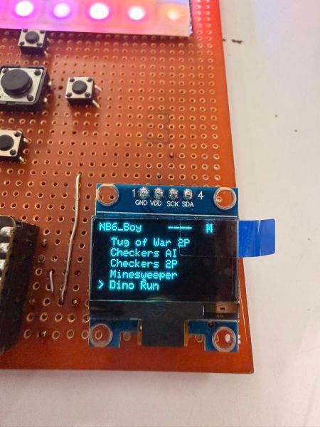
Assembling My Own Embedded System: The ESP32-C6 Game Console#
Part 1: The Origin Story#
It all started out as a joke. I was playing around with a NeoPixel matrix and thought, “What is something fun I could do with this?” I realized the hardware had more than enough capability to run Snake.
I started having a “vibe coding” session with Claude, and guess what? It gave me the code. I connected everything to a breadboard, and I actually got it working!
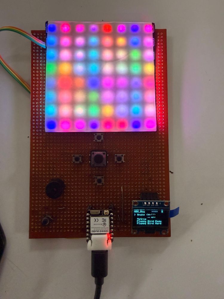
The Hardware#
- Microcontroller: Seeed Studio XIAO ESP32-C6
- Display: NeoPixel Matrix & OLED Display
- Audio: Passive Buzzer
- Connectivity: WiFi
The Game Library#
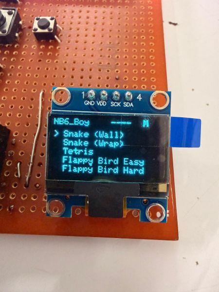
What started as just Snake evolved into a massive library of games:
- Classics: Snake (Wall), Snake (Wrap), Tetris
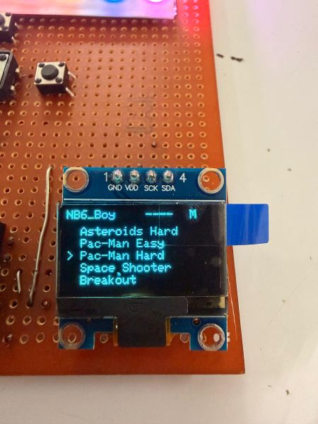
- Arcade: Flappy Bird (Easy & Hard), Asteroids (Hard), Pac-Man (Easy & Hard), Space Shooter, Breakout
- Strategy/Board: TicTacToe (AI & 2P), Checkers (AI & 2P), Minesweeper
- Multiplayer: Pong (Air Hockey), Tug of War (2P)
- Extras: Dino Game
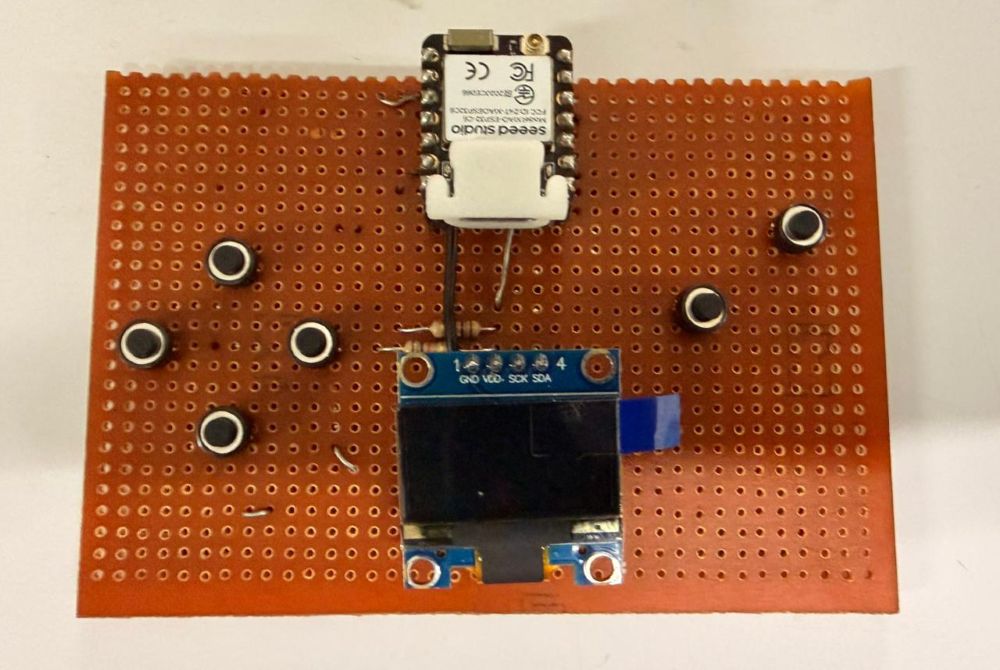
Part 2: From Breadboard to PCB#
That night, I was hanging out at a local makerspace called Tinkerspace .
After handing the breadboard prototype to a few fellow makers and asking what they thought, I got motivated to add more games to it. I realized it needed a permanent body rather than a bunch of stray wires that are prone to disconnect at any moment.
The Build Process#
- Soldering: I soldered up a PCB on a perfboard to make it sturdy.
- Vibe Coding: I got back to coding, adding a buzzer for sound.
- Iterative Design: I added each game one by one.
- Alpha Testing: I handed it over to the makers at Tinkerspace for testing, made revisions based on their feedback, and kept adding games.
- UI Upgrade: I added an OLED display to show the game score and a selection menu.
Part 3: Cloud Integration & High Scores#
Then it got me wondering: Why not push my high scores to my Fab Academy website?
I jumped onto Firebase, set up a Realtime Database, and added the API keys to my GameBoy code so that it can push the latest “Top 3” high scores to my site.
The Logic Flow#
The system manages connectivity intelligently to avoid interrupting gameplay:
- Check for High Score: The system constantly monitors if a new high score has been set.
- Check Connection Mode:
- Connects to my phone’s personal hotspot.
- Push Data: It pushes the score into the Firebase Realtime Database.
- Website Update: My personal website pulls the value from the JSON string in the database and updates the leaderboard automatically.
Full Gameplay#
Qpad Project#
While going through the Fab Academy schedule, I came across the Qpad assignment. I referred to the documentation: https://gitlab.cba.mit.edu/quentinbolsee/qpad-xiao
I built my own Qpad as a separate project using a Raspberry Pi-based setup.
Qpad Gameplay#
prompt used to generate the games:
https://claude.ai/share/b8900a25-de2e-4065-bad0-c78baf9f22c8Reflection#
This week was a shift from just writing code to actually understanding how embedded systems behave in real-world scenarios. I explored different workflows — not just the typical Arduino IDE approach, but also running systems in a more standalone way (like using Arduino Q with Linux and AppLab). This gave me a broader perspective on how embedded devices can function independently without relying on a host PC.
A major takeaway was how important the interaction between hardware and software is. Even simple tasks required careful handling of connections, pin configurations, and dependencies. I faced multiple issues while compiling and running programs, which forced me to debug systematically rather than randomly trying fixes. This improved my problem-solving approach significantly.
I also realized that there is no single “correct” workflow in embedded programming — different boards (RP2040, ESP32, etc.) and environments offer different advantages, and choosing the right one depends on the use case.
Overall, this week made me more confident in experimenting with embedded systems, trying out unconventional setups, and thinking beyond basic examples towards building complete, standalone systems.