Week 11 - Networking and Communications#
Week 11 was all about networking and communications — actually getting devices to talk to each other, not just in theory but in a way where something physical happens at the other end.
The individual assignment was to design, build, and connect wired or wireless nodes with network or bus addresses and local input/output. I took that as a chance to build something I’d actually use: a wireless QWERTY keyboard system where you type on a physical device and the text appears on your PC.
This week built directly on the board I made in Week 8. The custom PCB already has 6 push buttons and an OLED header onboard, so I didn’t need to wire anything extra on the ESP32 side. The other node is a bare Raspberry Pi Pico W connected to my PC via USB — no custom board, just the chip itself.
Group Assignment#
- Send a message between two projects
Individual Assignment#
- Design, build, and connect wired or wireless node(s) with network or bus addresses and local input &/or output device(s)
Extra Credit Goals:
- Try multiple communication protocols (I2C, SPI, UART, Wi-Fi, Bluetooth, etc.)
- Implement a network of more than two nodes
What I Learned#
- WiFi AP mode vs STA mode — and why AP made way more sense here (portability, no router dependency, the two devices just form their own network)
- UDP vs TCP for short bursts: no handshake, no connection state, lower overhead. If a packet drops, you just hit SEND again. Simple.
- The Pico W can act as a USB HID keyboard to your PC with zero driver setup — the OS literally just sees it as a keyboard
- The ESP32-C6 can’t do USB HID at all. It only has USB Serial/JTAG hardware, no OTG. This is why the Pico W exists in this setup.
- Debounce and multi-gesture detection (single tap, double tap, long press) without any
delay()— all done withmillis()timers - Serving HTML from an ESP32 with no filesystem — you store the page in
PROGMEMso it lives in flash instead of eating your RAM - I2C at a practical level: two wires (SDA + SCL), main picks the secondary by address, the library handles all the framing. You just call
display.display().
Software Used#
- Arduino IDE — firmware for both boards
- Serial Monitor — debugging WiFi connection and UDP packet flow on the Pico W
- Browser — testing the web UI served by the ESP32-C6
Weekly Schedule#
| Day | What I Did |
|---|---|
| WED | Lecture on networking and communications |
| THU | Planned the two-node architecture, decided on WiFi UDP + USB HID approach |
| FRI | Wrote and tested ESP32-C6 firmware — WiFi AP, web server, OLED keyboard UI |
| SAT | Wrote and tested Pico W firmware — WiFi client, UDP listener, USB HID output |
| SUN | Integration testing — full end-to-end text from OLED keyboard to PC |
| MON | Web UI polish, documentation writeup |
| TUE | Regional review |
Individual Assignment#
Wireless QWERTY Keyboard System#
XIAO ESP32-C6 (custom Week 8 PCB) + Raspberry Pi Pico W#
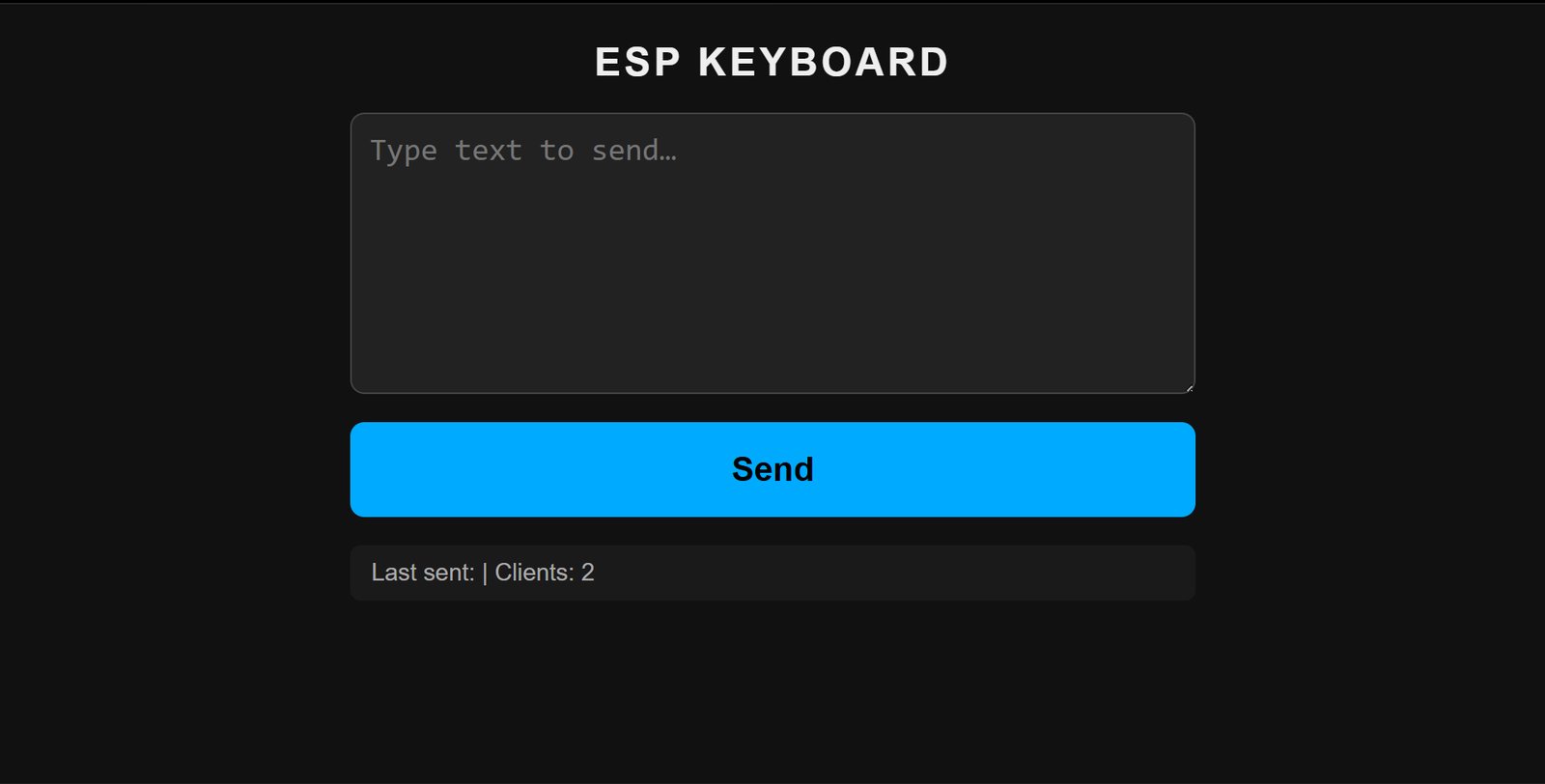
A two-device wireless text input system. You type on a physical QWERTY keyboard rendered on an OLED display (or via a web browser), and the text gets wirelessly transmitted to a Raspberry Pi Pico W which types it on your PC as if it were a real USB keyboard.
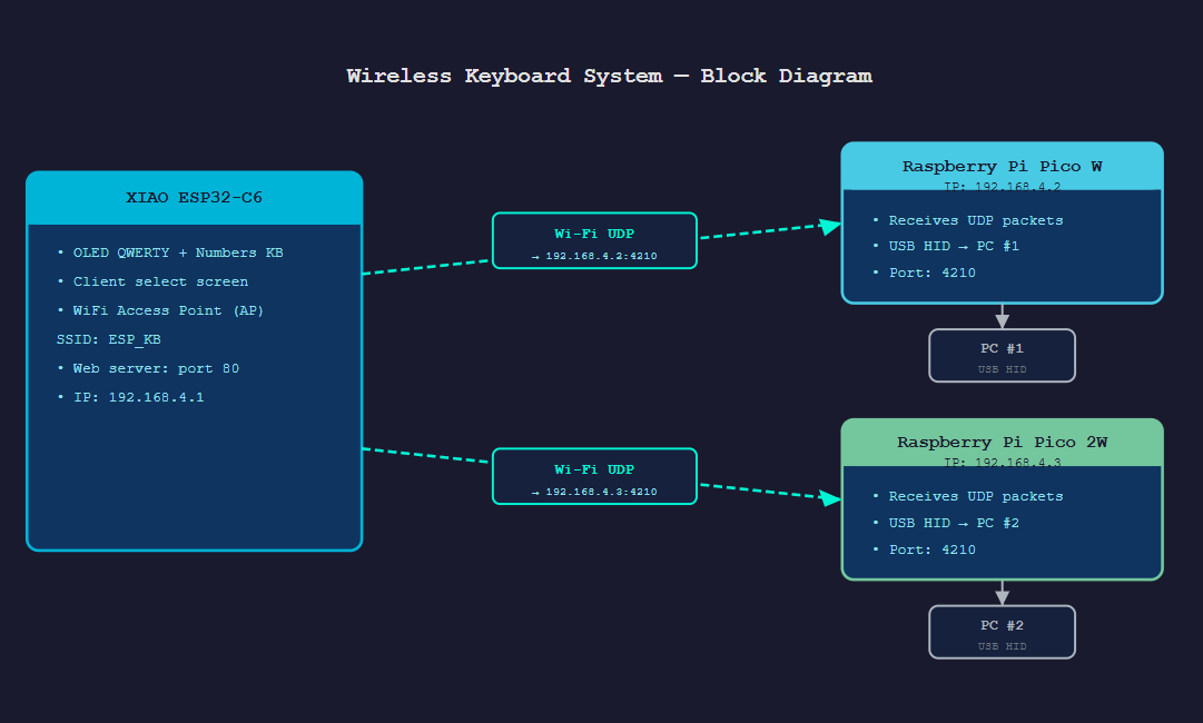
How it works — big picture#
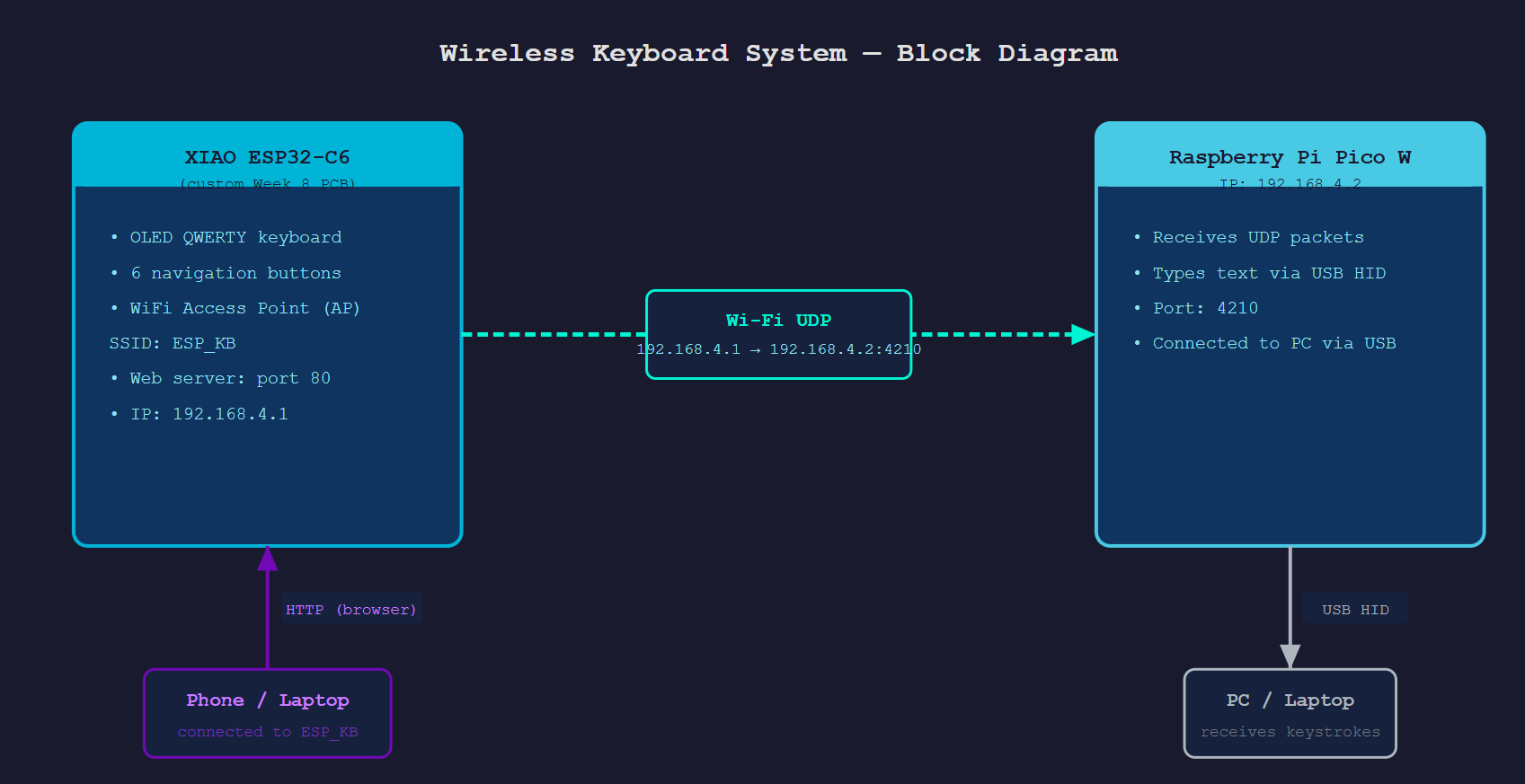
AI PROMPT USED: “Make me a clean block diagram for a two-device wireless keyboard system. Box 1 is a XIAO ESP32-C6 on a custom PCB — show it running an OLED QWERTY keyboard, 6 navigation buttons, a WiFi Access Point named ESP_KB on IP 192.168.4.1, and a web server on port 80. Box 2 is a Raspberry Pi Pico W on IP 192.168.4.2 — show it receiving UDP packets on port 4210 and typing text via USB HID. Connect the two boxes with a dashed arrow labelled ‘Wi-Fi UDP, 192.168.4.1 → 192.168.4.2:4210’. Add a third box for a phone/laptop connecting to the ESP32 over HTTP, and a fourth box for the PC that receives the keystrokes over USB HID. Dark background, monospace font, cyan/purple accent colors.”
Hardware#
Device 1 — Custom Week 8 PCB (XIAO ESP32-C6)#
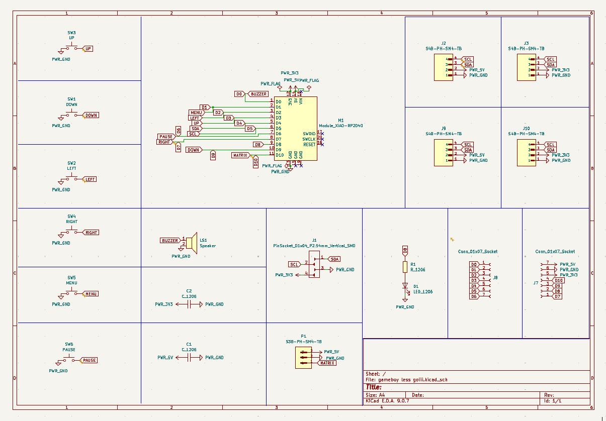
This is the custom PCB I designed in Week 6 — Electronics Design and milled/soldered in Week 8 — Electronics Production . The XIAO ESP32-C6 is soldered directly onto it, and all 6 buttons plus the I2C header are already wired up — no breadboarding needed on this side.
Here’s the schematic for the board, straight from the Week 6 KiCad design, so the wiring is clear at a glance:
| Component | Role |
|---|---|
| Seeed XIAO ESP32-C6 | Main MCU — runs WiFi AP, web server, OLED UI |
| SSD1306 OLED 128×64 | Connected via the I2C header (J1) on the PCB |
| 6× push buttons (onboard) | Navigation (UP/DOWN/LEFT/RIGHT/SPACE/SEND) |
OLED wiring (I2C header on PCB)#
The OLED plugs into the 4-pin I2C header (J1) already broken out on the Week 8 board:
| OLED Pin | PCB Header Pin |
|---|---|
| VCC | 3V3 |
| GND | GND |
| SDA | SDA (D4) |
| SCL | SCL (D5) |
The 6 navigation buttons are already soldered to the PCB — no extra wiring needed.
Device 2 — Raspberry Pi Pico W (bare board, no custom PCB)#
Just a bare Pico W. No custom board, no extra components. The USB cable powers it and is also what makes it look like a keyboard to the PC.
This is an off-the-shelf board straight from Raspberry Pi — there’s no design or production week for it on this site since I didn’t make a custom PCB for it.
| Component | Role |
|---|---|
| Raspberry Pi Pico W | Connects to ESP_KB WiFi, listens for UDP, types via USB |
| USB cable | Powers the Pico W and presents it as a USB keyboard to the PC |
Protocols used#
1. I2C (Inter-Integrated Circuit)#
I2C is how the ESP32-C6 talks to the OLED. Two wires: SDA (data) and SCL (clock). The ESP32 is the main, the SSD1306 is the secondary at address 0x3C. Every time you update the display, it ships the entire 128×64 pixel buffer (1024 bytes) over those two wires. The Adafruit SSD1306 library handles all the framing — you just call display.display().
Why I2C and not SPI? The SSD1306 supports both, but the 4-pin OLED modules almost always use I2C since it only needs 2 signal wires. Plus the Week 8 PCB already has the I2C header broken out, so it was the obvious choice.
Clock speed is 100kHz by default (standard mode), but the library can push to 400kHz.
Uploaded to: XIAO ESP32-C6 (custom Week 8 PCB) only — the OLED only exists on this board.
Code responsible for this:
// esp32_keyboard.ino
#define OLED_SDA  D4
#define OLED_SCL  D5
...
Wire.begin(OLED_SDA, OLED_SCL);
if (!display.begin(SSD1306_SWITCHCAPVCC, OLED_ADDR)) { ... }
...
display.display();   // ships the whole 1024-byte frame buffer over I2C
Wire.begin() sets up the two I2C pins, display.begin() does the handshake with the SSD1306 at address 0x3C, and every display.display() call is the actual I2C transaction that pushes the frame buffer out.
2. WiFi 802.11 (Access Point mode)#
The ESP32-C6 runs as a WiFi Access Point — it broadcasts its own network instead of connecting to your home router:
SSID     : ESP_KB
Password : 12345678
AP IP    : 192.168.4.1
Any device that joins ESP_KB gets an IP in the 192.168.4.x range. The Pico W uses a static IP of 192.168.4.2 so the ESP32 always knows where to send UDP packets.
The ESP32-C6 also supports simultaneous STA (Station) mode — you can have it connect to your home router at the same time. Set STA_SSID and STA_PASS in the code to enable it.
Why AP mode? Portability. The system works anywhere without needing an existing network. Plug in the two boards and you’re good.
Uploaded to: XIAO ESP32-C6 (custom Week 8 PCB) — this is the device that hosts the network. The Picos just join it as clients.
Code responsible for this:
// esp32_keyboard.ino
void setupWiFiAP() {
  WiFi.mode(WIFI_AP_STA);
  WiFi.softAP(AP_SSID, AP_PASS);
  Serial.print("[WiFi] AP started — IP: ");
  Serial.println(WiFi.softAPIP());

  if (strlen(STA_SSID) > 0) {
    WiFi.begin(STA_SSID, STA_PASS);   // optional simultaneous home-router connection
  }
}
WiFi.softAP() is the one line that actually turns the ESP32-C6 into its own access point. WIFI_AP_STA mode means it can also join a home router on the side, but that part only fires if STA_SSID isn’t left blank.
Where the addressing lives: the Pico W and Pico 2W don’t search for the ESP32 — they’re each hard-coded with a fixed IP inside their own #define STATIC_IP (see the UDP section below for exactly where that’s edited).
3. UDP (User Datagram Protocol)#
UDP is how the ESP32 sends text to the Pico W. When you press SEND on the OLED or hit submit on the web UI, the ESP32 fires off a UDP packet:
Source      : 192.168.4.1 (ESP32-C6 AP IP)
Destination : 192.168.4.2:4210 (Pico W static IP, port 4210)
Payload     : raw UTF-8 text + '\n' terminator
Max size    : 200 characters + newline
The Pico W keeps a socket open on port 4210 and checks udp.parsePacket() every loop (non-blocking). When something arrives, it reads the bytes and starts typing.
Why UDP and not TCP? For short text bursts, UDP is way simpler — no handshake, no connection state to maintain, no retransmit overhead. If a packet gets lost, just press SEND again. The latency is lower too since there’s no TCP acknowledgement round-trip.
Uploaded to: both sides — the ESP32-C6 sends, the Pico W and Pico 2W receive.
Code responsible for this — sending side (ESP32-C6):
// esp32_keyboard.ino
void sendUDP(const char* text, int len, const char* destIP) {
  IPAddress dest;
  dest.fromString(destIP);
  udp.beginPacket(dest, PICO_PORT);
  udp.write((const uint8_t*)text, len);
  udp.write((const uint8_t*)"\n", 1);
  udp.endPacket();
}
Code responsible for this — receiving side (Pico W / Pico 2W):
// pico_hid.ino  /  pico2w_hid.ino
int packetSize = udp.parsePacket();
if (packetSize > 0) {
  int len = udp.read(packetBuf, sizeof(packetBuf) - 1);
  packetBuf[len] = '\0';
  blinkLED();
  typeText(packetBuf, len);
}
Where the board addressing is edited:
Each Pico is given a fixed IP with one #define near the top of its own file:
// pico_hid.ino   (Raspberry Pi Pico W)
#define STATIC_IP   "192.168.4.2"
#define GATEWAY     "192.168.4.1"
// pico2w_hid.ino (Raspberry Pi Pico 2W)
#define STATIC_IP "192.168.4.3" // only line that's different from pico_hid.ino
#define GATEWAY "192.168.4.1"That STATIC_IP gets applied in connectWiFi() via WiFi.config(ip, gw, sn) before WiFi.begin() is called, so each Pico claims the same address on every boot instead of getting a random one from DHCP.
The ESP32-C6 firmware has to agree with both of those addresses, so it carries matching #defines of its own:
// esp32_keyboard.ino
#define PICO_IP    "192.168.4.2"   // must match STATIC_IP in pico_hid.ino
#define PICO2_IP   "192.168.4.3"   // must match STATIC_IP in pico2w_hid.ino
#define PICO_PORT  4210
If I ever change a Pico’s STATIC_IP, I have to change the matching PICO_IP/PICO2_IP line in esp32_keyboard.ino too, otherwise the ESP32 just keeps firing UDP packets at an address nothing is listening on.
4. HTTP (HyperText Transfer Protocol)#
The ESP32-C6 runs a minimal HTTP/1.1 web server on port 80 with three endpoints:
GET /#
Returns the full web UI page. The HTML is stored in flash memory (PROGMEM) as a raw string — this keeps it from eating into RAM on boot. The page has a <textarea>, a Send button, and a status line that auto-refreshes.
POST /send#
The browser posts typed text here as application/x-www-form-urlencoded:
msg=Hello+WorldThe ESP32 decodes it, forwards it via UDP to the Pico W, and returns 200 OK.
GET /status#
Returns a small JSON blob:
{"last_sent": "Hello World", "clients": 1}The web page polls this every 2 seconds using fetch() and updates the status line without reloading.
Why store HTML in PROGMEM? No filesystem on this board, so the HTML gets compiled directly into flash. Without PROGMEM it would get copied into RAM on boot, which the ESP32-C6 does not have a lot of.
Uploaded to: XIAO ESP32-C6 (custom Week 8 PCB) — the web server only runs there.
Code responsible for this:
// esp32_keyboard.ino
server.on("/", HTTP_GET, []() {
  server.send_P(200, "text/html", HTML_PAGE);
});

server.on("/send", HTTP_POST, []() {
  String msg = server.arg("msg");
  int clientIdx = server.hasArg("client") ? server.arg("client").toInt() : 0;
  const char* destIP = (clientIdx == 0) ? PICO_IP : PICO2_IP;
  sendUDP(msg.c_str(), msg.length(), destIP);
  server.send(200, "text/plain", "OK");
});

server.on("/status", HTTP_GET, []() {
  String json = "{\"last_sent\":\"" + String(lastSent) + "\",\"clients\":" + WiFi.softAPgetStationNum() + "}";
  server.send(200, "application/json", json);
});
server.on() is what wires up each route. / just hands back the page baked into flash, /send is where the HTTP request actually turns into a UDP packet (it reuses the same sendUDP() from the UDP section above), and /status is what the page polls every 2 seconds to update the little status line without a full reload.
5. USB HID (Human Interface Device)#
This is the part I found genuinely cool. The Pico W tells the PC it’s a USB keyboard using the TinyUSB stack (built into the Earle Philhower arduino-pico core). The PC just sees another keyboard — no drivers, no setup.
When a UDP packet arrives, the Pico W loops through each character and calls Keyboard.write(c) with a 20ms delay between characters. TinyUSB handles all the USB descriptor negotiation and HID report formatting internally.
Under the hood, HID key reports are 8-byte USB packets:
- Modifier byte (Shift, Ctrl, Alt, etc.)
- Reserved byte
- 6 keycodes (up to 6 simultaneous keys)
Keyboard.write() automatically handles uppercase by setting the Shift modifier — you don’t deal with that manually.
Why the Pico W and not the ESP32-C6 for this? The ESP32-C6 has no USB OTG hardware — it can only do USB Serial/JTAG (basically just programming and debug). The Pico W’s RP2040 has a full USB controller that supports device mode, so it can actually act as a keyboard.
Uploaded to: Raspberry Pi Pico W and Raspberry Pi Pico 2W — this is the one protocol the ESP32-C6 has no part in at all.
Code responsible for this:
// pico_hid.ino  /  pico2w_hid.ino
#include <Keyboard.h>

void setup() {
  Keyboard.begin();   // tells the host PC "I'm a USB keyboard now"
  ...
}

void typeText(const char* text, int len) {
  if (text[len - 1] == '\n') len--;        // strip the sender's terminator
  for (int i = 0; i < len; i++) {
    char c = text[i];
    if ((c >= 32 && c <= 126) || c == '\n' || c == '\t') {
      Keyboard.write(c);                    // sends the HID key-down + key-up report
      delay(CHAR_DELAY_MS);                 // 20 ms gap so the OS doesn't drop keystrokes
    }
  }
}
Keyboard.begin() is what makes the TinyUSB stack present the board to the host as an HID keyboard in the first place. typeText() is called straight out of the UDP receive handler — as soon as a packet lands, this function is what actually types it out, one Keyboard.write() per character.
Software architecture#
AI PROMPT USED: “Write Arduino firmware for a XIAO ESP32-C6 that runs an OLED QWERTY keyboard. It needs to read 6 debounced push buttons with no
delay()in the loop, support single-press/double-press/long-press gestures, run a WiFi Access Point called ESP_KB, serve a simple HTML page with a textarea and Send button stored in PROGMEM, send the typed text over UDP to a fixed Pico W IP on port 4210, and expose a /status JSON endpoint. Then write a matching sketch for a Raspberry Pi Pico W using the arduino-pico core that connects to that same AP with a static IP, listens for those UDP packets, and types the received text out as a USB HID keyboard using Keyboard.write(), with a small delay between characters so the host doesn’t drop keystrokes. Keep all the network settings as #define constants at the top of each file so they’re easy to change later.”
ESP32-C6 firmware (esp32_keyboard.ino)#
State machine — 3 screens#
The OLED cycles through 3 screens with a long-press of SEND (≥1 second):
Button input system#
All 6 buttons on the Week 8 PCB use INPUT_PULLUP (active LOW). The firmware reads each button every loop and applies a 50ms debounce — a state change only registers after the pin has been stable for 50ms. This stops a single press from registering as multiple.
Three timing-based gestures, all using millis() with no delay():
| Gesture | Button | Window | Action |
|---|---|---|---|
| Single press | SPACE | — | Select key under cursor |
| Double press | SPACE | 300ms | Insert literal space |
| Long press | SEND | 1000ms | Cycle to next screen |
| Short press | SEND | <1000ms | Send text buffer via UDP |
Double-press detection logic:
On SPACE press:
  If a previous tap was within 300ms → double tap → insert space
  Else → start 300ms timer, wait for second tap

Every loop:
  If timer expired and no second tap → single tap → select key
OLED rendering (screen 0 — QWERTY)#
The 128×64 display is divided into zones:
Y=0  ┌────────────────────────────────┐
     │ Q W E R T Y U I O P      CAP  │  ← Row 0 (10 keys, 12px/key)
Y=10 │  A S D F G H J K L            │  ← Row 1 (9 keys, offset 10px)
Y=20 │    Z X C V B N M              │  ← Row 2 (7 keys, offset 22px)
Y=30 │  [CAP]  [BKS]   [SND]         │  ← Row 3 (special keys)
Y=39 ├────────────────────────────────┤  ← separator line
Y=42 │ current text buffer (21 chars) │  ← scrolling text
Y=56 │ Len:12                         │  ← char count / status
     └────────────────────────────────┘
The selected key is highlighted by drawing a filled white rectangle and rendering the letter in black (inverted). The display only redraws when a displayDirty flag is set — no point hammering I2C every loop if nothing changed.
Full code — esp32_keyboard.ino#
#include <Wire.h>
#include <Adafruit_GFX.h>
#include <Adafruit_SSD1306.h>
#include <WiFi.h>
#include <WebServer.h>
#include <WiFiUDP.h>

// ─── Pin Definitions ─────────────────────────────────────────
#define BTN_UP    D3
#define BTN_DOWN  D9
#define BTN_LEFT  D2
#define BTN_RIGHT D7
#define BTN_SPACE D6
#define BTN_SEND  D1
#define OLED_SDA  D4
#define OLED_SCL  D5

// ─── Network Configuration ───────────────────────────────────
#define AP_SSID   "ESP_KB"
#define AP_PASS   "12345678"
#define STA_SSID  ""
#define STA_PASS  ""

#define PICO_IP    "192.168.4.2"   // Pico W
#define PICO2_IP   "192.168.4.3"   // Pico 2W
#define PICO_PORT  4210

// ─── OLED ────────────────────────────────────────────────────
#define SCREEN_W  128
#define SCREEN_H  64
#define OLED_ADDR 0x3C
Adafruit_SSD1306 display(SCREEN_W, SCREEN_H, &Wire, -1);

// ─── Web Server & UDP ────────────────────────────────────────
WebServer server(80);
WiFiUDP   udp;

// ─── Button indices ───────────────────────────────────────────
#define BTN_IDX_UP    0
#define BTN_IDX_DOWN  1
#define BTN_IDX_LEFT  2
#define BTN_IDX_RIGHT 3
#define BTN_IDX_SPACE 4
#define BTN_IDX_SEND  5
#define NUM_BTNS      6

const uint8_t BTN_PINS[NUM_BTNS] = {
  BTN_UP, BTN_DOWN, BTN_LEFT, BTN_RIGHT, BTN_SPACE, BTN_SEND
};

struct BtnState {
  bool      lastRaw;
  bool      pressEvent;
  bool      releaseEvent;
  bool      isHeld;
  unsigned long debounceTime;
  unsigned long pressTime;
};
BtnState btns[NUM_BTNS];

#define DEBOUNCE_MS 50

// ─── Keyboard Layout ─────────────────────────────────────────
// 5 rows: numbers, QWERTY, ASDF, ZXC, special
#define KEY_CAPS  '\x01'
#define KEY_BKSP  '\x02'
#define KEY_SEND  '\x03'

#define KB_NUM_ROWS 5

const char* KB_ROWS[KB_NUM_ROWS] = {
  "1234567890",    // row 0
  "QWERTYUIOP",   // row 1
  "ASDFGHJKL",    // row 2
  "ZXCVBNM",      // row 3
  "\x01\x02\x03"  // row 4: CAPS, BKSP, SEND
};
const int KB_ROW_LEN[KB_NUM_ROWS]   = {10, 10, 9, 7, 3};
// X offset so each row appears centred
const int KB_ROW_OFF_X[KB_NUM_ROWS] = {4, 4, 10, 22, 8};
// Y pixel top of each row — 8px per row to fit all 5 in ~40px
const int KB_ROW_Y[KB_NUM_ROWS]     = {0, 8, 16, 24, 32};

#define KEY_CELL_W   12
const int SPECIAL_W[3] = {30, 36, 40};  // CAP, BKS, SND

// ─── Keyboard cursor state ───────────────────────────────────
int  curRow = 1;   // default to QWERTY row (row 1)
int  curCol = 0;
bool capsOn  = false;

// ─── Text buffer ─────────────────────────────────────────────
#define TEXT_BUF_MAX 200
char textBuf[TEXT_BUF_MAX + 1];
int  textLen = 0;

// ─── Screen state ────────────────────────────────────────────
enum Screen {
  SCR_KEYBOARD      = 0,
  SCR_CLIENT_SELECT = 1,   // shown after short-press SEND on keyboard
  SCR_STATUS        = 2
};
Screen currentScreen = SCR_KEYBOARD;
bool   displayDirty  = true;

// ─── Client selection ────────────────────────────────────────
// 0 = Pico W (192.168.4.2), 1 = Pico 2W (192.168.4.3)
int selectedClient = 0;

// ─── Last sent string (for status display) ──────────────────
char lastSent[64] = "";

// ─── Double-press detection for SPACE ───────────────────────
unsigned long spaceFirstTap = 0;
bool          spaceWaiting  = false;
#define DOUBLE_TAP_WINDOW_MS 300

// ─── Long-press detection for SEND ──────────────────────────
bool sendLongFired = false;

// ─── Inline HTML page ────────────────────────────────────────
static const char HTML_PAGE[] PROGMEM = R"rawhtml(
<!DOCTYPE html>
<html lang="en">
<head>
<meta charset="utf-8">
<meta name="viewport" content="width=device-width, initial-scale=1">
<title>ESP Keyboard</title>
<style>
  *{box-sizing:border-box;margin:0;padding:0}
  body{font-family:sans-serif;background:#111;color:#eee;display:flex;
       flex-direction:column;align-items:center;padding:20px;gap:16px}
  h1{font-size:1.4rem;letter-spacing:2px}
  textarea{width:100%;max-width:480px;height:160px;font-size:1.1rem;
           padding:10px;border-radius:8px;border:1px solid #444;
           background:#222;color:#fff;resize:vertical}
  .client-row{width:100%;max-width:480px;display:flex;gap:12px}
  .client-btn{flex:1;padding:12px;font-size:1rem;border:2px solid #444;
              border-radius:8px;background:#222;color:#aaa;cursor:pointer;
              text-align:center;transition:all .15s}
  .client-btn.active{border-color:#0af;color:#0af;background:#0a1a22}
  button{width:100%;max-width:480px;padding:16px;font-size:1.2rem;
         background:#0af;border:none;border-radius:8px;color:#000;
         font-weight:bold;cursor:pointer}
  button:active{background:#08c}
  #status{width:100%;max-width:480px;font-size:.85rem;color:#aaa;
          background:#1a1a1a;padding:8px 12px;border-radius:6px;
          word-break:break-all}
</style>
</head>
<body>
<h1>ESP KEYBOARD</h1>
<textarea id="msg" placeholder="Type text to send…"></textarea>
<div class="client-row">
  <div class="client-btn active" id="cb0" onclick="selectClient(0)">Pico W<br><small>192.168.4.2</small></div>
  <div class="client-btn"        id="cb1" onclick="selectClient(1)">Pico 2W<br><small>192.168.4.3</small></div>
</div>
<button onclick="sendText()">Send</button>
<div id="status">Waiting for status…</div>

<script>
var activeClient=0;
function selectClient(n){
  activeClient=n;
  document.getElementById('cb0').className='client-btn'+(n===0?' active':'');
  document.getElementById('cb1').className='client-btn'+(n===1?' active':'');
}
function sendText(){
  const msg=document.getElementById('msg').value;
  if(!msg)return;
  fetch('/send',{method:'POST',headers:{'Content-Type':'application/x-www-form-urlencoded'},
        body:'msg='+encodeURIComponent(msg)+'&client='+activeClient})
    .then(r=>r.text())
    .then(()=>{document.getElementById('msg').value='';fetchStatus();})
    .catch(e=>console.error(e));
}
function fetchStatus(){
  fetch('/status').then(r=>r.json()).then(d=>{
    document.getElementById('status').textContent=
      'Last sent: '+d.last_sent+' | Clients: '+d.clients;
  }).catch(()=>{});
}
setInterval(fetchStatus,2000);
fetchStatus();
</script>
</body>
</html>
)rawhtml";

// ─── Forward declarations ────────────────────────────────────
void readButtons();
bool btnJustPressed(int idx);
bool btnJustReleased(int idx);
bool btnHeld(int idx, unsigned long ms);

void handleSpaceButton();
void handleSendButton();
void handleNavButtons();

void selectCurrentKey();
void appendChar(char c);
void doBackspace();
void sendText(int clientIdx);
void toggleCaps();
void openClientSelect();

void drawScreen();
void drawKeyboardScreen();
void drawClientSelectScreen();
void drawStatusScreen();
void drawKeyRow(int row);
int  specialKeyX(int col);

void setupWiFiAP();
void setupWebServer();
void sendUDP(const char* text, int len, const char* destIP);

// ─────────────────────────────────────────────────────────────
void setup() {
  Serial.begin(115200);

  Wire.begin(OLED_SDA, OLED_SCL);
  if (!display.begin(SSD1306_SWITCHCAPVCC, OLED_ADDR)) {
    Serial.println("[OLED] Init failed");
    for (;;) delay(100);
  }
  display.ssd1306_command(SSD1306_SETCONTRAST);
  display.ssd1306_command(0xFF);
  display.clearDisplay();
  display.setTextSize(1);
  display.setTextColor(SSD1306_WHITE);
  display.setCursor(20, 20);
  display.println("ESP Keyboard");
  display.setCursor(20, 32);
  display.println("Starting…");
  display.display();

  for (int i = 0; i < NUM_BTNS; i++) {
    pinMode(BTN_PINS[i], INPUT_PULLUP);
    btns[i] = {false, false, false, false, 0, 0};
  }

  memset(textBuf, 0, sizeof(textBuf));

  setupWiFiAP();
  setupWebServer();
  udp.begin(4211);

  displayDirty = true;
  Serial.println("[SYS] Setup complete");
}

// ─────────────────────────────────────────────────────────────
void loop() {
  readButtons();
  handleSpaceButton();
  handleSendButton();
  handleNavButtons();
  server.handleClient();

  if (displayDirty) {
    drawScreen();
    displayDirty = false;
  }
}

// ─── Button debounce & edge detection ───────────────────────
void readButtons() {
  unsigned long now = millis();
  for (int i = 0; i < NUM_BTNS; i++) {
    bool raw = (digitalRead(BTN_PINS[i]) == LOW);

    if (raw != btns[i].lastRaw) {
      btns[i].debounceTime = now;
      btns[i].lastRaw      = raw;
    }

    if ((now - btns[i].debounceTime) >= DEBOUNCE_MS) {
      bool wasHeld = btns[i].isHeld;
      btns[i].isHeld = raw;

      if (raw && !wasHeld) {
        btns[i].pressEvent   = true;
        btns[i].releaseEvent = false;
        btns[i].pressTime    = now;
      } else if (!raw && wasHeld) {
        btns[i].releaseEvent = true;
        btns[i].pressEvent   = false;
      } else {
        btns[i].pressEvent   = false;
        btns[i].releaseEvent = false;
      }
    } else {
      btns[i].pressEvent   = false;
      btns[i].releaseEvent = false;
    }
  }
}

bool btnJustPressed(int idx)  { return btns[idx].pressEvent; }
bool btnJustReleased(int idx) { return btns[idx].releaseEvent; }
bool btnHeld(int idx, unsigned long ms) {
  return btns[idx].isHeld && (millis() - btns[idx].pressTime >= ms);
}

// ─── SPACE: double-press on keyboard / confirm on client select ──
void handleSpaceButton() {
  if (currentScreen == SCR_CLIENT_SELECT) {
    if (btnJustPressed(BTN_IDX_SPACE)) {
      sendText(selectedClient);
      currentScreen = SCR_KEYBOARD;
      displayDirty  = true;
    }
    return;
  }

  if (currentScreen != SCR_KEYBOARD) return;

  unsigned long now = millis();

  if (btnJustPressed(BTN_IDX_SPACE)) {
    if (spaceWaiting && (now - spaceFirstTap < DOUBLE_TAP_WINDOW_MS)) {
      appendChar(' ');
      spaceWaiting = false;
      displayDirty = true;
    } else {
      spaceWaiting  = true;
      spaceFirstTap = now;
    }
  }

  if (spaceWaiting && (now - spaceFirstTap >= DOUBLE_TAP_WINDOW_MS)) {
    spaceWaiting = false;
    selectCurrentKey();
    displayDirty = true;
  }
}

// ─── SEND button handler ─────────────────────────────────────
void handleSendButton() {
  if (btnJustPressed(BTN_IDX_SEND)) {
    sendLongFired = false;
  }

  // Long-press: toggle between KB and STATUS (2 screens only)
  if (!sendLongFired && btnHeld(BTN_IDX_SEND, 1000)) {
    sendLongFired = true;
    if (currentScreen == SCR_STATUS) {
      currentScreen = SCR_KEYBOARD;
    } else {
      currentScreen = SCR_STATUS;
    }
    displayDirty = true;
    Serial.print("[UI] Screen → ");
    Serial.println(currentScreen);
  }

  // Short press on release
  if (btnJustReleased(BTN_IDX_SEND) && !sendLongFired) {
    if (currentScreen == SCR_KEYBOARD) {
      if (textLen > 0) openClientSelect();
    } else if (currentScreen == SCR_CLIENT_SELECT) {
      sendText(selectedClient);
      currentScreen = SCR_KEYBOARD;
    }
    displayDirty = true;
  }
}

// ─── Navigation buttons ───────────────────────────────────────
void handleNavButtons() {
  if (currentScreen == SCR_CLIENT_SELECT) {
    if (btnJustPressed(BTN_IDX_UP) || btnJustPressed(BTN_IDX_DOWN)) {
      selectedClient = 1 - selectedClient;
      displayDirty   = true;
    }
    if (btnJustPressed(BTN_IDX_LEFT)) {
      currentScreen = SCR_KEYBOARD;
      displayDirty  = true;
    }
    return;
  }

  if (currentScreen != SCR_KEYBOARD) return;

  bool moved = false;

  if (btnJustPressed(BTN_IDX_LEFT)) {
    curCol--;
    if (curCol < 0) curCol = KB_ROW_LEN[curRow] - 1;
    moved = true;
  }
  if (btnJustPressed(BTN_IDX_RIGHT)) {
    curCol++;
    if (curCol >= KB_ROW_LEN[curRow]) curCol = 0;
    moved = true;
  }
  if (btnJustPressed(BTN_IDX_UP)) {
    curRow--;
    if (curRow < 0) curRow = KB_NUM_ROWS - 1;
    if (curCol >= KB_ROW_LEN[curRow]) curCol = KB_ROW_LEN[curRow] - 1;
    moved = true;
  }
  if (btnJustPressed(BTN_IDX_DOWN)) {
    curRow++;
    if (curRow >= KB_NUM_ROWS) curRow = 0;
    if (curCol >= KB_ROW_LEN[curRow]) curCol = KB_ROW_LEN[curRow] - 1;
    moved = true;
  }

  if (moved) displayDirty = true;
}

// ─── Key selection ────────────────────────────────────────────
void selectCurrentKey() {
  char k = KB_ROWS[curRow][curCol];

  if (k == KEY_CAPS) {
    toggleCaps();
  } else if (k == KEY_BKSP) {
    doBackspace();
  } else if (k == KEY_SEND) {
    if (textLen > 0) openClientSelect();
  } else {
    // Numbers are unaffected by caps; letters obey caps
    char c = (k >= 'A' && k <= 'Z') ? (capsOn ? toupper(k) : tolower(k)) : k;
    appendChar(c);
  }
}

void appendChar(char c) {
  if (textLen < TEXT_BUF_MAX) {
    textBuf[textLen++] = c;
    textBuf[textLen]   = '\0';
    displayDirty = true;
  }
}

void doBackspace() {
  if (textLen > 0) {
    textBuf[--textLen] = '\0';
    displayDirty = true;
  }
}

void openClientSelect() {
  selectedClient = 0;
  currentScreen  = SCR_CLIENT_SELECT;
  displayDirty   = true;
}

void sendText(int clientIdx) {
  if (textLen == 0) return;
  const char* destIP = (clientIdx == 0) ? PICO_IP : PICO2_IP;
  sendUDP(textBuf, textLen, destIP);

  strncpy(lastSent, textBuf, sizeof(lastSent) - 1);
  lastSent[sizeof(lastSent) - 1] = '\0';

  memset(textBuf, 0, sizeof(textBuf));
  textLen      = 0;
  displayDirty = true;

  Serial.print("[SEND→");
  Serial.print((clientIdx == 0) ? "PicoW" : "Pico2W");
  Serial.print("] ");
  Serial.println(lastSent);
}

void toggleCaps() {
  capsOn       = !capsOn;
  displayDirty = true;
}

// ─── UDP transmission ────────────────────────────────────────
void sendUDP(const char* text, int len, const char* destIP) {
  IPAddress dest;
  dest.fromString(destIP);
  udp.beginPacket(dest, PICO_PORT);
  udp.write((const uint8_t*)text, len);
  udp.write((const uint8_t*)"\n", 1);
  udp.endPacket();
}

// ─── WiFi setup ───────────────────────────────────────────────
void setupWiFiAP() {
  WiFi.mode(WIFI_AP_STA);
  WiFi.softAP(AP_SSID, AP_PASS);
  Serial.print("[WiFi] AP started — IP: ");
  Serial.println(WiFi.softAPIP());

  if (strlen(STA_SSID) > 0) {
    Serial.print("[WiFi] Connecting STA to ");
    Serial.println(STA_SSID);
    WiFi.begin(STA_SSID, STA_PASS);
    unsigned long start = millis();
    while (WiFi.status() != WL_CONNECTED && millis() - start < 10000) {
      delay(200);
      Serial.print('.');
    }
    Serial.println();
    if (WiFi.status() == WL_CONNECTED) {
      Serial.print("[WiFi] STA IP: ");
      Serial.println(WiFi.localIP());
    } else {
      Serial.println("[WiFi] STA failed — AP-only mode");
    }
  }
}

// ─── Web server ───────────────────────────────────────────────
void setupWebServer() {
  server.on("/", HTTP_GET, []() {
    server.send_P(200, "text/html", HTML_PAGE);
  });

  server.on("/send", HTTP_POST, []() {
    if (server.hasArg("msg")) {
      String msg = server.arg("msg");

      int clientIdx = 0;
      if (server.hasArg("client")) {
        clientIdx = server.arg("client").toInt();
        if (clientIdx < 0 || clientIdx > 1) clientIdx = 0;
      }
      const char* destIP = (clientIdx == 0) ? PICO_IP : PICO2_IP;

      sendUDP(msg.c_str(), msg.length(), destIP);
      strncpy(lastSent, msg.c_str(), sizeof(lastSent) - 1);
      lastSent[sizeof(lastSent) - 1] = '\0';
      displayDirty = true;
      server.send(200, "text/plain", "OK");
    } else {
      server.send(400, "text/plain", "Missing msg");
    }
  });

  server.on("/status", HTTP_GET, []() {
    int clients = WiFi.softAPgetStationNum();
    String json = "{\"last_sent\":\"";
    for (int i = 0; lastSent[i]; i++) {
      if (lastSent[i] == '"') json += '\\';
      json += lastSent[i];
    }
    json += "\",\"clients\":";
    json += clients;
    json += "}";
    server.send(200, "application/json", json);
  });

  server.begin();
  Serial.println("[Web] Server started on port 80");
}

// ─── OLED drawing ────────────────────────────────────────────
void drawScreen() {
  display.clearDisplay();
  switch (currentScreen) {
    case SCR_KEYBOARD:      drawKeyboardScreen();     break;
    case SCR_CLIENT_SELECT: drawClientSelectScreen(); break;
    case SCR_STATUS:        drawStatusScreen();       break;
  }
  display.display();
}

static int keyX(int row, int col) {
  return KB_ROW_OFF_X[row] + col * KEY_CELL_W;
}

int specialKeyX(int col) {
  // [CAP 30px][1px][BKS 36px][1px][SND 40px] total=108px, margin=(128-108)/2=10
  const int margin = 10;
  if (col == 0) return margin;
  if (col == 1) return margin + SPECIAL_W[0] + 1;
  return margin + SPECIAL_W[0] + 1 + SPECIAL_W[1] + 1;
}

void drawKeyRow(int row) {
  for (int col = 0; col < KB_ROW_LEN[row]; col++) {
    bool selected = (row == curRow && col == curCol);
    char k        = KB_ROWS[row][col];
    int  y        = KB_ROW_Y[row];

    if (row < KB_NUM_ROWS - 1) {
      // Standard key (number or letter)
      int x = keyX(row, col);
      if (selected) {
        display.fillRect(x, y, KEY_CELL_W - 1, 7, SSD1306_WHITE);
        display.setTextColor(SSD1306_BLACK);
      } else {
        display.setTextColor(SSD1306_WHITE);
      }
      char label[2];
      if (k >= 'A' && k <= 'Z') {
        label[0] = capsOn ? toupper(k) : tolower(k);
      } else {
        label[0] = k;   // numbers stay as-is
      }
      label[1] = '\0';
      display.setCursor(x + 3, y + 1);
      display.print(label);
      display.setTextColor(SSD1306_WHITE);
    } else {
      // Special key (last row)
      int x = specialKeyX(col);
      int w = SPECIAL_W[col];
      const char* labels[] = {"CAP", "BKS", "SND"};

      if (selected) {
        display.fillRect(x, y, w - 1, 7, SSD1306_WHITE);
        display.setTextColor(SSD1306_BLACK);
      } else {
        display.drawRect(x, y, w - 1, 7, SSD1306_WHITE);
        display.setTextColor(SSD1306_WHITE);
      }
      int labelLen = strlen(labels[col]);
      int labelX   = x + (w - 1 - labelLen * 6) / 2;
      display.setCursor(labelX, y + 1);
      display.print(labels[col]);
      display.setTextColor(SSD1306_WHITE);
    }
  }
}

// ── Screen 0: keyboard (numbers + QWERTY) ────────────────────
void drawKeyboardScreen() {
  for (int r = 0; r < KB_NUM_ROWS; r++) drawKeyRow(r);

  // CAPS indicator top-right
  if (capsOn) {
    display.setCursor(110, 0);
    display.setTextColor(SSD1306_WHITE);
    display.print("CAP");
  }

  // Separator
  display.drawFastHLine(0, 40, 128, SSD1306_WHITE);

  // Text buffer — show last 21 chars
  display.setCursor(0, 42);
  display.setTextColor(SSD1306_WHITE);
  display.setTextSize(1);
  if (textLen <= 21) {
    display.print(textBuf);
  } else {
    display.print(textBuf + textLen - 21);
  }

  // Status line
  display.setCursor(0, 55);
  display.setTextColor(SSD1306_WHITE);
  display.print("Len:");
  display.print(textLen);
  if (capsOn) display.print(" CAP");
}

// ── Screen 1: Client select ──────────────────────────────────
void drawClientSelectScreen() {
  display.setTextSize(1);
  display.setTextColor(SSD1306_WHITE);

  // Title
  display.setCursor(40, 2);
  display.print("Send to:");

  display.drawFastHLine(0, 13, 128, SSD1306_WHITE);

  // ── Option 0: Pico W ───────────────────────────────────────
  if (selectedClient == 0) {
    display.fillRect(4, 17, 120, 13, SSD1306_WHITE);
    display.setTextColor(SSD1306_BLACK);
  } else {
    display.drawRect(4, 17, 120, 13, SSD1306_WHITE);
    display.setTextColor(SSD1306_WHITE);
  }
  display.setCursor(46, 21);
  display.print("Pico W");
  display.setTextColor(SSD1306_WHITE);

  // ── Option 1: Pico 2W ──────────────────────────────────────
  if (selectedClient == 1) {
    display.fillRect(4, 34, 120, 13, SSD1306_WHITE);
    display.setTextColor(SSD1306_BLACK);
  } else {
    display.drawRect(4, 34, 120, 13, SSD1306_WHITE);
    display.setTextColor(SSD1306_WHITE);
  }
  display.setCursor(43, 38);
  display.print("Pico 2W");
  display.setTextColor(SSD1306_WHITE);

  // Hint
  display.setCursor(4, 51);
  display.print("^v:sel  SND/SPC:ok  L:bk");
}

// ── Screen 2: IP / Status ────────────────────────────────────
void drawStatusScreen() {
  display.setTextSize(1);
  display.setTextColor(SSD1306_WHITE);

  display.setCursor(0, 0);
  display.print("AP:  ");
  display.print(WiFi.softAPIP());

  display.setCursor(0, 12);
  if (WiFi.status() == WL_CONNECTED) {
    display.print("STA: ");
    display.print(WiFi.localIP());
  } else {
    display.print("STA: disconnected");
  }

  display.setCursor(0, 24);
  display.print("Clients: ");
  display.print(WiFi.softAPgetStationNum());

  display.setCursor(0, 36);
  display.print("Last: ");
  if (strlen(lastSent) > 0) {
    char trunc[20];
    strncpy(trunc, lastSent, 19);
    trunc[19] = '\0';
    display.print(trunc);
  } else {
    display.print("(none)");
  }

  display.setCursor(0, 48);
  display.print("Buf: ");
  display.print(textLen);
  display.print(" chars");

  display.setCursor(0, 56);
  display.print("Long-press SEND: keyboard");
}
Pico W firmware (pico_hid.ino)#
Boot sequence#
- Init USB HID keyboard (
Keyboard.begin()) - Configure static IP
192.168.4.2 - Connect to
ESP_KBWiFi AP - Open UDP socket on port
4210
Main loop#
loop():
  If WiFi dropped and 5s elapsed → reconnect
  If UDP packet available:
    Read packet into buffer
    Blink LED (non-blocking, 80ms)
    For each character in buffer:
      Keyboard.write(c)
      delay(20ms)
The 20ms per-character delay is necessary — some host OSes can’t process HID reports faster than around 50 chars/sec and will just drop keystrokes.
If the ESP32-C6 gets powered off and back on, the Pico W automatically reconnects within 5 seconds without needing a reboot.
Full code — pico_hid.ino#
#include <WiFi.h>
#include <WiFiUDP.h>
#include <Keyboard.h>   // Philhower core — requires TinyUSB stack

// ─── Configuration ────────────────────────────────────────────
#define LED_PIN     LED_BUILTIN
#define UDP_PORT    4210
#define AP_SSID     "ESP_KB"
#define AP_PASS     "12345678"
#define STATIC_IP   "192.168.4.2"
#define GATEWAY     "192.168.4.1"
#define SUBNET      "255.255.255.0"

#define CHAR_DELAY_MS       20      // ms between each typed character
#define RECONNECT_INTERVAL  5000    // ms between reconnect attempts
#define WIFI_TIMEOUT_MS     10000   // ms to wait for initial connection
#define LED_BLINK_MS        80      // LED on duration per blink

// ─── Globals ──────────────────────────────────────────────────
WiFiUDP udp;
char packetBuf[512];

unsigned long lastReconnectAttempt = 0;
bool          udpReady             = false;

// LED blink state (non-blocking)
bool          ledOn        = false;
unsigned long ledOnTime    = 0;

// ─── Forward declarations ────────────────────────────────────
void connectWiFi();
void typeText(const char* text, int len);
void blinkLED();
void updateLED();

// ─────────────────────────────────────────────────────────────
void setup() {
  Serial.begin(115200);
  delay(500);                         // let USB serial settle

  // LED
  pinMode(LED_PIN, OUTPUT);
  digitalWrite(LED_PIN, LOW);

  // Init USB HID keyboard
  Keyboard.begin();
  Serial.println("[HID] Keyboard initialised");

  // Connect to AP
  connectWiFi();
}

// ─────────────────────────────────────────────────────────────
void loop() {
  // ── Auto-reconnect if WiFi dropped ──────────────────────────
  if (WiFi.status() != WL_CONNECTED) {
    udpReady = false;
    unsigned long now = millis();
    if (now - lastReconnectAttempt >= RECONNECT_INTERVAL) {
      lastReconnectAttempt = now;
      Serial.println("[WiFi] Disconnected — reconnecting…");
      connectWiFi();
    }
  }

  // ── Handle incoming UDP packets ─────────────────────────────
  if (udpReady) {
    int packetSize = udp.parsePacket();
    if (packetSize > 0) {
      int len = udp.read(packetBuf, sizeof(packetBuf) - 1);
      if (len > 0) {
        packetBuf[len] = '\0';

        Serial.print("[UDP] Received (");
        Serial.print(len);
        Serial.print(" bytes): ");
        Serial.println(packetBuf);

        blinkLED();
        typeText(packetBuf, len);
      }
    }
  }

  // ── Non-blocking LED blink update ───────────────────────────
  updateLED();
}

// ─── WiFi connection ─────────────────────────────────────────
void connectWiFi() {
  Serial.print("[WiFi] Connecting to ");
  Serial.println(AP_SSID);

  // Set static IP before connecting
  IPAddress ip, gw, sn;
  ip.fromString(STATIC_IP);
  gw.fromString(GATEWAY);
  sn.fromString(SUBNET);
  WiFi.config(ip, gw, sn);

  WiFi.begin(AP_SSID, AP_PASS);

  unsigned long start = millis();
  while (WiFi.status() != WL_CONNECTED) {
    if (millis() - start > WIFI_TIMEOUT_MS) {
      Serial.println("[WiFi] Timeout — will retry later");
      return;
    }
    delay(200);
    Serial.print('.');
  }

  Serial.println();
  Serial.print("[WiFi] Connected, IP: ");
  Serial.println(WiFi.localIP());

  // (Re)open UDP socket — stop first to avoid socket leak on reconnect
  udp.stop();
  udp.begin(UDP_PORT);
  udpReady = true;
  Serial.print("[UDP] Listening on port ");
  Serial.println(UDP_PORT);
}

// ─── Type text via USB HID ───────────────────────────────────
void typeText(const char* text, int len) {
  // Strip trailing '\n' — but remember if a *second* newline is present
  // (spec: second \n = intentional Enter)
  int typeLen = len;

  // Remove a single trailing newline added by the sender
  if (typeLen > 0 && text[typeLen - 1] == '\n') {
    typeLen--;
  }

  // Type each character
  for (int i = 0; i < typeLen; i++) {
    char c = text[i];

    // Only type printable ASCII + basic control chars
    if ((c >= 32 && c <= 126) || c == '\n' || c == '\t') {
      Keyboard.write(c);    // Philhower Keyboard.write() handles shift internally
      delay(CHAR_DELAY_MS);
    }
    // Skip non-printable characters silently
  }

  Serial.println("[HID] Typing complete");
}

// ─── LED blink (non-blocking) ────────────────────────────────
void blinkLED() {
  digitalWrite(LED_PIN, HIGH);
  ledOn     = true;
  ledOnTime = millis();
}

void updateLED() {
  if (ledOn && (millis() - ledOnTime >= LED_BLINK_MS)) {
    digitalWrite(LED_PIN, LOW);
    ledOn = false;
  }
}Libraries#
ESP32-C6#
| Library | Version | Purpose |
|---|---|---|
| Adafruit SSD1306 | 2.5.x | OLED driver |
| Adafruit GFX Library | 1.12.x | Graphics primitives (text, shapes) |
| WiFi.h | built-in (esp32 core) | WiFi AP + STA |
| WebServer.h | built-in (esp32 core) | HTTP server |
| WiFiUDP.h | built-in (esp32 core) | UDP socket |
| Wire.h | built-in | I2C |
Pico W#
| Library | Version | Purpose |
|---|---|---|
| Keyboard.h | built-in (arduino-pico) | USB HID keyboard |
| WiFi.h | built-in (arduino-pico) | WiFi client |
| WiFiUDP.h | built-in (arduino-pico) | UDP socket |
Board manager URLs (Arduino IDE)#
| Board | URL |
|---|---|
| ESP32 (for XIAO C6) | https://raw.githubusercontent.com/espressif/arduino-esp32/gh-pages/package_esp32_index.json |
| Pico W (Philhower) | https://github.com/earlephilhower/arduino-pico/releases/download/global/package_rp2040_index.json |
Arduino IDE board settings#
XIAO ESP32-C6#
- Board:
XIAO_ESP32C6 - Upload Speed: 921600
- USB CDC On Boot: Enabled
Raspberry Pi Pico W#
- Board:
Raspberry Pi Pico W - USB Stack: Adafruit TinyUSB ← this one matters, don’t skip it
- Flash Size: 2MB
First boot and test#
- Flash the Pico W with
pico_hid.inofirst - Flash the ESP32-C6 (via the Week 8 PCB) with
esp32_keyboard.ino - Power both boards
- Pico W Serial Monitor (115200 baud) should show:
[WiFi] Connected, IP: 192.168.4.2 [UDP] Listening on port 4210 - OLED should show the QWERTY keyboard grid
- Navigate with the onboard arrow buttons → press SPACE to select a letter → buffer appears at the bottom
- Short-press SEND → text types itself on your PC via the Pico W
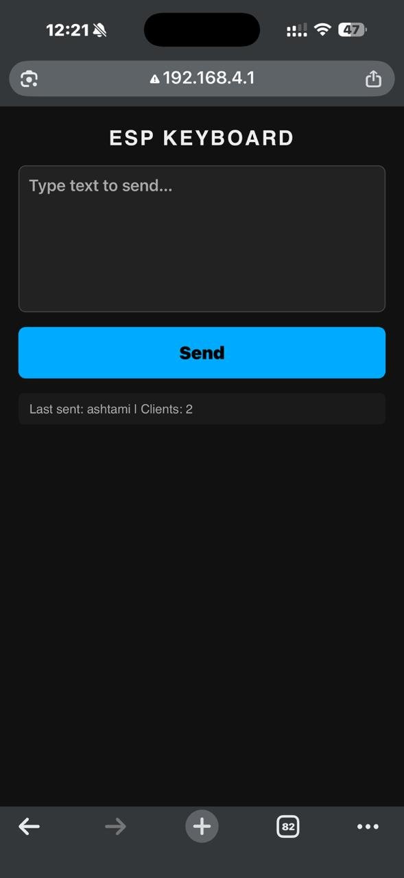
- Web UI test: connect any device to WiFi
ESP_KB(password:12345678) → open192.168.4.1in a browser → type → click Send
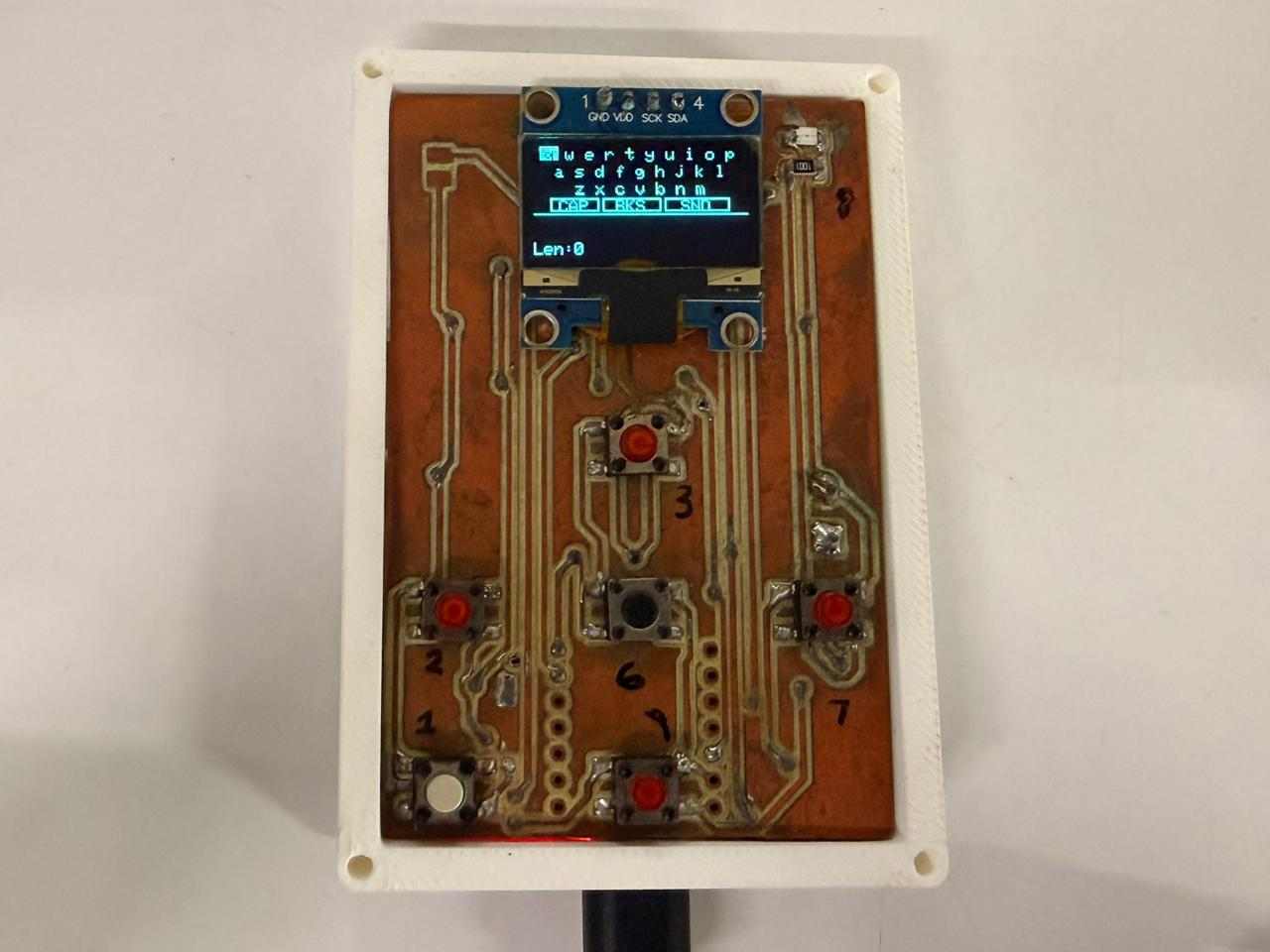
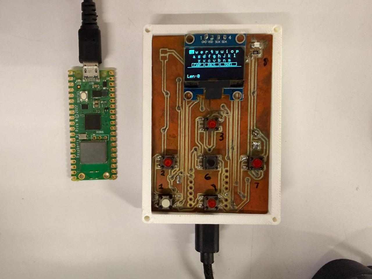
Hero Shots#
Configuration constants#
Everything adjustable is a #define at the top of each file:
esp32_keyboard.ino#
#define AP_SSID   "ESP_KB"          // WiFi network name
#define AP_PASS   "12345678"        // WiFi password
#define STA_SSID  ""               // Home router SSID (leave empty to skip)
#define STA_PASS  ""               // Home router password
#define PICO_IP   "192.168.4.2"    // Pico W static IP
#define PICO_PORT 4210             // UDP port
pico_hid.ino#
#define AP_SSID            "ESP_KB"
#define AP_PASS            "12345678"
#define STATIC_IP          "192.168.4.2"
#define GATEWAY            "192.168.4.1"
#define UDP_PORT           4210
#define CHAR_DELAY_MS      20       // ms between keystrokes
#define RECONNECT_INTERVAL 5000    // ms between reconnect attempts
Phase 2 — Two Targets, One Keyboard#
The extra credit goal was more than two nodes. Phase 1 was already two devices, but they were asymmetric — one sender, one receiver. For Phase 2 I added a third: a Raspberry Pi Pico 2W, its own static IP, its own USB connection to a second PC. Same keyboard, two machines.
The ESP32-C6 side barely changes — it already runs an AP and fires UDP packets, so you basically just give it a second destination IP to aim at. The real work was on the keyboard side: the OLED needed a client picker screen, the web UI needed target selection buttons, and the numbers row was lowkey long overdue anyway.
AI PROMPT USED: “Update my two-device block diagram to a three-device version. Keep the XIAO ESP32-C6 box on the left with the OLED QWERTY + numbers keyboard, a new client-select screen, the WiFi Access Point ESP_KB, and the web server on port 80. On the right, show two separate boxes stacked vertically: a Raspberry Pi Pico W at 192.168.4.2 and a Raspberry Pi Pico 2W at 192.168.4.3, both receiving UDP packets on port 4210 and each outputting USB HID to its own PC. Draw two separate dashed Wi-Fi UDP arrows from the ESP32 box, one to each Pico box, each labelled with its destination IP. Same dark background, monospace font, cyan/green accent style as the first diagram.”
New Hardware — Device 3#
| Component | Role |
|---|---|
| Raspberry Pi Pico 2W (RP2350) | Second USB HID target — static IP 192.168.4.3 |
No extra wiring. Flash pico2w_hid.ino, plug into a second PC via USB, done.
Static IP Assignments#
| Device | IP | UDP Port |
|---|---|---|
| ESP32-C6 | 192.168.4.1 | — |
| Pico W | 192.168.4.2 | 4210 |
| Pico 2W | 192.168.4.3 | 4210 |
Both Picos listen on port 4210 — different IPs, no conflict.
What Changed on the ESP32-C6#
Numbers row added#
The keyboard now has five rows. 1 2 3 4 5 6 7 8 9 0 sits above the Q-row. Numbers are always numeric — CAPS doesn’t touch them, only letters.
Y= 0  1 2 3 4 5 6 7 8 9 0
Y= 8  Q W E R T Y U I O P
Y=16  A S D F G H J K L
Y=24  Z X C V B N M
Y=32  [CAP]  [BKS]  [SND]
Y=40  ────────────────────
Y=42  text buffer
Y=55  Len:xx
Screen cycle — down to two#
The Mode screen is gone. Long-pressing SEND now just toggles between the keyboard and the status screen. Honestly two states are way easier to track when you’re mid-typing and can’t look at code.
| Screen | What it shows |
|---|---|
| 0 — QWERTY | Keyboard + text buffer |
| 1 — Status | AP IP, STA IP, client count, last sent |
Client select screen (new)#
Short-pressing SEND no longer sends immediately — it opens a picker first. This was necessary because with two possible targets, “send” on its own is ambiguous.
┌─────────────────────────────┐
│         Send to:            │
├─────────────────────────────┤
│  >      Pico W              │  ← highlighted when selected
│         Pico 2W             │
│  ^v:sel  SND/SPC:ok  L:bk  │
└─────────────────────────────┘| Button | What it does |
|---|---|
| UP / DOWN | Toggle between Pico W and Pico 2W |
| SEND or SPACE | Confirm — fires UDP to the selected device |
| LEFT | Cancel — back to keyboard, nothing sent |
| Long-press SEND | Skip the picker, jump straight to Status screen |
The on-screen [SND] key and the physical SEND button both open the same picker.
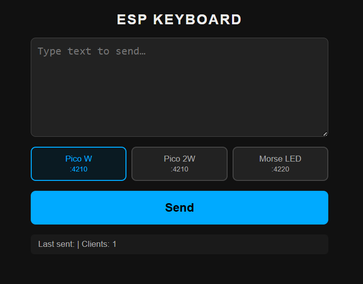
What Changed on the Web UI#
Two toggle buttons now sit above the Send button — click one to pick your target before sending. Pico W (192.168.4.2) is the default. The POST body now includes &client=0 or &client=1 so the ESP32 knows which IP to use.
New File: pico2w_hid/pico2w_hid.ino#
This is basically pico_hid.ino with one line changed. Literally one constant is different:
#define STATIC_IP "192.168.4.3" // Pico 2W — Pico W stays on .2
Everything else — WiFi connection logic, UDP listener, USB HID output, reconnect handling — is identical. The RP2350 (Pico 2W chip) is backwards compatible with the RP2040 for this use case, so no firmware changes were needed beyond the IP.
Uploaded to: Raspberry Pi Pico 2W only.
Full code — pico2w_hid.ino#
#include <WiFi.h>
#include <WiFiUDP.h>
#include <Keyboard.h>   // Philhower core — requires TinyUSB stack

// ─── Configuration ────────────────────────────────────────────
#define LED_PIN     LED_BUILTIN
#define UDP_PORT    4210
#define AP_SSID     "ESP_KB"
#define AP_PASS     "12345678"
#define STATIC_IP   "192.168.4.3"   // Pico 2W — different from Pico W (.2)
#define GATEWAY     "192.168.4.1"
#define SUBNET      "255.255.255.0"

#define CHAR_DELAY_MS       20      // ms between each typed character
#define RECONNECT_INTERVAL  5000    // ms between reconnect attempts
#define WIFI_TIMEOUT_MS     10000   // ms to wait for initial connection
#define LED_BLINK_MS        80      // LED on duration per blink

// ─── Globals ──────────────────────────────────────────────────
WiFiUDP udp;
char packetBuf[512];

unsigned long lastReconnectAttempt = 0;
bool          udpReady             = false;

// LED blink state (non-blocking)
bool          ledOn     = false;
unsigned long ledOnTime = 0;

// ─── Forward declarations ────────────────────────────────────
void connectWiFi();
void typeText(const char* text, int len);
void blinkLED();
void updateLED();

// ─────────────────────────────────────────────────────────────
void setup() {
  Serial.begin(115200);
  delay(500);

  pinMode(LED_PIN, OUTPUT);
  digitalWrite(LED_PIN, LOW);

  Keyboard.begin();
  Serial.println("[HID] Pico 2W keyboard initialised");

  connectWiFi();
}

// ─────────────────────────────────────────────────────────────
void loop() {
  // ── Auto-reconnect if WiFi dropped ──────────────────────────
  if (WiFi.status() != WL_CONNECTED) {
    udpReady = false;
    unsigned long now = millis();
    if (now - lastReconnectAttempt >= RECONNECT_INTERVAL) {
      lastReconnectAttempt = now;
      Serial.println("[WiFi] Disconnected — reconnecting…");
      connectWiFi();
    }
  }

  // ── Handle incoming UDP packets ─────────────────────────────
  if (udpReady) {
    int packetSize = udp.parsePacket();
    if (packetSize > 0) {
      int len = udp.read(packetBuf, sizeof(packetBuf) - 1);
      if (len > 0) {
        packetBuf[len] = '\0';

        Serial.print("[UDP] Received (");
        Serial.print(len);
        Serial.print(" bytes): ");
        Serial.println(packetBuf);

        blinkLED();
        typeText(packetBuf, len);
      }
    }
  }

  updateLED();
}

// ─── WiFi connection ─────────────────────────────────────────
void connectWiFi() {
  Serial.print("[WiFi] Connecting to ");
  Serial.println(AP_SSID);

  IPAddress ip, gw, sn;
  ip.fromString(STATIC_IP);
  gw.fromString(GATEWAY);
  sn.fromString(SUBNET);
  WiFi.config(ip, gw, sn);

  WiFi.begin(AP_SSID, AP_PASS);

  unsigned long start = millis();
  while (WiFi.status() != WL_CONNECTED) {
    if (millis() - start > WIFI_TIMEOUT_MS) {
      Serial.println("[WiFi] Timeout — will retry later");
      return;
    }
    delay(200);
    Serial.print('.');
  }

  Serial.println();
  Serial.print("[WiFi] Connected, IP: ");
  Serial.println(WiFi.localIP());

  udp.stop();
  udp.begin(UDP_PORT);
  udpReady = true;
  Serial.print("[UDP] Listening on port ");
  Serial.println(UDP_PORT);
}

// ─── Type text via USB HID ───────────────────────────────────
void typeText(const char* text, int len) {
  int typeLen = len;

  // Remove single trailing newline added by the sender
  if (typeLen > 0 && text[typeLen - 1] == '\n') {
    typeLen--;
  }

  for (int i = 0; i < typeLen; i++) {
    char c = text[i];
    if ((c >= 32 && c <= 126) || c == '\n' || c == '\t') {
      Keyboard.write(c);
      delay(CHAR_DELAY_MS);
    }
  }

  Serial.println("[HID] Typing complete");
}

// ─── LED blink (non-blocking) ────────────────────────────────
void blinkLED() {
  digitalWrite(LED_PIN, HIGH);
  ledOn     = true;
  ledOnTime = millis();
}

void updateLED() {
  if (ledOn && (millis() - ledOnTime >= LED_BLINK_MS)) {
    digitalWrite(LED_PIN, LOW);
    ledOn = false;
  }
}
Arduino IDE settings — Pico 2W#
| Setting | Value |
|---|---|
| Board | Raspberry Pi Pico 2 W |
| USB Stack | Adafruit TinyUSB ← same requirement as Pico W |
| Flash Size | 4MB |
Hero Shots#
Updated Configuration Constants#
esp32_keyboard.ino (Phase 2)#
#define AP_SSID    "ESP_KB"
#define AP_PASS    "12345678"
#define PICO_IP    "192.168.4.2"   // Pico W
#define PICO2_IP   "192.168.4.3"   // Pico 2W
#define PICO_PORT 4210pico2w_hid.ino#
#define AP_SSID            "ESP_KB"
#define AP_PASS            "12345678"
#define STATIC_IP          "192.168.4.3"
#define GATEWAY            "192.168.4.1"
#define UDP_PORT           4210
#define CHAR_DELAY_MS      20
#define RECONNECT_INTERVAL 5000
Testing Methodology#
I tested in layers, bottom-up, and only moved on once the layer below worked. That way, when something broke, the broken part was almost always the layer I just added.
| # | Layer | Pass looks like |
|---|---|---|
| 1 | OLED over I2C | Boot screen, then the QWERTY grid (else display.begin() failed at 0x3C) |
| 2 | Buttons | Cursor moves one cell per press, letters land in the buffer |
| 3 | WiFi join | Pico’s Serial Monitor prints [WiFi] Connected and [UDP] Listening |
| 4 | UDP path | Pico prints [UDP] Received (n bytes): <text> |
| 5 | USB HID | Text types itself into Notepad |
Two extra checks let me test without the buttons: sending from the web UI uses the same UDP path, so if web works but the OLED doesn’t, the bug is in my button code; and the Status screen shows the live client count, so I can confirm a Pico joined without plugging the ESP32 into a PC. For Phase 2 I ran layers 3 to 5 once per Pico, then checked that “send to Pico W” only typed on PC 1, to prove the picker routes correctly.
Failures and How I Fixed Them#
Nothing worked first try. Each fix is still sitting in the final code.
| Failure | Cause | Fix |
|---|---|---|
| ESP32-C6 couldn’t be the keyboard at all | No USB OTG, only Serial/JTAG | Split the job: ESP32 does the network, a Pico W does the USB typing. This is why it’s a two-board design. |
| Fast typing dropped letters (“Helo Word”) | Pico typed faster than the OS could read | 20ms gap between keys (CHAR_DELAY_MS) |
| Pico went deaf after the ESP32 rebooted | Old UDP socket leaked on reconnect | udp.stop() before udp.begin(), plus a 5s auto-reconnect timer |
| One press counted as several | Switch bounce | 50ms debounce (pin must hold steady before it counts) |
| SPACE did the wrong thing | One button, two jobs | One tap selects a letter, two taps (within 300ms) types a space |
| “Send” went to the wrong Pico | Two targets, no way to choose | Client picker on the OLED + two target buttons on the web UI |
| HID typed nothing even though packets arrived | Wrong IDE setting | Set USB Stack to Adafruit TinyUSB, re-flash |
| (Group) Nothing came through | Both sides didn’t agree on SSID/IP/port | Match all three exactly, then it works every time |
The two that taught me the most: not every bug is in your code (the TinyUSB setting), and reconnecting isn’t just connecting again (you have to free the old socket first, or it silently breaks).
How I Debugged#
You can’t put a breakpoint on a wireless packet, so I used four things, and each one answers one yes/no question that cuts the system in half:
- Tagged Serial logs (
[WiFi],[UDP],[HID],[SEND→PicoW]): the last tag printed shows how far the data got before it stopped. - The Pico’s LED, which blinks the instant a packet arrives, before typing: LED blinks but no text means the bug is in the typing; no blink means the packet never arrived.
- The web UI, which shares the UDP path: web works but OLED doesn’t means the bug is in the buttons, not the network.
- The Status screen, which shows the client count and last sent, so I can read the ESP32’s state without a cable.
AI Usage and Credits#
Being honest about where AI helped is part of documenting this properly.
Used AI for: the two block diagrams (prompts shown next to each), a first version of the firmware (prompt shown in Software Architecture), and proofreading this page. Tool used: Claude by Anthropic.
Did myself: all the hardware (the Week 8 PCB, soldering, wiring, the two and three board setup), every test and fix in the Failures section (those bugs only showed up on real boards), and the design choices (AP mode, UDP over TCP, two chips because of the USB limit, the SPACE tap timing).
Note: the AI prompts shown were rebuilt from the finished diagrams and code after the fact, not saved when they were first written.
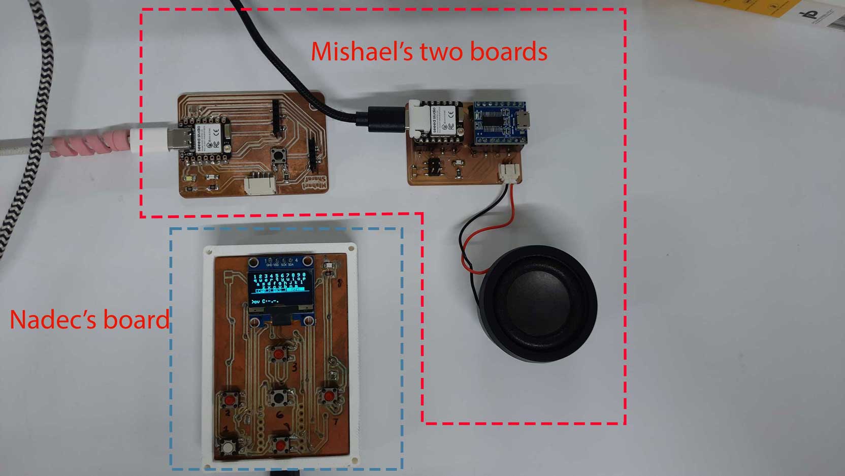
Group Assignment#
The link to our group assignment is below: Group Assignment
The group task this week was to send a message between two different projects. Basically, two teams each had their own boards doing their own thing, and we had to get them to talk to each other over a network.
My wireless keyboard system actually fit this goal pretty well, since it was already built around one board sending data to another over WiFi UDP. So for the group test, we used the same idea: one board sends a small message, the other board receives it and does something with it. The main thing we learned is that as long as both boards agree on the same WiFi network, the same IP address, and the same port number, the actual “talking” part is simple. Most of the problems we ran into were not about the code, they were about both sides not agreeing on those three things. Once the addresses matched up, the message went through every time.
It was a good reminder that networking is less about writing complicated code and more about being careful and exact with small details like IP addresses and ports.
The above code was written with the assistance of Claude by Anthropic.
The Above documentation was proofread and grammatical errors were corrected by Claude by Anthropic.
AI PROMPT USED: “Proofread the following text and correct any grammatical errors and spelling mistakes.”
Note: the AI prompts shown for the block diagrams and firmware were reconstructed by Claude by Anthropic from the finished diagrams/code itself, not logged at the time they were originally made.