Week 05 - 3D Scanning and Printing#
Week 5 focused on 3D scanning and printing, exploring additive manufacturing technologies and reverse engineering objects through scanning.
The aim was to understand design rules for 3D printing, test printer capabilities, and explore 3D scanning workflows.
This week continued the digital fabrication journey, adding additive manufacturing to the subtractive processes learned earlier.
Group Assignment#
- Test the design rules for your 3D printers
- Characterize your printer(s):
- Dimensions
- Tolerances
- Surface quality
- Support requirements
Individual Assignment#
- Design and 3D print an object that could not be easily made subtractively
- 3D scan an object, try to prepare it for printing
Extra Credit Goals
- Try different printing processes
- Try different scanning processes
Software Used#
- CAD Software for designing 3D printable objects - I used SolidWorks for the lattice structure and Fusion 360 for the engine model.
- Slicer Software for preparing prints - I used Bambu Studio for slicing and generating G-code.
- 3D Scanning Software for capturing and processing scans - I used the Artec Studio software for processing the Artec Leo scans and the Kiri Engine app for photogrammetry and Iphone Lidar Scan.
- Browser + Git for documentation
Weekly Schedule#
| Day | What I Did |
|---|---|
| WED | Lecture on 3D scanning and printing |
| THU | Group Assignment - Bambu A1, Prusa XL, Bambu X1C, Formlabs |
| FRI | Introduction To 3D Scanning |
| SAT | Designing For 3d Printing |
| SUN | Continuation of design work |
| MON | 3d Scanning and post processing |
| TUE | Regional review |
Week 05 – 3D Printing and Scanning#
The assignment for this week was to:
- Design, document, and 3D print an object that could not be made subtractively
- 3D scan an object and optionally 3D print it
Group Assignment#
🔗 https://fabacademy.org/2026/labs/kochi/group_assignmetns/week05/
Overview#
As part of the group assignment, we focused on understanding the design rules and physical limitations of our 3D printers by printing and analyzing test geometries.
The goal was to experimentally determine:
- Maximum bridging length
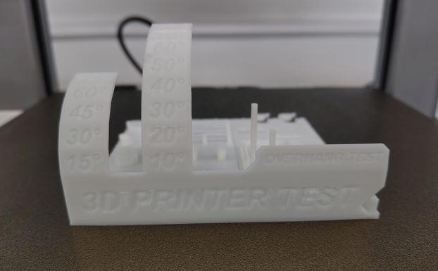
- Maximum overhang angle without supports
- Minimum clearance between moving parts
- Wall thickness limits
- Dimensional accuracy
Observations and Learnings#
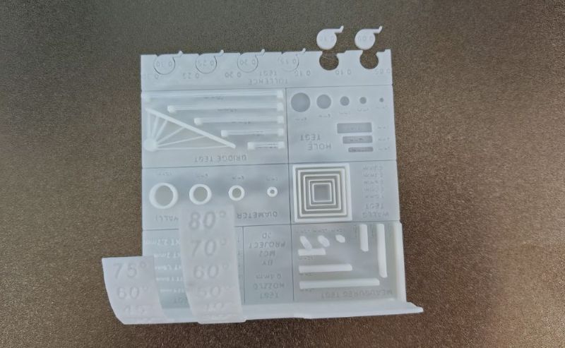
Bridging:
The printer was able to handle bridges up to ~20 mm effectively. Beyond this, sagging and stringing began to occur.Overhangs:
Angles up to 45° printed cleanly without supports. Angles beyond this required support structures for good surface quality.Clearances:
Small gaps are critical for moving parts. Insufficient clearance leads to fused components. Generally keep the clearance greater than 0.3mm for PLA.Supports and Orientation:
Print orientation plays a major role in reducing the need for supports and improving surface finish.
Importance#
This testing directly influenced my individual designs, ensuring:
- No unnecessary supports
- Better print quality
- Functional print-in-place mechanisms
Subtractive vs Additive Manufacturing#
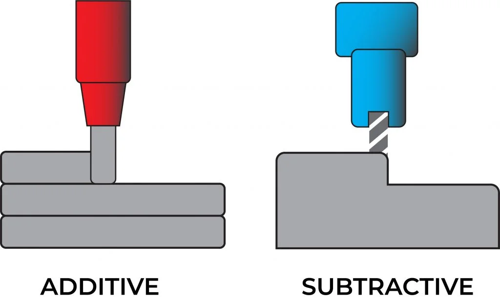 img source : https://www.radsourcing.com/blog/additive-and-subtractive-manufacturing/
| Subtractive Manufacturing | Additive Manufacturing |
|---|---|
| Material is removed from a block | Material is added layer by layer |
| Examples: CNC, milling, turning | Example: FDM 3D printing |
| Limited by tool accessibility | Can create internal geometries |
| Generates material waste | Minimal waste |
| Requires multiple setups for complex parts | Can produce complex parts in one go |
Key Insight#
Additive manufacturing enables:
- Internal cavities
- Lattice structures
- Print-in-place assemblies
These are impossible or extremely difficult using subtractive methods.
Individual Assignment#
Machine and Material#
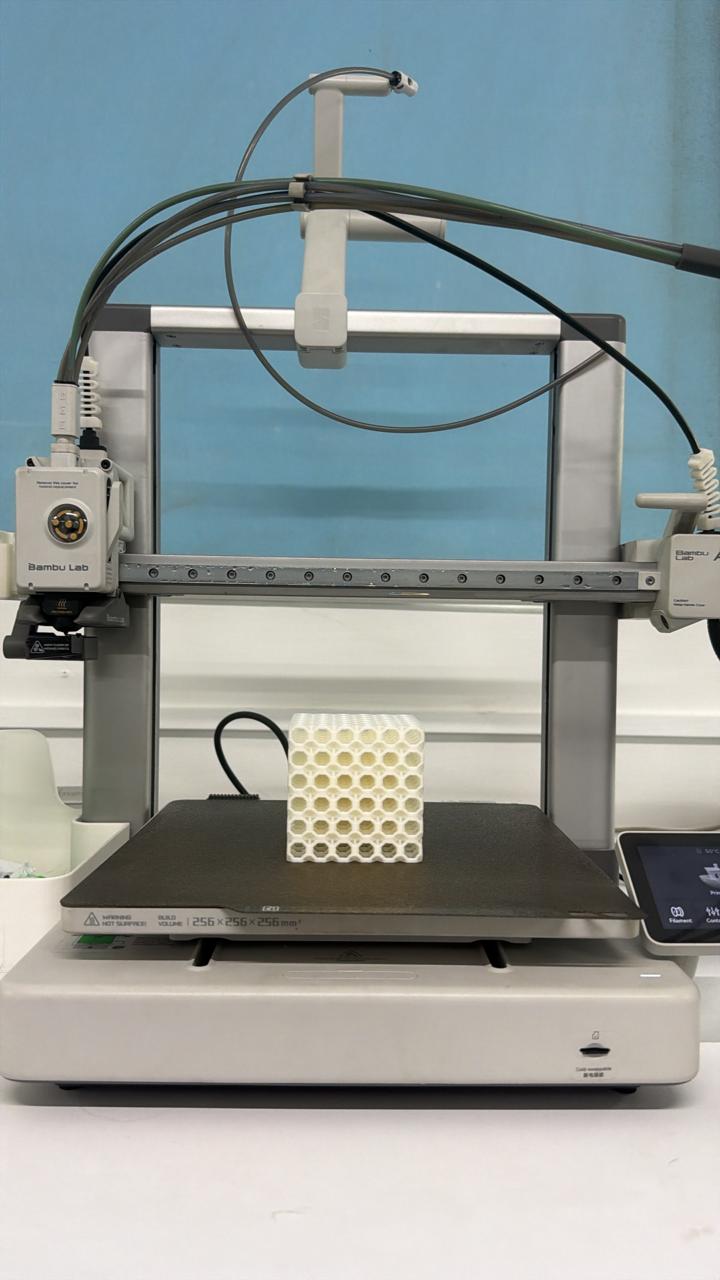
I used my personal Bambu Lab A1 3D printer along with WOL3D PLA filament. https://bambulab.com/en-in/a1
Filament Specifications#
https://wol3d.com/product/pla-black-3/
- Print Temperature: 190°C – 220°C
- Bed Temperature: 50–60°C
- Shrinkage / Warping: Minimal
- Diameter: 1.75 mm
Since I am very familiar with both the printer and filament, the process was smooth. I used the default Generic PLA settings in Bambu Studio.
Items Designed and Printed#
I designed and 3D printed three items.
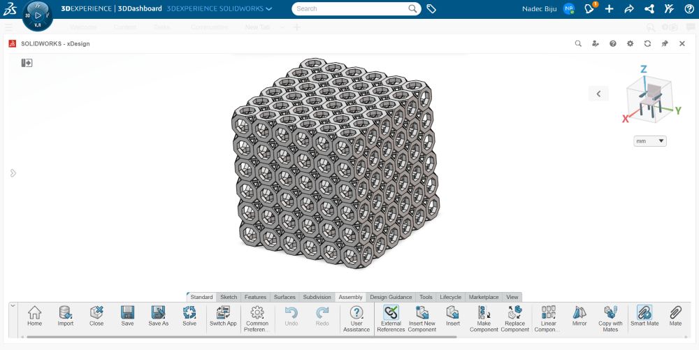
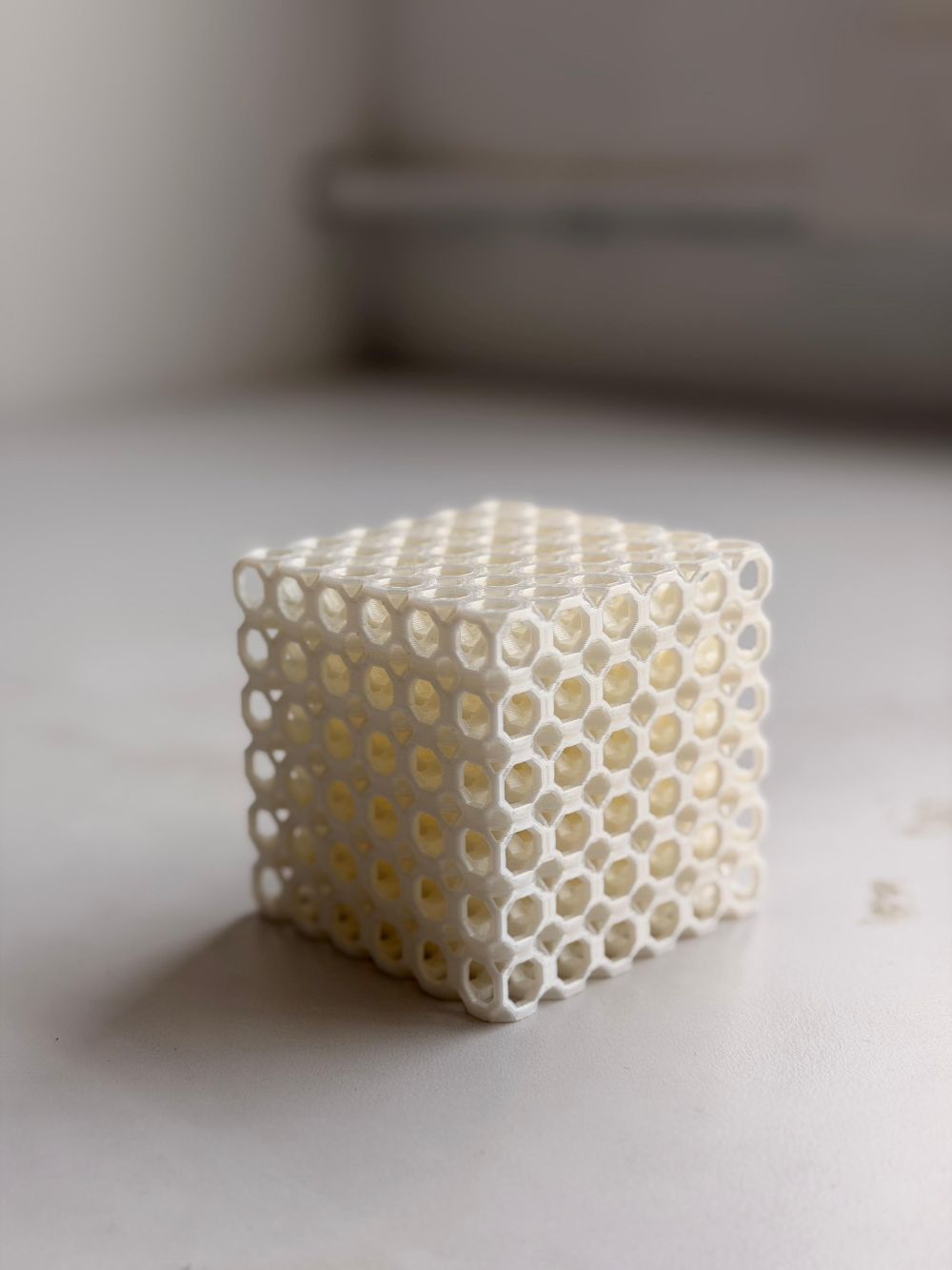
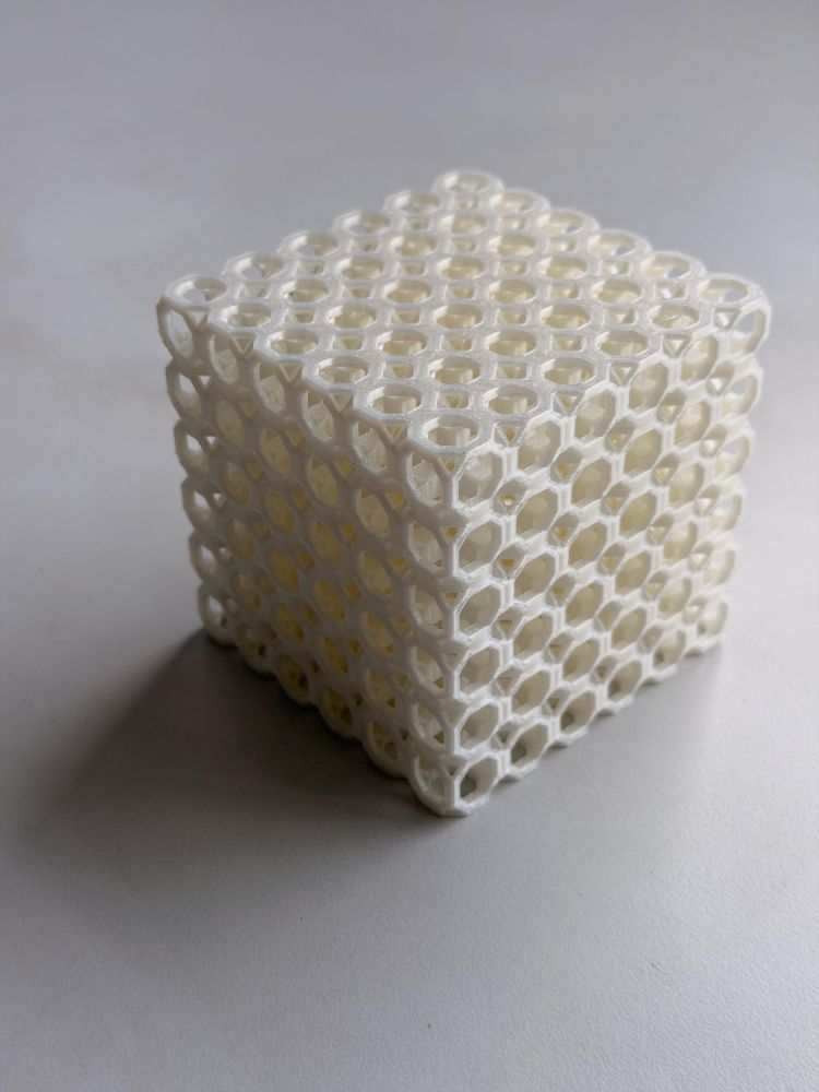
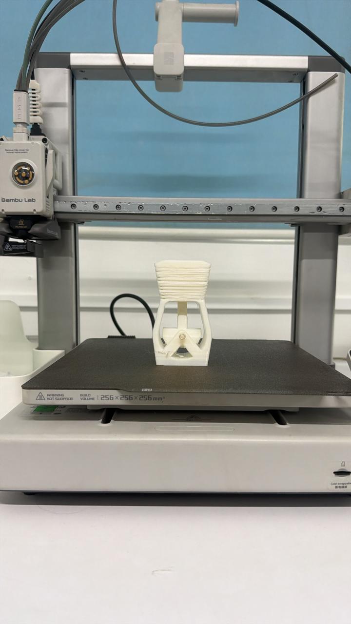
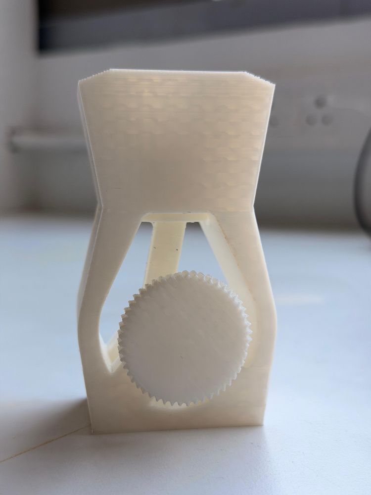
Item 1 – 3D Octagonal Lattice Structure#
Design Process#
- Opened SolidWorks
- Created a single octagonal unit cell
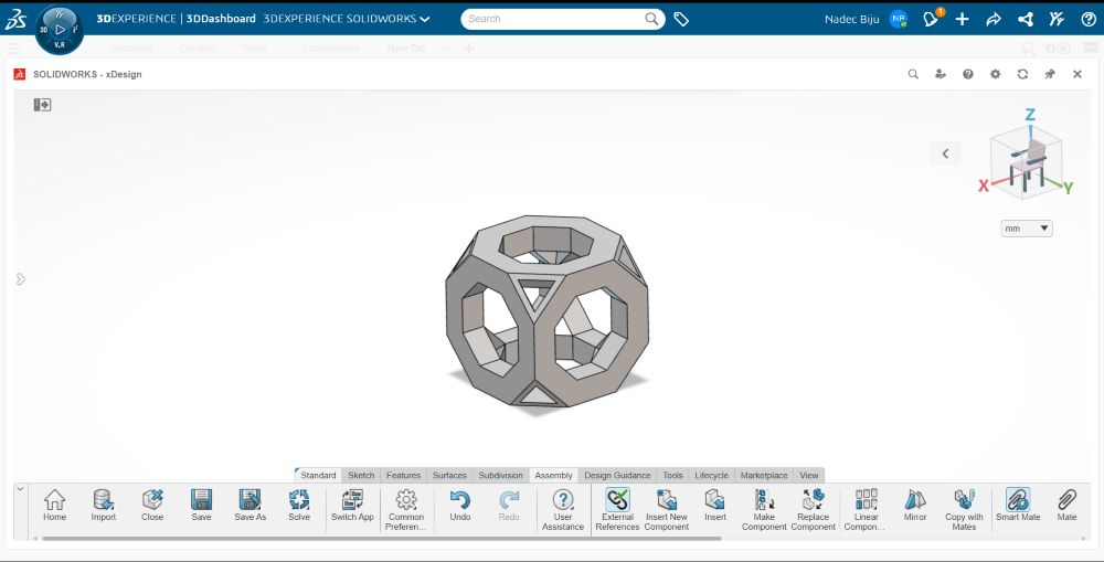
- Used linear patterning in assembly to form the full lattice
Design Considerations#
From group assignment results:
- Bridge lengths < 20 mm
- Overhang angles < 45°
Bridging (Detailed)#
Bridging occurs when filament is extruded across a gap with no support.
- If too long → filament sags due to gravity
- Keeping it under 20 mm ensures:
- Clean spans
- Minimal drooping
- Structural integrity
Overhangs (Detailed)#
Overhang angle determines how much of a layer is supported.
- Below 45° → each layer is supported by the previous one
- Above 45° → material prints into air → poor finish
By keeping within limits:
- No supports required
- Faster print
- Cleaner output
Printing Process#
Bambu Studio is the slicer software made by Bambu Lab. A slicer takes a 3D model (STL/3MF) and converts it into G-code, which is just a list of instructions the printer understands — where to move, how fast, when to push out filament, when to heat up, etc. Without slicing, the printer has no idea what to do with a 3D model.
🔗 https://bambulab.com/en-in/download/studio
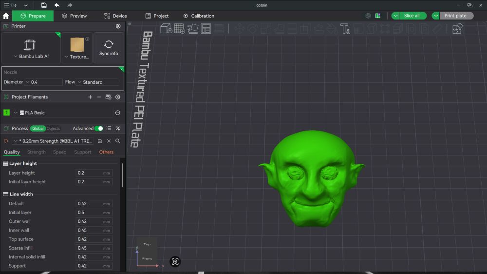
Step 1 — Setting up the project
When I opened Bambu Studio, the first thing I did was select my printer (Bambu Lab A1) and the filament I had loaded (Generic PLA). These two settings tell the slicer what kind of bed size to work with and how to behave thermally (nozzle temperature, bed temperature, cooling fan curves, retraction, etc.).
Step 2 — Importing the model
I dragged my exported lattice STL file straight into the Bambu Studio window. It dropped onto the virtual build plate as an object. In Bambu Studio, anything you drop onto the plate becomes an object — you can have multiple objects on one plate, move them around, rotate them, scale them, or duplicate them. Each object on the plate gets sliced together as one print job.
Step 3 — Orienting the model
I positioned the lattice flat on the bed so the largest face was touching the build plate. This matters because the first layer is what holds everything else up, and a wider base = more grip + less chance of the print peeling off mid-job. I also made sure no overhangs exceeded the ~45° rule I tested earlier, so I wouldn’t need supports.
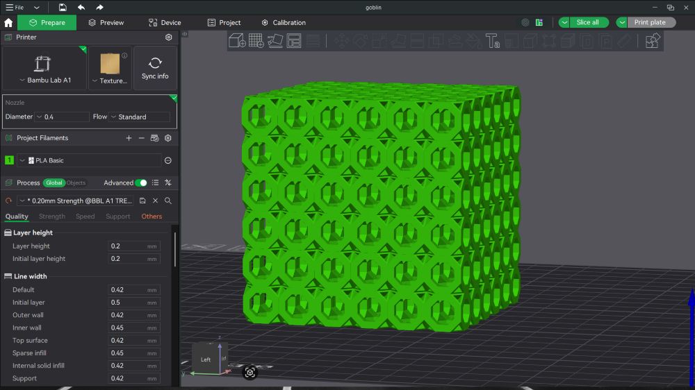
Step 4 — Slice settings
For this print I used:
- Layer height: 0.2 mm — a good balance between speed and surface quality. Bigger numbers = faster but rougher; smaller = slow but smoother.
- Infill: kept at Bambu’s default for the Generic PLA preset, since the lattice geometry is mostly hollow by design.
- Supports: OFF — the design was specifically built to stay within self-supporting overhang angles.
- Build plate: Cool Plate / Textured PEI (Bambu A1 default).
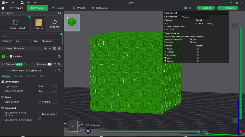
Step 5 — Slicing
I clicked the “Slice plate” button. Bambu Studio chewed through the model and showed the layer-by-layer toolpath preview — every move the nozzle would make, color-coded by feature (wall, infill, support, travel, etc.). I scrubbed through the layers using the slider on the right side to sanity-check that nothing weird was happening — no missing layers, no floating islands, no over-aggressive bridging.
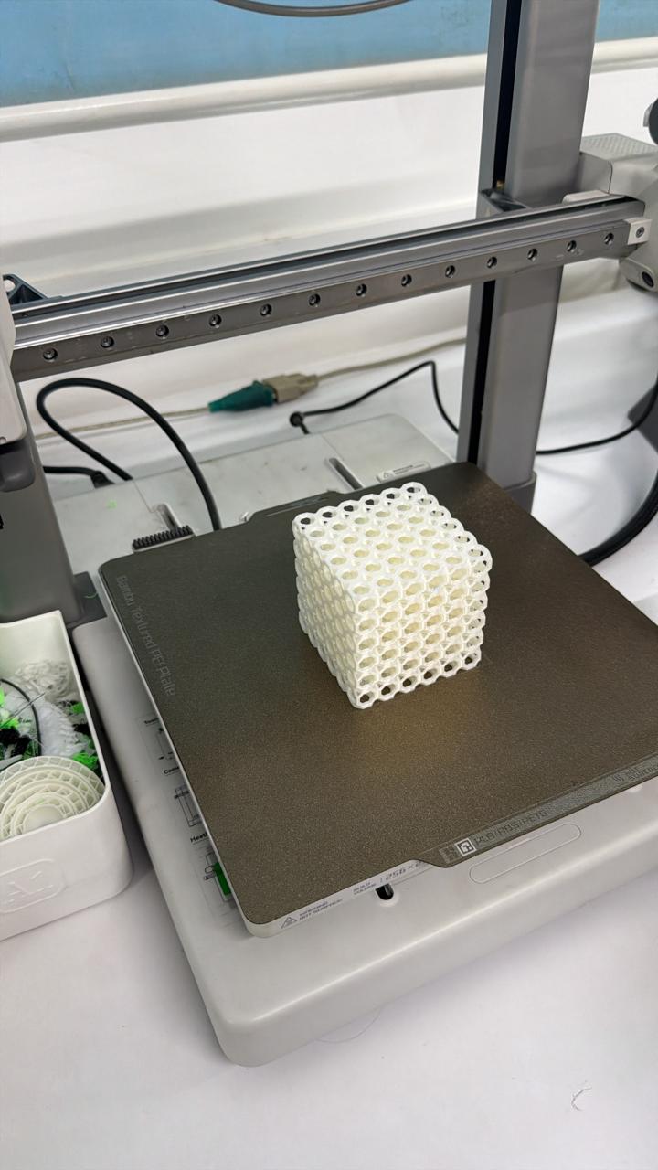
Step 6 — Sending to the printer
I hit “Print Plate” which uploads the sliced job (now a .3mf / G-code bundle) straight to the printer over Wi-Fi. The A1 picked it up, ran its auto bed-leveling routine, and started the print.
Hero Shots#
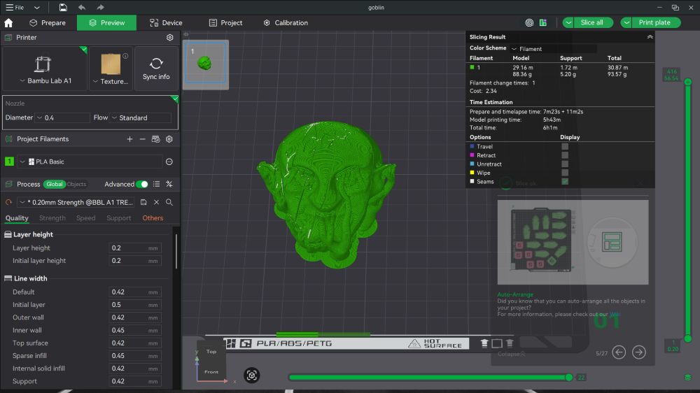
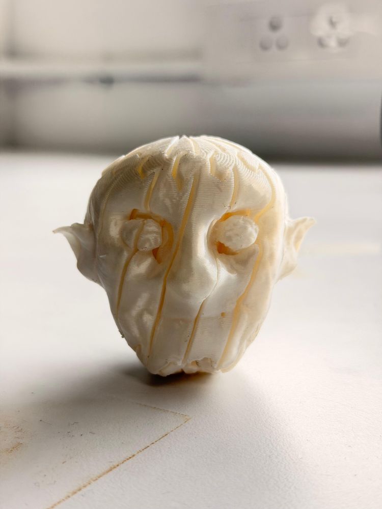
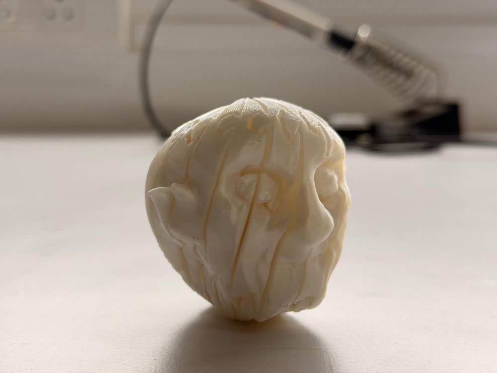
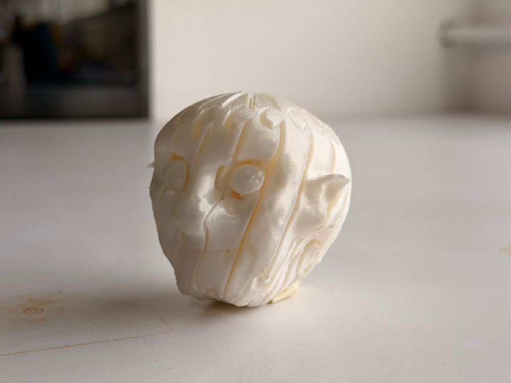
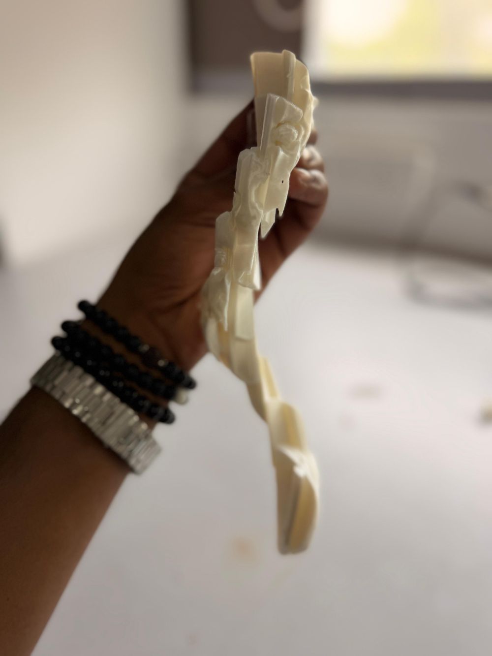
Item 2 – Goblin Flexi Toy#
While scrolling through Instagram, I came across:
🔗 https://www.instagram.com/piodeer.stl/
They had posted a reel on making a flexi toy, which inspired me.
I decided to convert the Goblin model I created in Week 2 (Blender) into a flexi toy.
🔗 View Goblin Model Creation in Week 2
Process#
- Contacted the creator and obtained a cutter file
- Discussed with instructor Saheen
- Was instructed to design my own cutter
Design Workflow#
- Studied the reference cutter
- Designed my own version from scratch
- Imported both files into Bambu Studio:
Goblin → Positive body
Cutter → Negative body
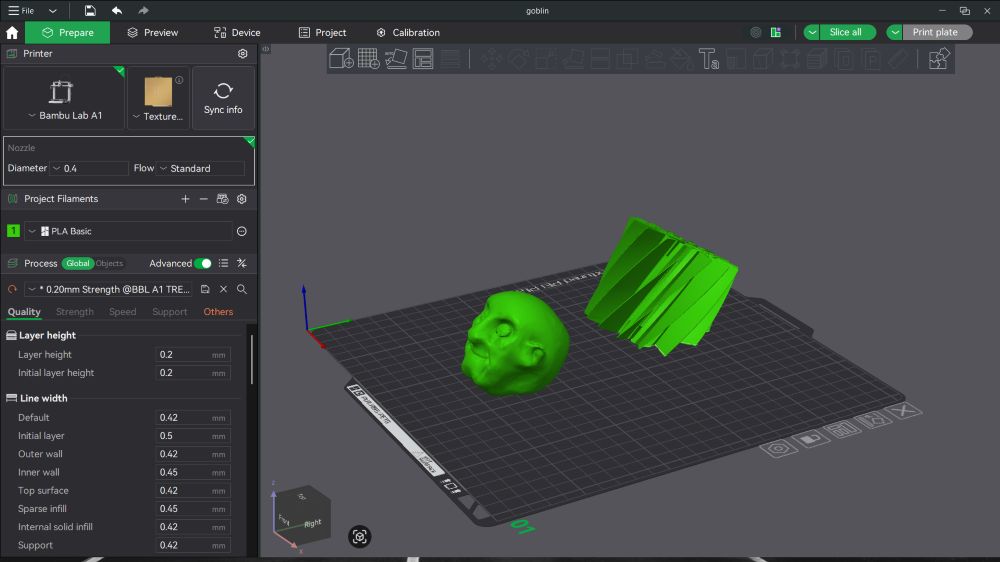
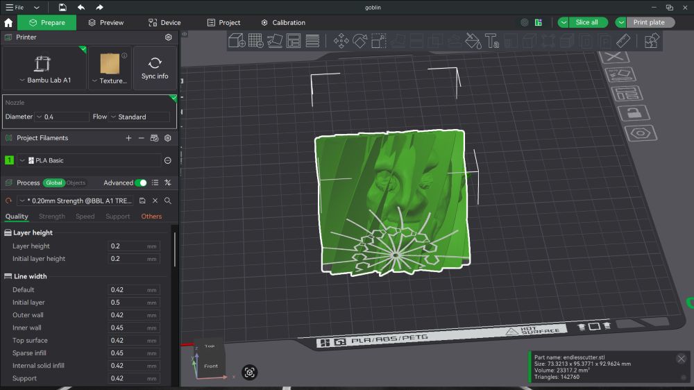
Placing the cutter in the correct position to create the flex channels
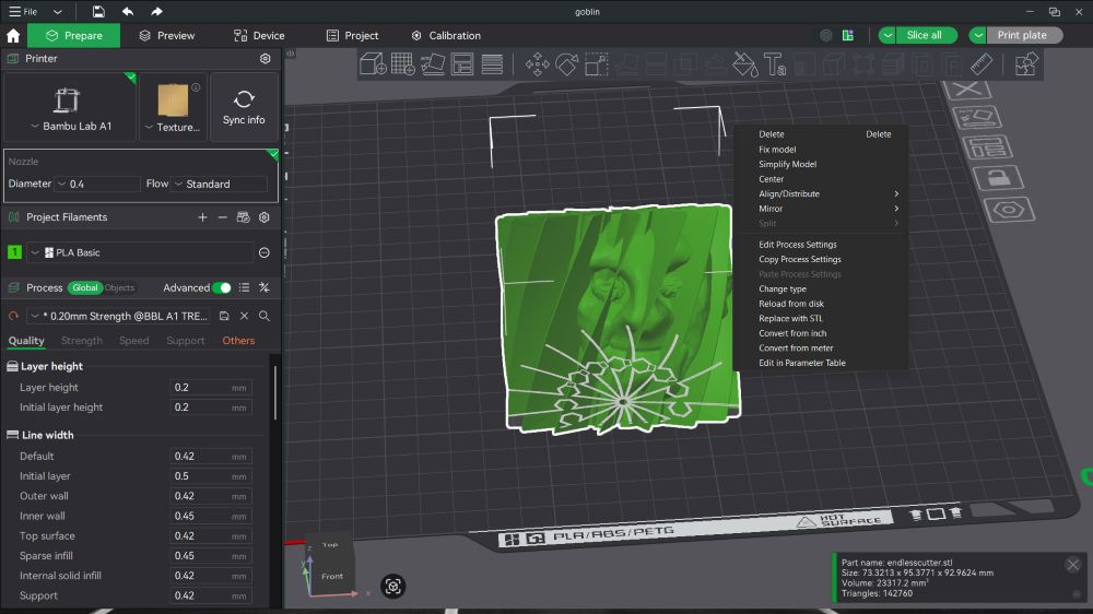
 Right click on the cutter and select change type
 In types select negative part
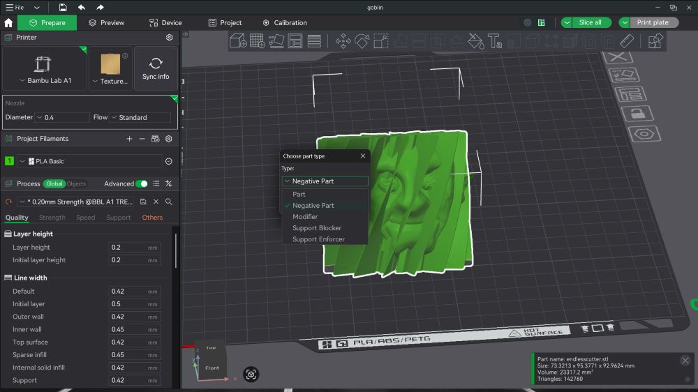 Then click slice and the software will automatically perform the boolean operation to create the flex channels in the goblin model
- Performed boolean merge
Printing Process#
- Sliced the model
- Selected Print Plate
- Sent to printer
- Print started
Hero Shots#
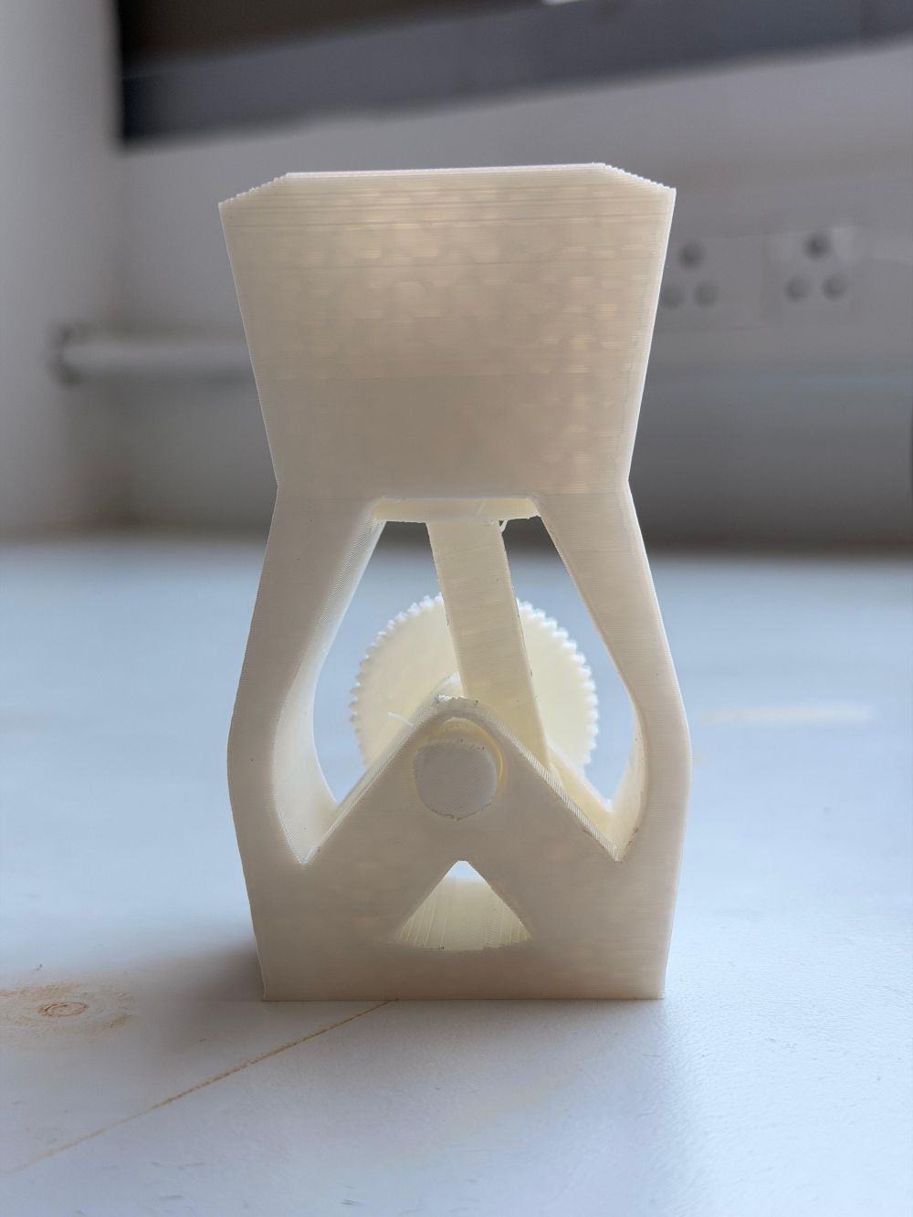
Item 3 – Print-in-Place Engine Model#
I was asked by Saheen to design something that combines:
- Clearances
- Bridging
- Print-in-place functionality
Concept#
Initially planned a car, but instead designed a simple engine model with:
- Crankshaft
- Piston
- Connecting rod
- Casing
Design Process#
- Used Fusion 360 (hybrid modeling)
- Created multiple interacting components
- Ensured all parts are printable as a single assembly
Key Considerations#
- Clearances: Prevent fusion of moving parts
- Bridging: Maintain unsupported spans within limits
- Assembly-free: Fully print-in-place
Printing Process#
- Imported into Bambu Studio
- Arranged on plate
- Sliced with:
- 0.2 mm layer height
- tree supports
- Sent to printer and printed
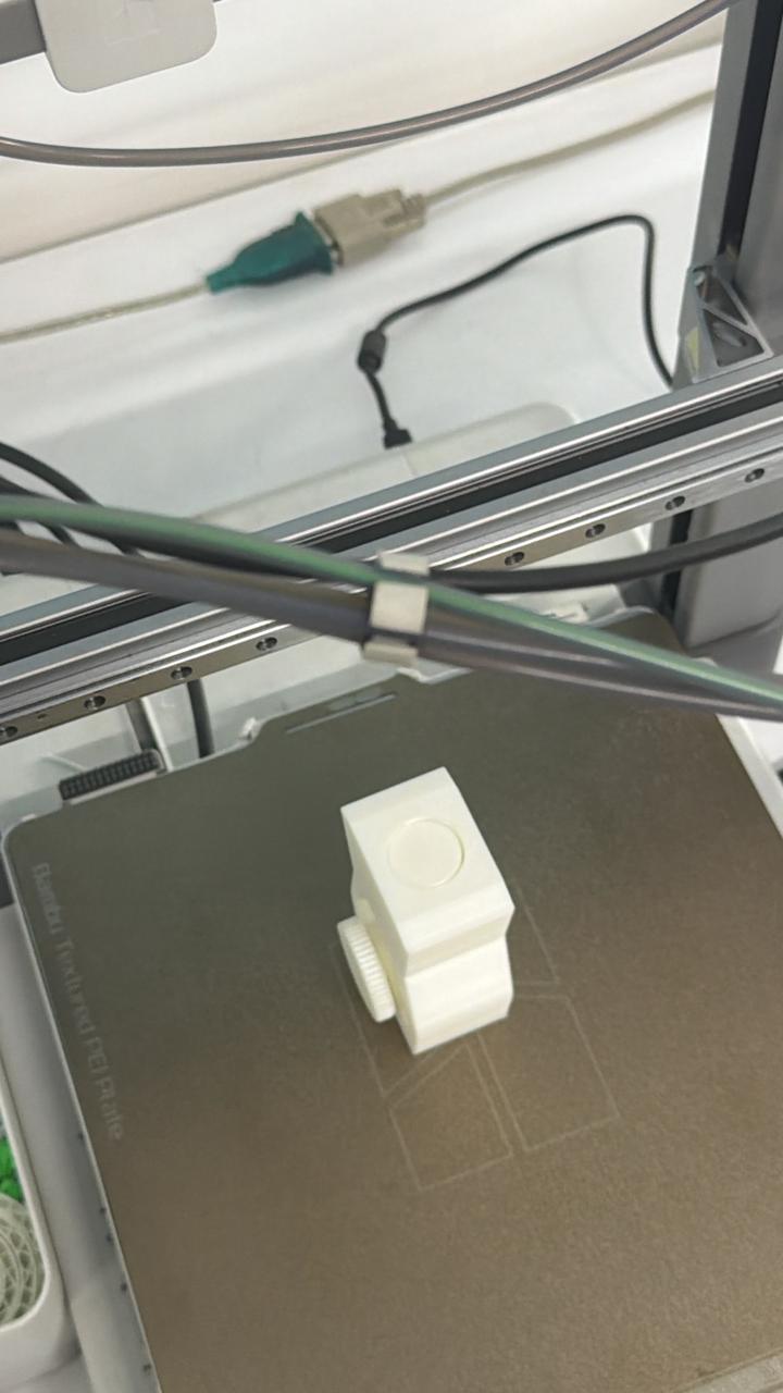
Hero Shots#
Conclusion (3D Printing)#
This completes my three designed prints:
- Lattice structure
- Flexi goblin toy
- Print-in-place engine
Each demonstrates different strengths of additive manufacturing.
Why These Designs Cannot Be Made Subtractively#
Item 1 – Octagonal Lattice Structure#
Why subtractive doesn’t work:
- Has hollow sections inside that can’t be reached by cutting tools
- Making it with subtractive methods would waste ~90% of the material
- Multiple cuts would weaken the connections between lattice pieces
Why 3D printing works:
- Builds the structure layer-by-layer with hollow spaces already in place
- No material waste
- All connections stay strong
Item 2 – Goblin Flexi Toy#
Why subtractive doesn’t work:
- Needs thin, flexible walls that would break during cutting
- Requires precise channels for movement—hard to cut without damaging the model
- All the articulation channels need to be part of one piece
Why 3D printing works:
- Prints as one complete piece with all flex channels built in
- The walls stay intact during printing
- Flexible right after printing
Item 3 – Print-in-Place Engine Model#
Why subtractive doesn’t work:
- Has moving parts inside (crankshaft, piston) that need to work together
- Can’t mill all parts together—each piece would need to be made separately and then assembled
- Hard to get exact clearances between moving parts when assembling by hand
Why 3D printing works:
- Prints as one complete assembly with everything in the right place
- Clearances are already built into the design
- Engine works immediately after printing—no assembly needed
Failures and Learnings#
Coming to the most important part of my 3D printing week — failures and what I learned from them.
Most of the issues I faced were during the engine model print, which involved complex geometry, clearances, and print-in-place mechanisms.
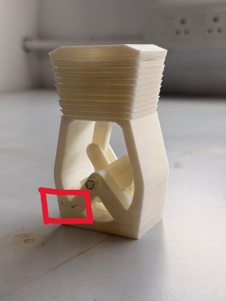
Failure 1 – Power Failure During Print#
During one of the prints, there was a power cut, and although the printer resumed the job, it resulted in a visible defect.
Issue#
- The print resumed after interruption
- The layer at the restart point did not adhere properly
- A clear layer line / weak interface was visible
Why This Happened#
- The previously printed layer had cooled down
- When printing resumed:
- Poor interlayer bonding occurred
- Slight misalignment may have been introduced
- Resulted in:
- Weak structural region
- Visible surface defect
Learning#
- Power interruptions can significantly affect print integrity
- Critical prints should ideally:
- Be done with stable power
- Or use power backup systems (UPS)
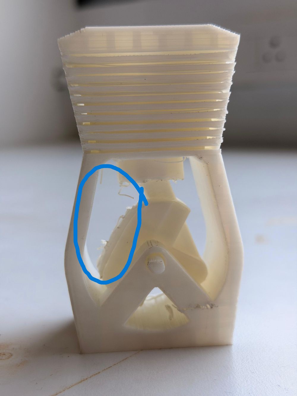
Failure 2 – Improper Support at Crankshaft#
Another major issue occurred at the crankshaft region of the engine model.
Issue#
- Insufficient support under certain features
- Resulted in:
- Sagging
- Deformation
- Poor surface finish
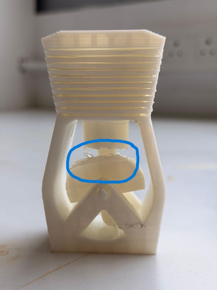
Why This Happened#
- Some areas exceeded:
- Safe overhang limits
- Safe bridging limits
- Lack of support led to:
- Unsupported extrusion
- Gravity-induced deformation
Learning#
- Even when designing for no supports, careful inspection is needed
- Important to:
- Analyze model orientation
- Identify hidden overhangs
- Balance between design constraints and printability
Key Takeaways#
- Real-world printing is not just about design — execution matters equally
- Failures provided deeper insights into:
- Material behavior
- Machine limitations
- Design-for-print principles
These failures helped refine my understanding of:
- Bridging limits
- Overhang handling
- Importance of print stability
Overall, these mistakes were extremely valuable and helped me improve both my design approach and printing strategy for future projects.
3D Scanning#
I explored two different workflows:
Workflow 1 – Artec Leo Scanner#
https://www.artec3d.com/portable-3d-scanners/artec-leo/
- Turned on the Artec Leo scanner
- Selected New Project
- Adjusted distance to avoid background capture
- Started scanning
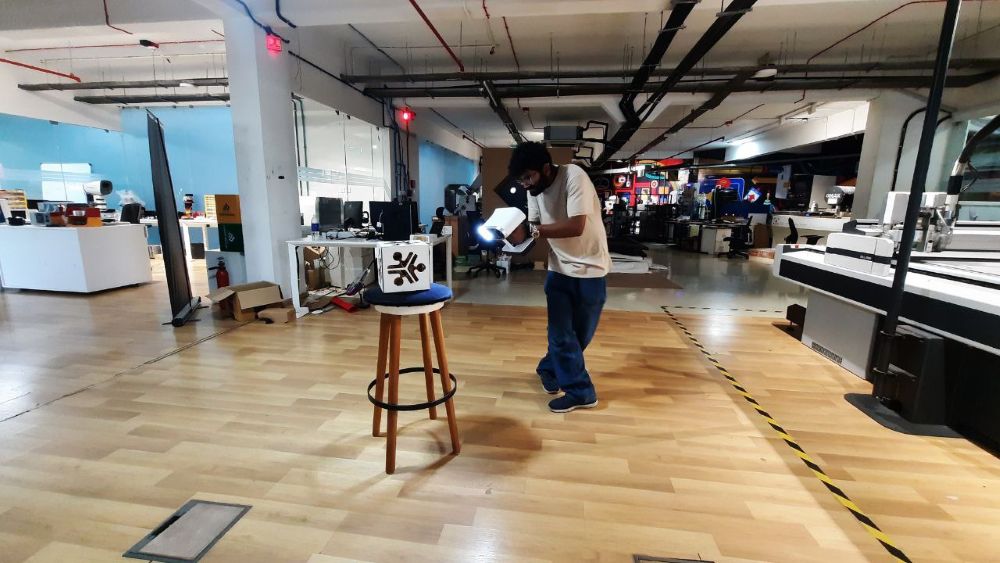
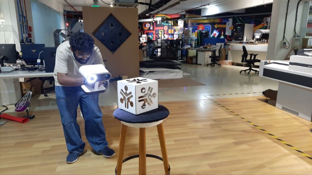
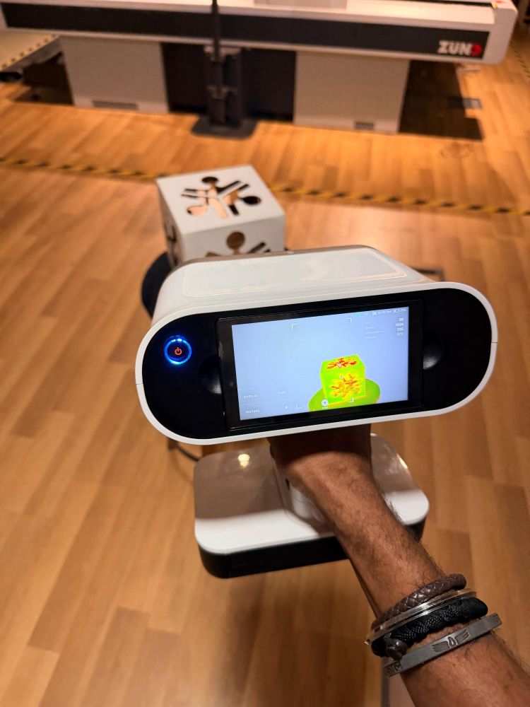
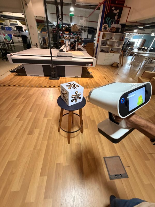
- Completed scan
- Exported to Artec Studio for post-processing https://www.artec3d.com/3d-software/artec-studio
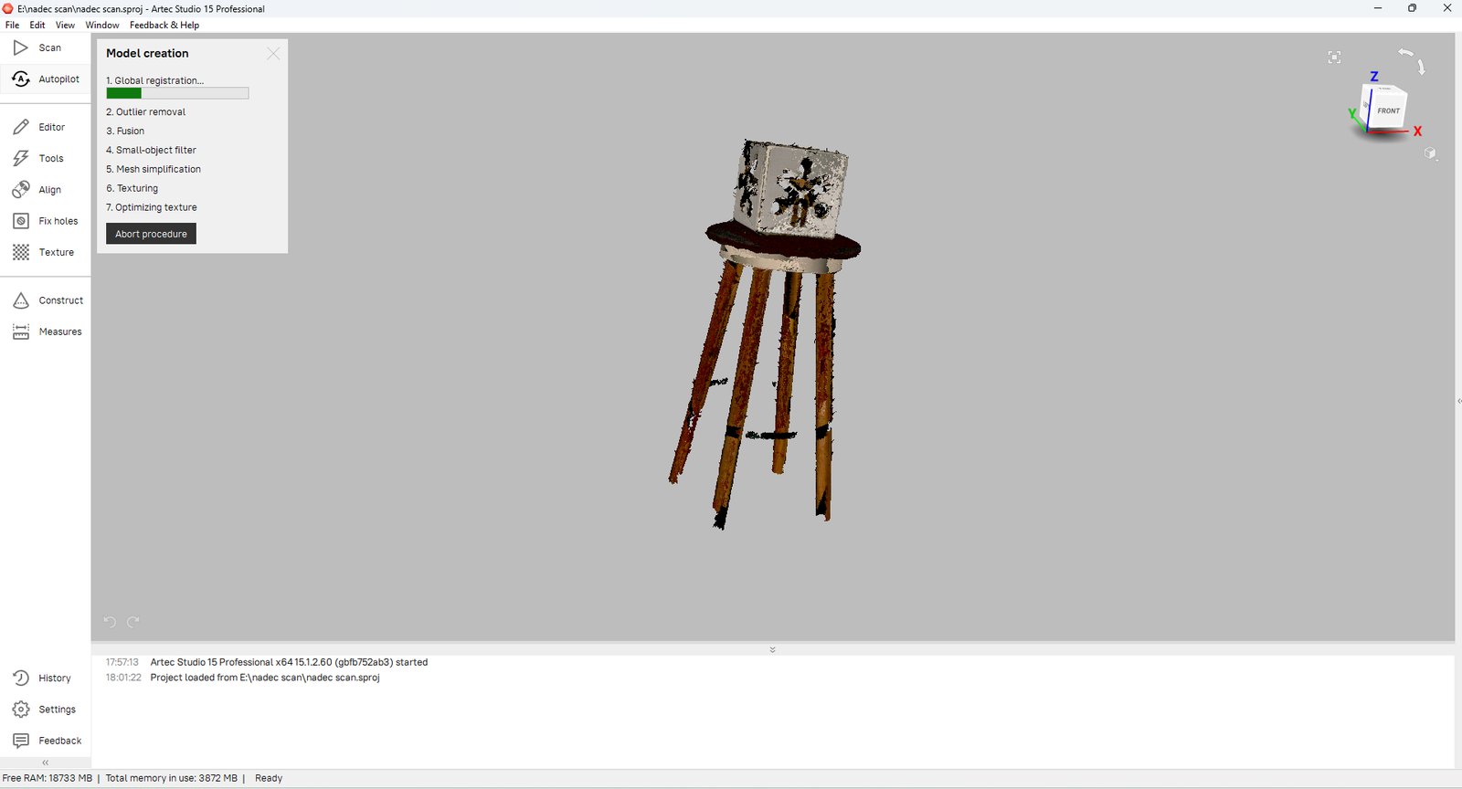
Post-processing in Artec Studio#
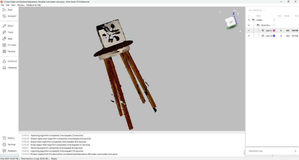
Step 1 — Loaded the project in Artec Studio 15. Two Leo scans sitting in the workspace — Leo 1.1 (361 frames) and Leo 1.2 (413 frames).
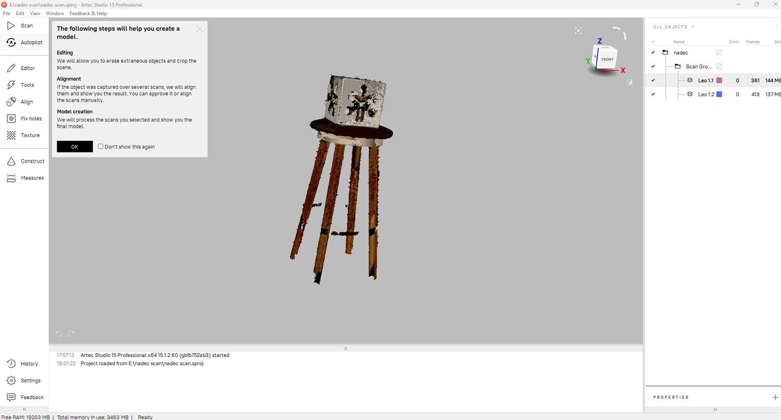
Step 2 — Hit Autopilot. It gave a quick overview of what it’s about to do — editing, alignment, then model creation.
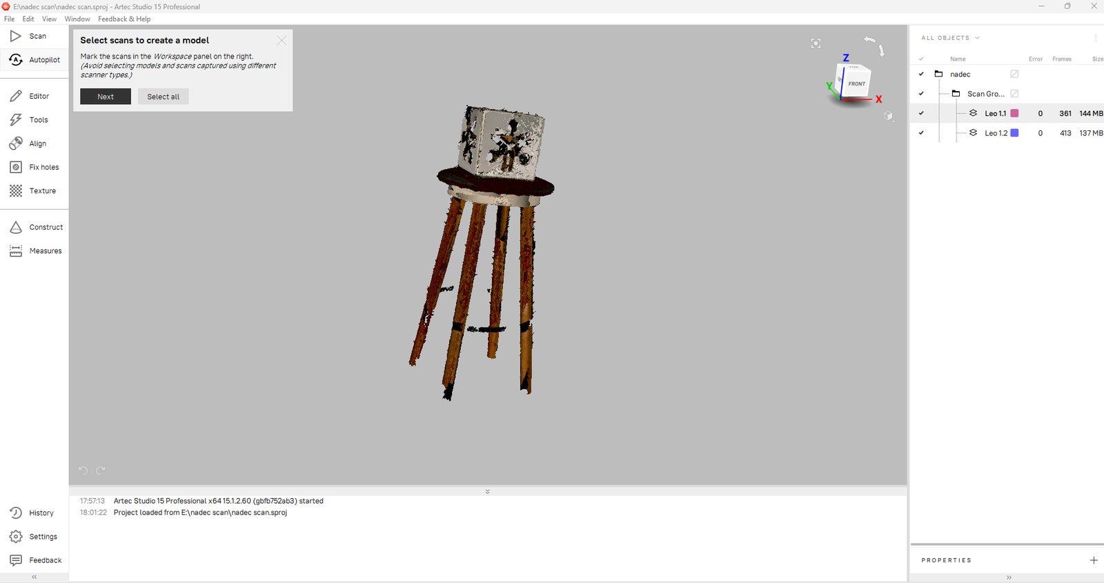
Step 3 — Selected both scans to feed into the model creation pipeline.
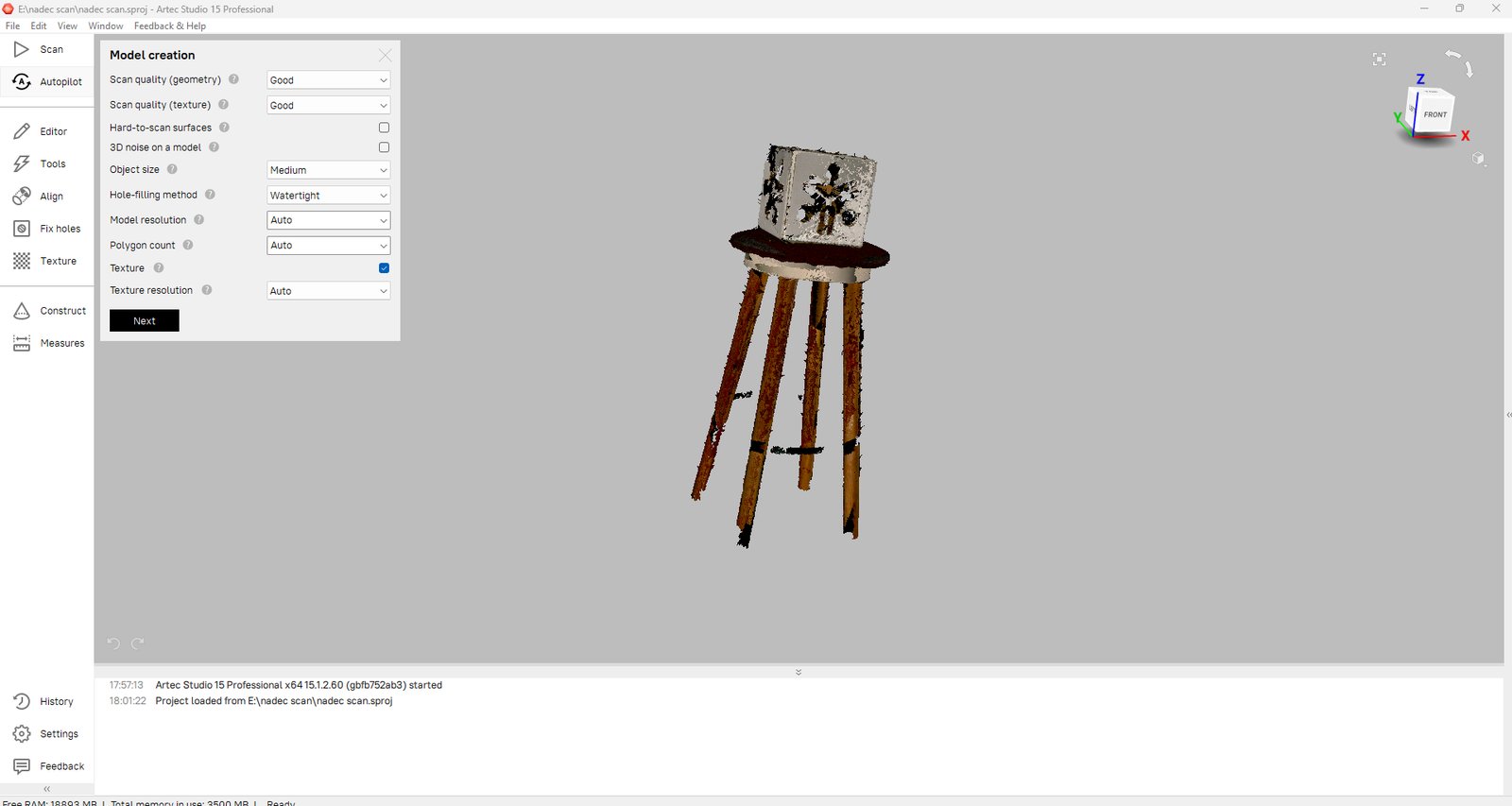
Step 4 — Set the parameters. Quality: Good, size: Medium, hole-filling: Watertight, everything else on Auto. Texture enabled.
Step 5 — Pipeline started. Global Registration running first — aligning all the frames together.
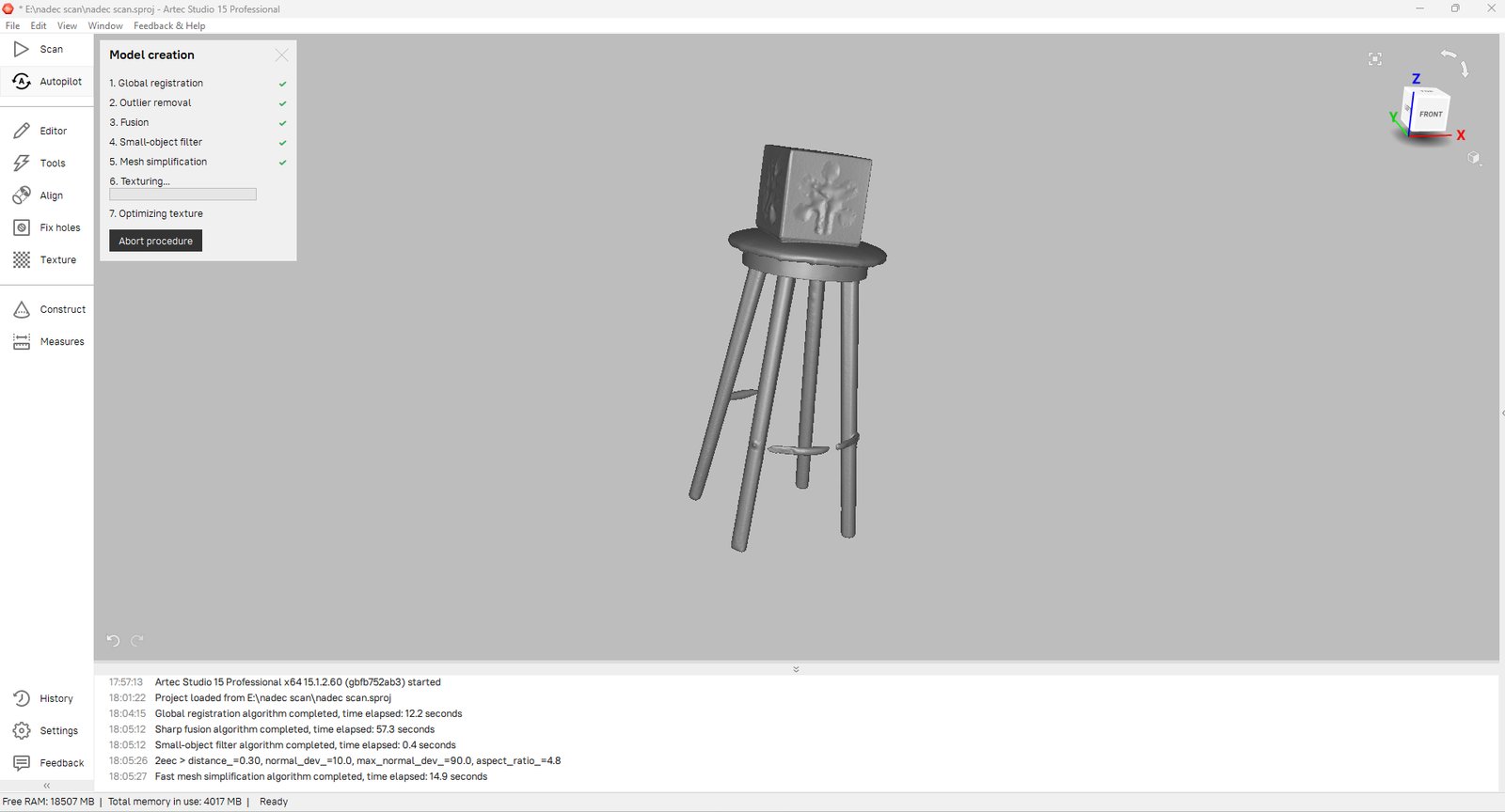
Step 6 — Steps 1–5 done. Texturing in progress, mesh already looking clean in the viewport.
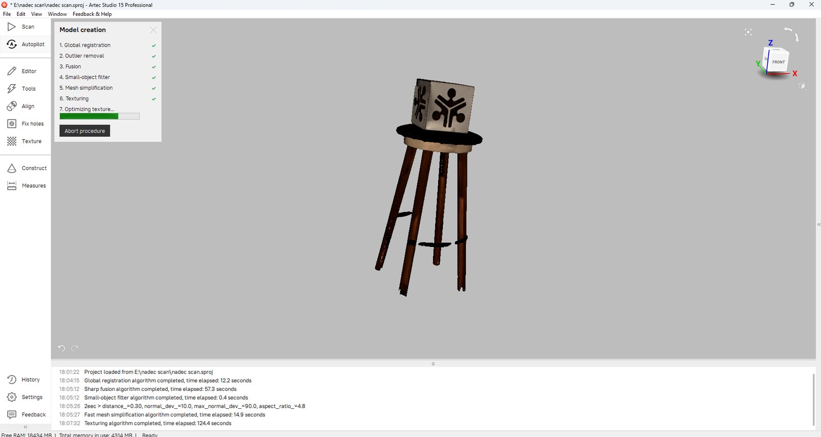
Step 7 — Texturing done (took 124 seconds). Now on the last step — texture optimization.
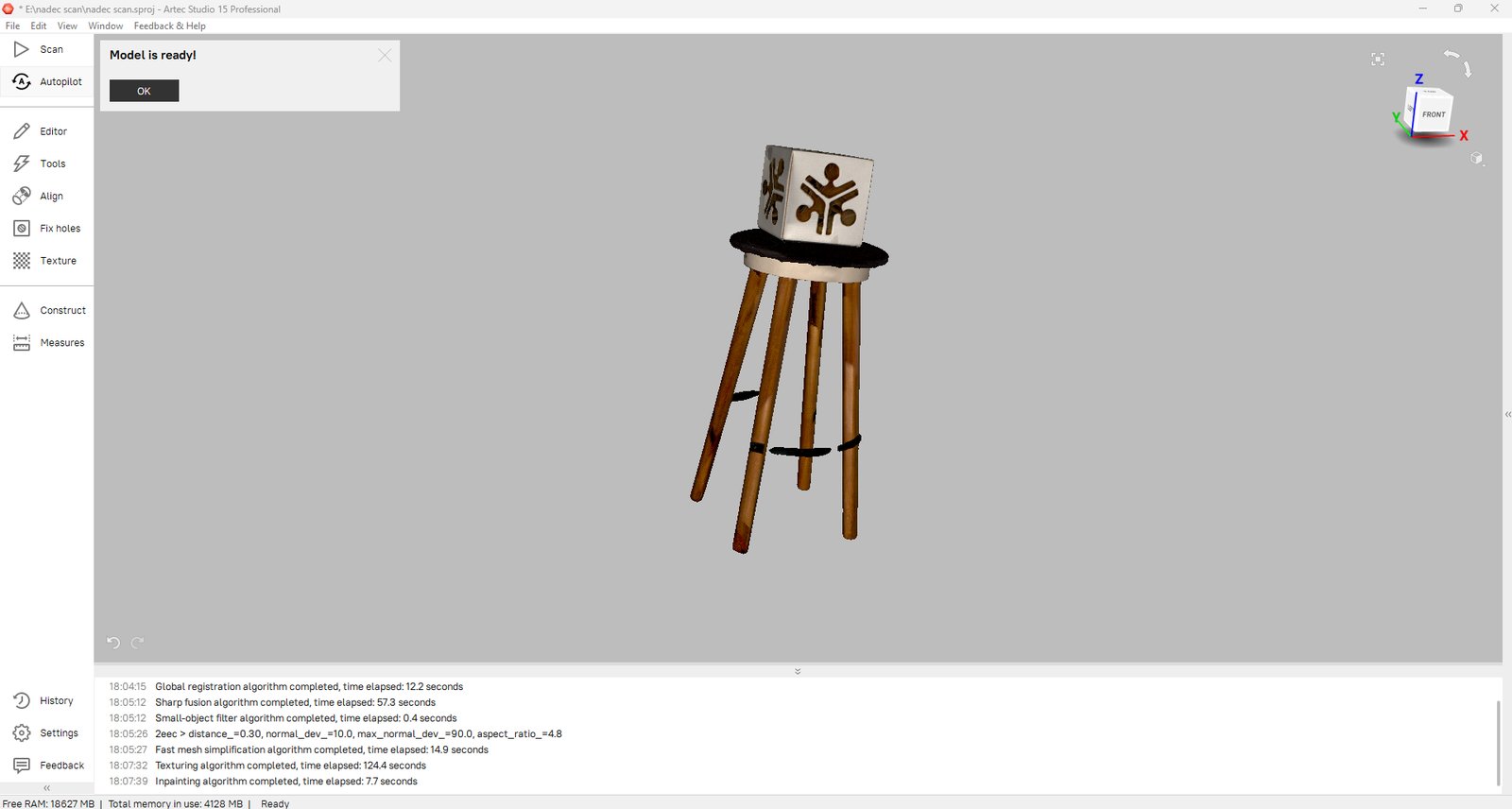
Step 8 — “Model is ready!” All 7 steps done, final textured model looks solid.
Object Scanned#
- Stool
Status#
- Scan complete
- Post-processing pending
Limitations and Observations#
The Leo gave a pretty clean model, but it wasn’t perfect. Surfaces that weren’t smooth, like the stool’s rough seat part, were harder for the scanner to read than flat or curved parts. Those spots needed more passes to clean up, and you could still see extra bumpy noise there compared to the smooth legs.
Shiny surfaces were really annoying. The scanner shoots light at the object to figure out its shape, and shiny stuff bounces that light around weird, so you end up with holes or messed up shapes right where it’s shiniest. Tiny objects had a similar problem: there’s just not enough surface for the scanner to grab good data from, so the small parts came out less detailed than the bigger stool.
Basically: the Leo works great when the object is matte, big enough, and has simple smooth shapes. But it’s not magic. Give it a bad surface and it gives you a bad scan, kind of like taking a photo in bad lighting.
Workflow 2 – Kiri Engine (Mobile)#
Process#
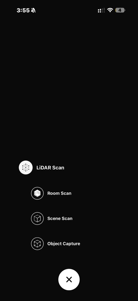
- Opened the app
- Selected New Project
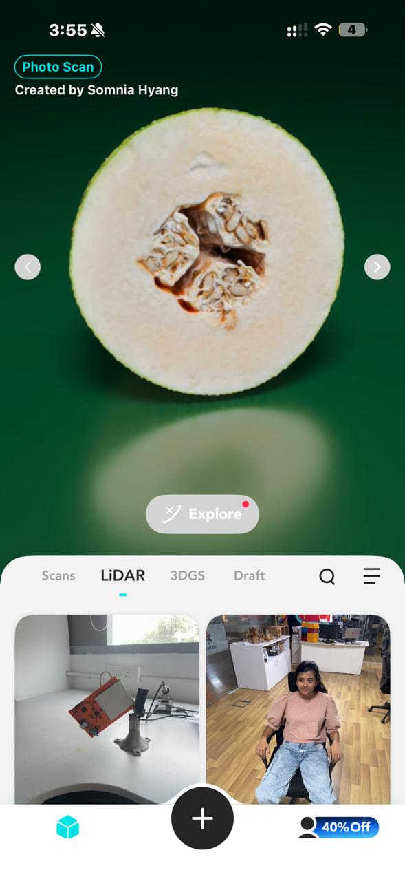
- Selected LiDAR Scan

- Selected Object Scan
- Followed on-screen instructions
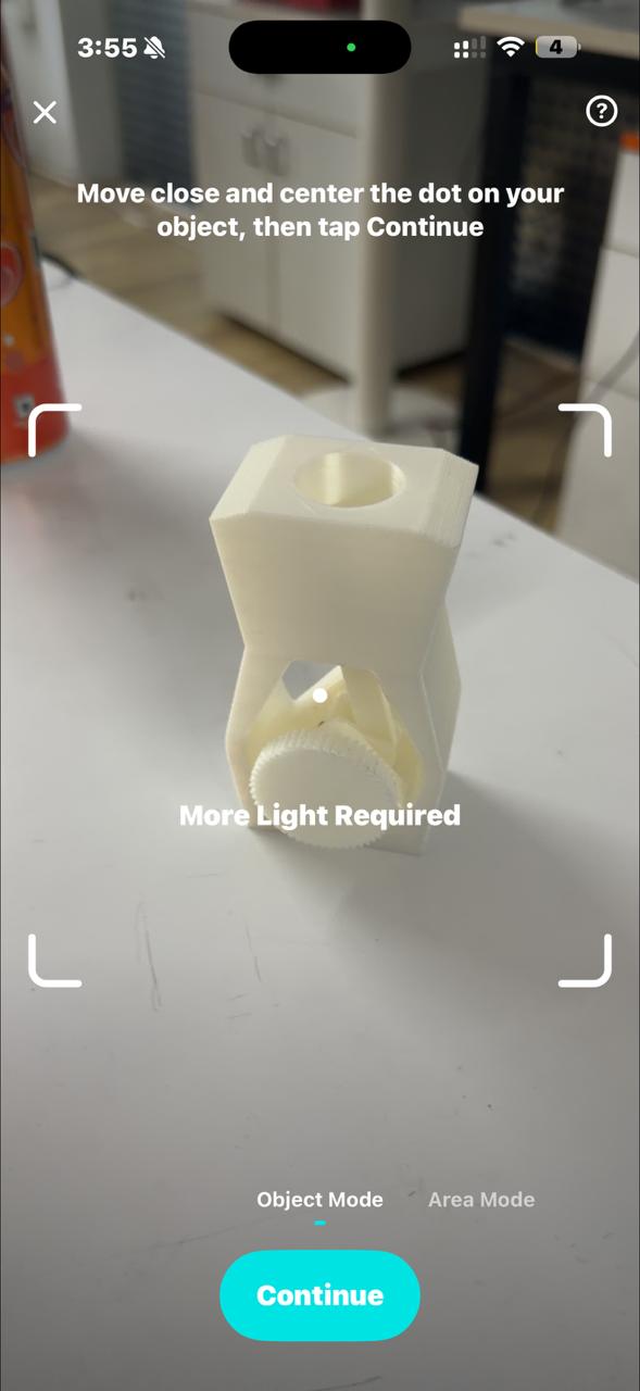
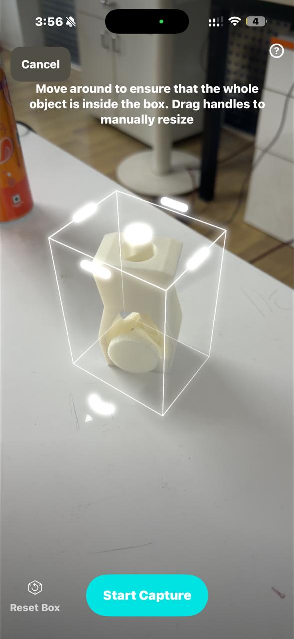
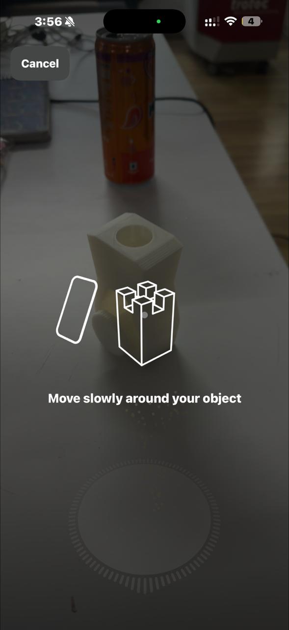
- Completed scan
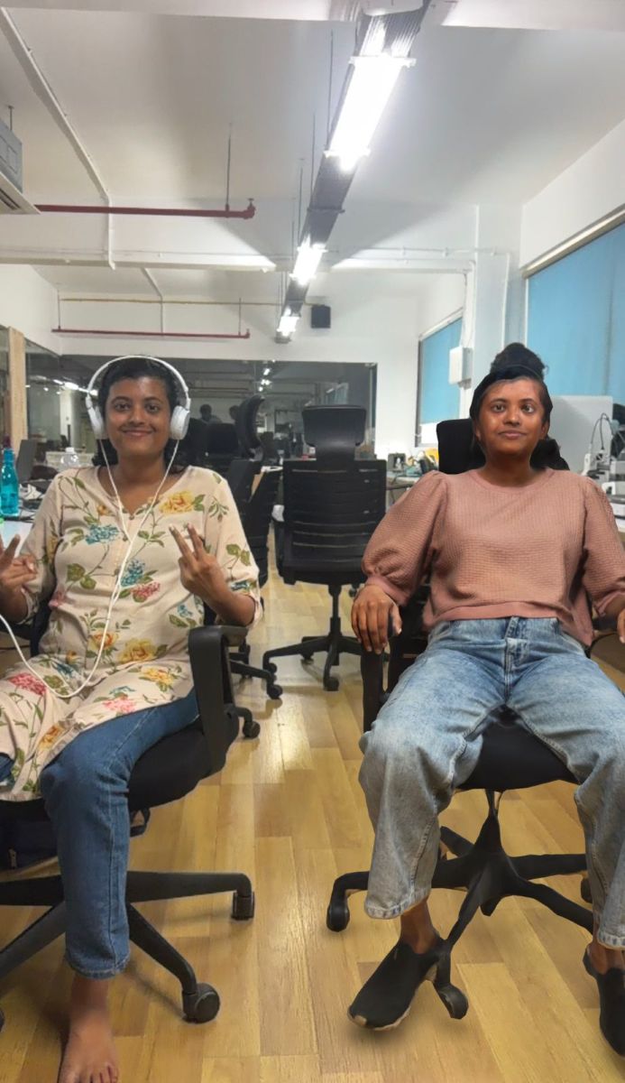
Object / People Scanned#
My classmate Merin https://fabacademy.org/2026/labs/kochi/students/merin-cyriac/
3d printed model of Merin

My Gaming Handheld Device from Week 4
Next Plan#
- Clean the mesh
- Fix artifacts
- 3D print a scaled model
Limitations and Observations#
Kiri Engine had the same rough-surface problem as the Leo. Bumpy or textured spots came out noisier and needed more cleanup. Also, Kiri was way less accurate than the Artec Leo. That makes sense once you think about it: the Leo is a real scanner made just for this job, while Kiri is using a phone’s camera and LiDAR to guess the shape. Less fancy hardware, less accurate result.
Shiny surfaces and tiny objects gave it trouble too, for the same reasons as the Leo. Shiny stuff confuses the sensor, and tiny objects just don’t give it enough to work with.
Artec Leo vs Kiri Engine — Which One Would I Actually Use?#
If we’re only talking about accuracy, the Leo wins easily. But accuracy isn’t the only thing that matters. If I think about how easy it is to get the hardware, how easy it is to use, and how good the accuracy needs to be for most jobs, I’d actually pick Kiri Engine most of the time.
The Leo is expensive scanner equipment that’s stuck in the lab, and you need to learn the Artec Studio software to get good results out of it. Kiri Engine is just an app on the phone I already carry around. Yeah, it’s less accurate, but for most jobs, like getting a rough model to clean up and print, that’s totally fine. The Leo is the better choice when you really need scan-level accuracy. For everything else, the phone in my pocket beats a fancy scanner I have to go track down and learn.
Reflection#
This week felt like a shift from just designing things to actually manufacturing intelligently.
Coming from a strong CAD background, I initially thought this week would be easy — but I quickly realized that 3D printing introduces a completely new layer of complexity. A model that looks perfect in CAD can completely fail during printing if design rules and machine limitations are not considered.
What stood out to me the most was how real-world constraints dominate the outcome:
- orientation affects strength and surface finish
- supports affect both print success and post-processing
- small parameter changes can completely change the result
3D scanning was also an eye-opener. I expected clean models directly, but in reality, the process is messy and requires multiple iterations and cleanup. It made me appreciate how imperfect real-world data is compared to CAD models.
One thing I did well this week was experimenting beyond just the assignment. Instead of making something basic, I explored workflows and pushed towards more interesting outputs, which aligns more with how I like to work.
If I had more time, I would:
- experiment more with different materials (PLA, PETG, etc.)
- optimize prints for strength vs speed
- explore higher-quality scanning workflows (LiDAR vs photogrammetry)
Overall, this week strengthened my understanding that:
Designing is only half the job — manufacturing constraints define the final result.
This directly connects to my long-term goal of building automated fabrication workflows, where design → slicing → printing can be streamlined with minimal manual intervention.