Week 10 - Output Devices#
Week 10 was all about output devices, the flip side of last week. If Week 9 was about sensing the world, this week was about acting on it. Motors, drivers, power management, and actually making something move.
The assignment: design a board with an output device, then program it to do something.
Group Assignment#
- Measure the power consumption of an output device
Individual Assignment#
- Add an output device to a microcontroller board you’ve designed, and program it to do something
Extra Credit Goals
- Try multiple output types
- Implement PWM control or other modulation techniques
What I Learned#
Software Used#
- KiCad: schematic + PCB layout
- Arduino IDE: firmware
- Mods CE: CAM for PCB milling
- Browser + Git: documentation
Weekly Schedule#
| Day | What I Did |
|---|---|
| WED | Lecture on output devices |
| THU | Group Assignment, power measurement |
| FRI | Selecting output devices, reading ESP32-WROOM-32E datasheet |
| SAT | DRV8825 datasheet deep-dive, schematic design in KiCad |
| SUN | PCB layout, single DRV design |
| MON | Milling, soldering, testing |
| TUE | Regional review |
Group Assignment#
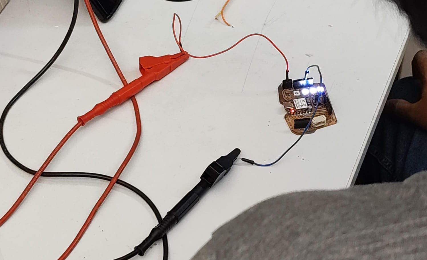
For this group assignment, we measured power consumption hands-on instead of just trusting the numbers in a datasheet. We hooked up a bench power supply and a digital multimeter to a couple of output devices and read off the actual current they pulled while running.
The math behind it is simple Ohm’s law territory:
Power (W) = Voltage (V) × Current (A)
NeoPixel:
| Measurement | Value |
|---|---|
| Supply Voltage | 5 V |
| Measured Current | 0.0337 A |
| Power | 5 × 0.0337 = 0.1685 W |
Stepper motor:
| Measurement | Value |
|---|---|
| Supply Voltage | 5 V |
| Measured Current | 0.011 A |
| Power | 5 × 0.011 = 0.055 W |
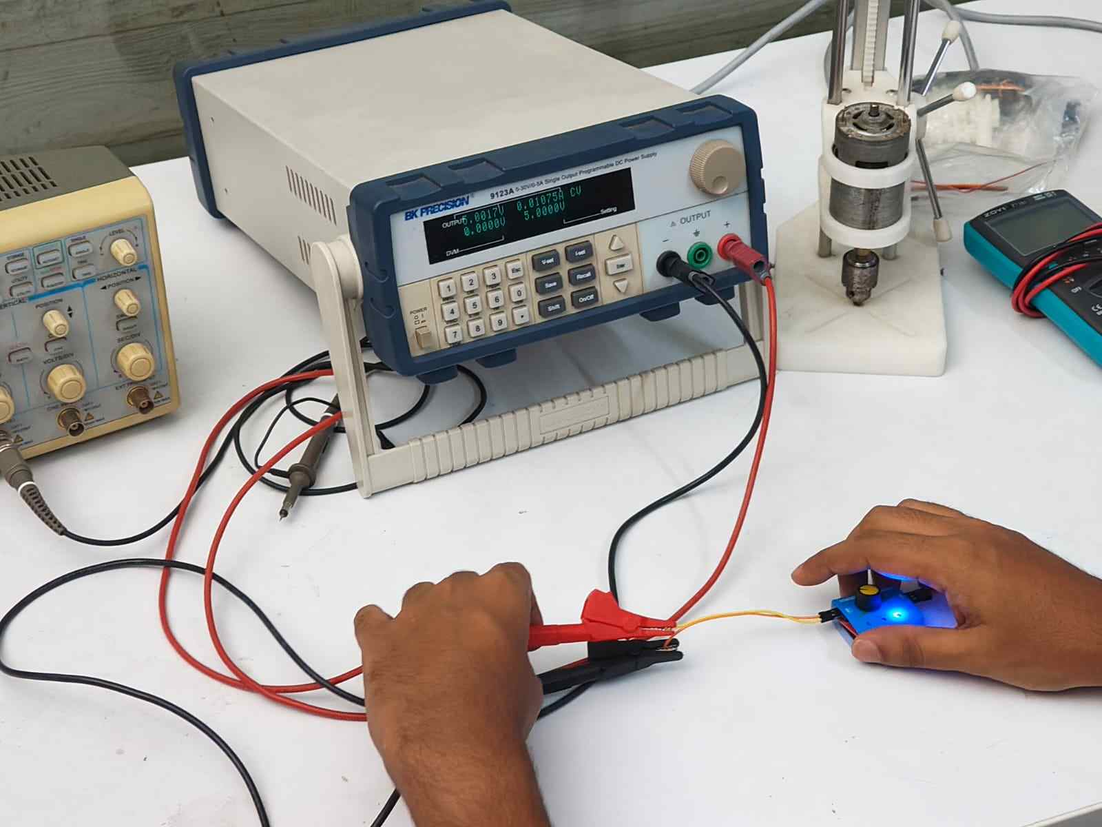
The main thing I took from this is how to hook a multimeter in series to get a real current reading, and how that one number turns into a power figure once you multiply it by the voltage. Knowing the actual draw of a part, not just the datasheet guess, matters a lot when you’re picking a battery or sizing a power supply for an embedded project. Get it wrong and you either run out of juice fast or carry around a way bigger battery than you need.
Source: https://fabacademy.org/2026/labs/kochi/group_assignmetns/week10/
Individual Assignment#
Output Device Selection#
This week’s goal was to build a stepper motor tester. I got the idea from my instructor Sibin K S . He told me that servo testers already exist, little tools that let you check if a servo works without hooking it up to a microcontroller, running jumper wires, and writing Arduino code just to find out if it’s dead. We didn’t have anything like that at our lab for stepper motors. So he suggested building a stepper motor tester that could do the same job: quickly check if a stepper motor works, with no microcontroller wiring or code needed on the spot.
For a future version, I’m planning to add an INA219 chip so I can graph things like current draw versus RPM on a web app.
The stack I landed on:
| Component | Part |
|---|---|
| Microcontroller | ESP32-WROOM-32E |
| Motor driver | DRV8825 |
| Motor | NEMA 17 bipolar stepper |
I picked the ESP32-WROOM-32E because it has WiFi, which means I could control the stepper motor wirelessly down the road, and it has plenty of GPIO pins to run more than one DRV8825 driver if I want to grow this project later. I picked the DRV8825 because it’s a well-known stepper motor driver that can handle what a NEMA 17 motor needs, and it has microstepping built in. I picked the NEMA 17 motor because it’s a common size for hobby projects and gives a good mix of torque and speed for testing.
The Components#
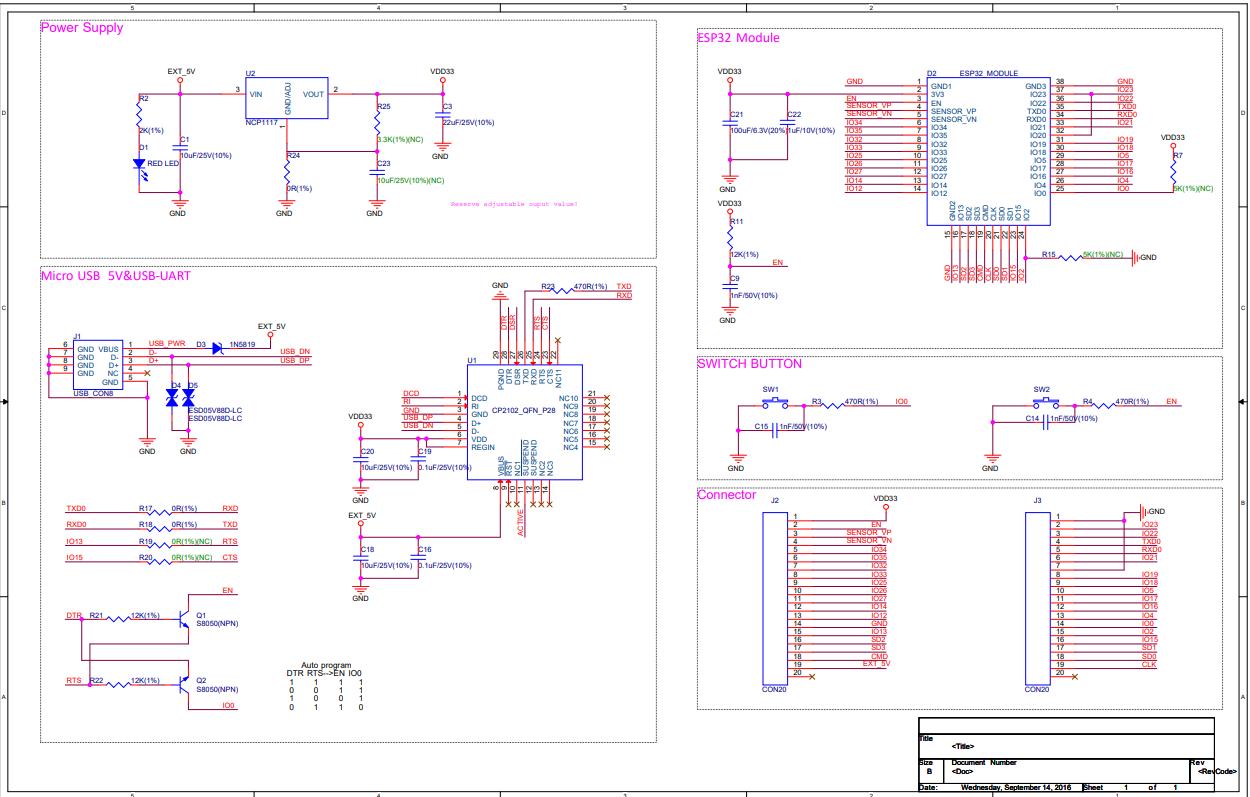
ESP32-WROOM-32E — Microcontroller Module#
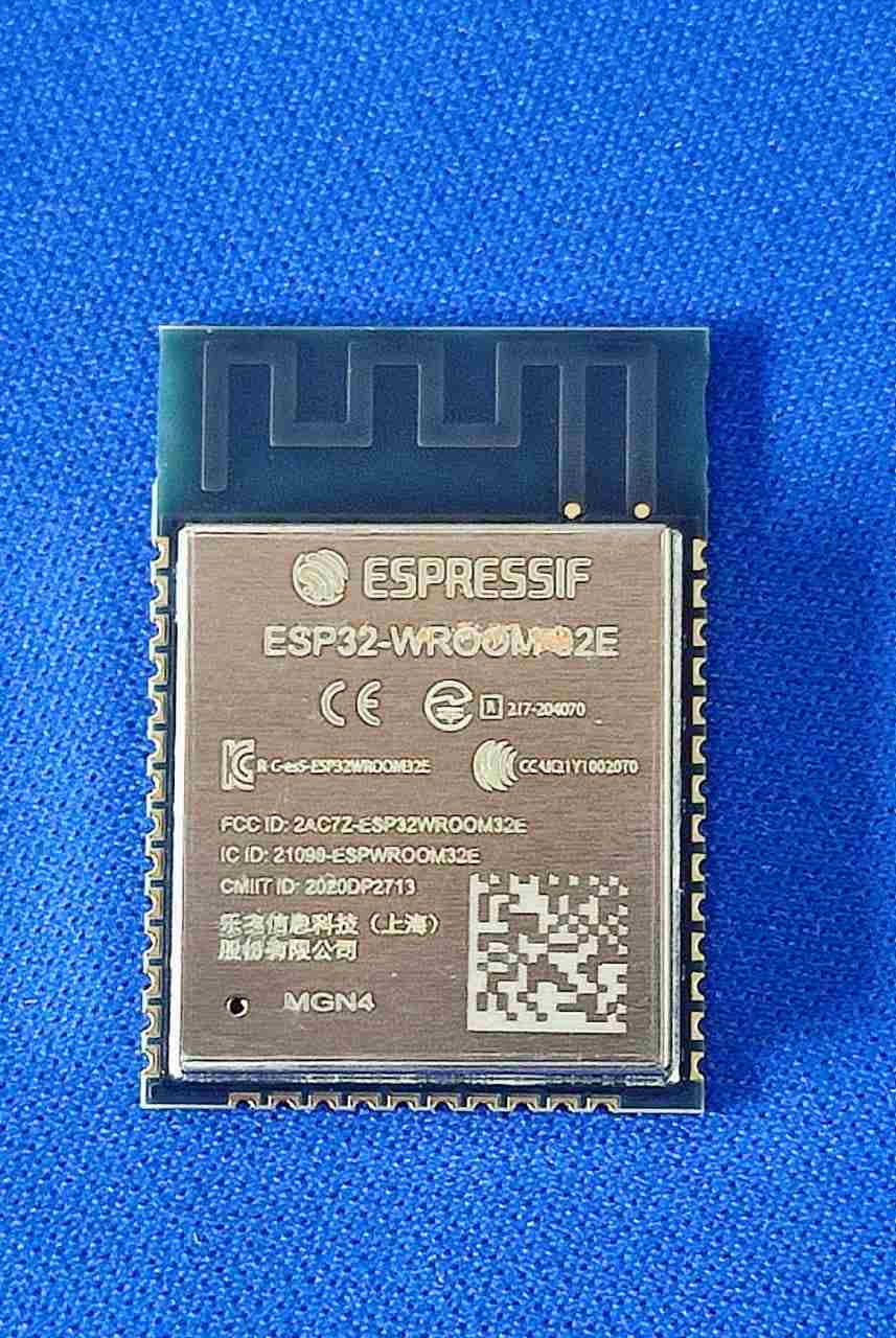
The ESP32-WROOM-32E is a surface-mount WiFi + Bluetooth module from Espressif, built around the ESP32-D0WD-V3 chip. I picked it over the XIAO or ATtiny for a few reasons:
- It has enough GPIO to run five DRV8825 drivers at once (STEP, DIR, ENABLE per driver means 15 pins minimum). For me this was relevant as i wanted to built a wroom based board in the future to control five stepper motors at once, for a future project . Shhh…….
- Built-in WiFi gives me wireless control options for the final project
- It has a strong Arduino/ESP-IDF ecosystem, with libraries for almost everything
- It’s likely what the final project will use anyway, so this week doubles as practice
Key specs:
| Parameter | Value |
|---|---|
| CPU | Xtensa dual-core LX6, up to 240 MHz |
| Flash | 4 MB (on-module) |
| RAM | 520 KB SRAM |
| WiFi | 802.11 b/g/n (2.4 GHz) |
| Bluetooth | BT 4.2 + BLE |
| GPIO | 38 pins |
| ADC | 18 channels, 12-bit |
| PWM | Ledc peripheral — 16 channels |
| Supply voltage | 3.0 – 3.6 V (module) |
| Programming | USB-UART bridge + EN/IO0 boot pins |
The above specs are found from the ESP32-WROOM-32E datasheet and curated using Claude by Anthropic.
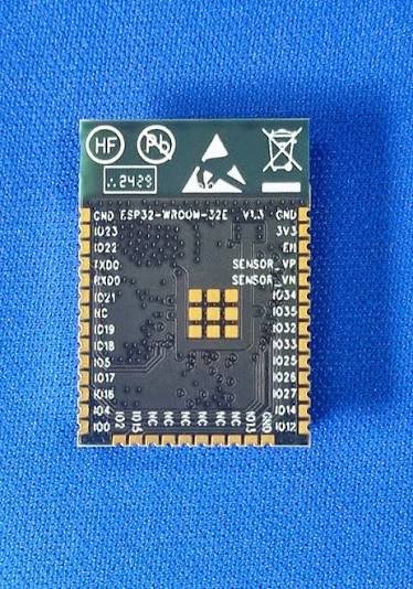
Minimum circuit:
I went through the ESP32-WROOM-32E datasheet properly, not just the pinout but the application circuit section too. The minimum circuit needs:
- 3.3 V regulated supply with bulk and bypass decoupling (100 µF + 100 nF on VDD)
- EN pin pulled HIGH through a 10 kΩ resistor (the module won’t boot if EN is left floating)
- IO0 pin pulled HIGH through a 10 kΩ resistor for normal boot, or pulled LOW to enter download mode
- UART0 (TX = GPIO1, RX = GPIO3) brought out for programming through a USB-UART bridge (CP2102 or CH340)
- Boot button on IO0 and a Reset button on EN, both needed for programming to work reliably
This is the stuff that gets skipped when you use a ready-made dev board. Building it from scratch forces you to actually understand what the chip needs to run.
DRV8825 — Stepper Motor Driver#
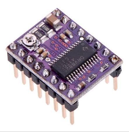
The DRV8825 is a bipolar stepper motor driver IC from Texas Instruments. It handles all the H-bridge switching on its own. You just send STEP pulses and a DIR signal from the microcontroller, and the IC drives the motor coils at whatever current you’ve set.
Key specs:
| Parameter | Value |
|---|---|
| Motor supply voltage | 8.2 – 45 V |
| Output current | Up to 2.5 A per coil (with heatsink) |
| Microstepping | Full, 1/2, 1/4, 1/8, 1/16, 1/32 |
| Logic supply | 3.3 V / 5 V compatible |
| Interface | STEP / DIR / ENABLE |
| Thermal shutdown | Yes |
| Overcurrent protection | Yes |
The above specs are found from the DRV8825 datasheet and curated using Claude by Anthropic.
How it works:
The DRV8825 has two H-bridge outputs, one for each motor coil (coil A and coil B). Each H-bridge can push and pull current, which is exactly what bipolar stepper control needs. You set the current limit by turning a potentiometer on the VREF pin.
The microstepping resolution is set with three pins: MODE0, MODE1, MODE2. Setting them LOW or HIGH in different combinations selects anything from full-step to 1/32 step.
Pin connections from datasheet:
| Pin | Function |
|---|---|
| VMOT | Motor power supply (8.2–45 V) — 100 µF cap mandatory here |
| GND | Power ground |
| VDD | Logic supply (3.3 V) |
| STEP | Step pulse input — one rising edge = one step |
| DIR | Direction — HIGH/LOW sets rotation direction |
| ENABLE | Active LOW — pull LOW to enable outputs |
| MODE0/1/2 | Microstepping select |
| FAULT | Active LOW fault output (overcurrent, thermal) |
| RESET | Active LOW reset — pull HIGH for normal operation |
| SLEEP | Active LOW sleep — pull HIGH for normal operation |
| B2, B1 | Coil B outputs |
| A2, A1 | Coil A outputs |
⚠️ The 100 µF capacitor on VMOT is not optional. The DRV8825 datasheet says so directly. When the motor slows down, it acts like a generator and pushes current back into VMOT. Without the cap, that voltage spike can go past the driver’s absolute maximum rating and kill the IC instantly. (I’m using a 470uf cap on my board, just to be safe.)
NEMA 17 — Bipolar Stepper Motor#
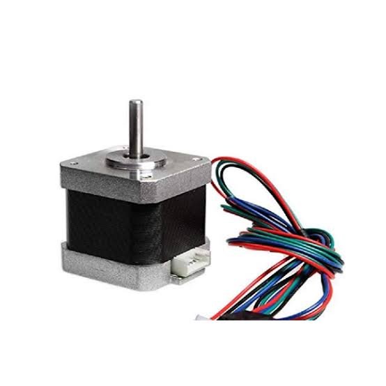
What is a stepper motor?
A stepper motor is a brushless DC motor that splits a full rotation into a fixed number of steps. A regular DC motor just spins when you give it voltage, but a stepper motor moves in small, repeatable steps, which makes it great for position control without needing a feedback sensor.
Types of stepper motors:
| Type | Description | Wires |
|---|---|---|
| Unipolar | Has a center tap on each coil — simpler driver circuit, lower torque | 5 or 6 wires |
| Bipolar | No center tap — both coil ends driven by the driver, higher torque, needs H-bridge | 4 wires |
| Variable reluctance | Uses soft iron rotor, no permanent magnets — fast but low torque | — |
| Hybrid | Most common — combines permanent magnet + toothed rotor for high resolution | 4 wires |
Why NEMA 17?
NEMA 17 is just a mechanical frame standard. It sets the faceplate size (42.3 × 42.3 mm, 4 mounting holes on a 31 mm bolt circle), not the motor’s electrical specs. But in practice, NEMA 17 motors are almost always bipolar hybrid steppers, and that combination is what made it the right pick:
- 1.8° per step (200 steps per revolution), a standard resolution that works well with DRV8825 microstepping
- High torque-to-size ratio, enough torque for most mechanical jobs without jumping up to a bulkier NEMA 23
- Widely available, cheap, well-documented, with a huge ecosystem of mounts, pulleys, and couplers
- 4-wire bipolar, which plugs straight into the DRV8825 with no center tap to worry about
The four wires — coil identification:
A bipolar NEMA 17 has four wires that make up two coils:
| Wire | Label | Function |
|---|---|---|
| Coil A+ | A1 | One end of coil A |
| Coil A− | A2 | Other end of coil A |
| Coil B+ | B1 | One end of coil B |
| Coil B− | B2 | Other end of coil B |
The driver fires coil A and coil B in sequence, and the pull between the rotor magnets and the energized coils drags the rotor into each new step position. Direction is set by reversing the order the coils are fired in, which is exactly what the DIR pin on the DRV8825 controls.
To figure out which wires belong to the same coil, I used a multimeter set to continuity or resistance mode. Wire pairs with low resistance (around 1–5 Ω) are the same coil. Pairs with no continuity belong to different coils.
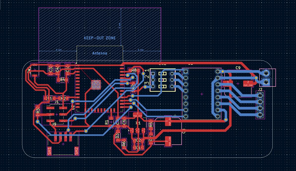
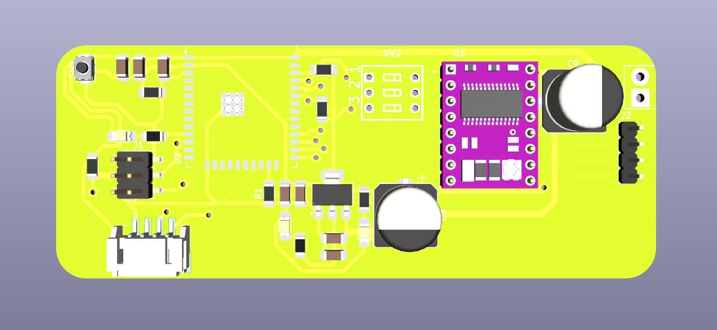
Board Design#
Once I understood all my parts and how they worked, I moved on to actually designing the board. I used KiCad to draw the schematic, lay out the PCB, and check the 3D model before sending it off to be milled.
Schematic#
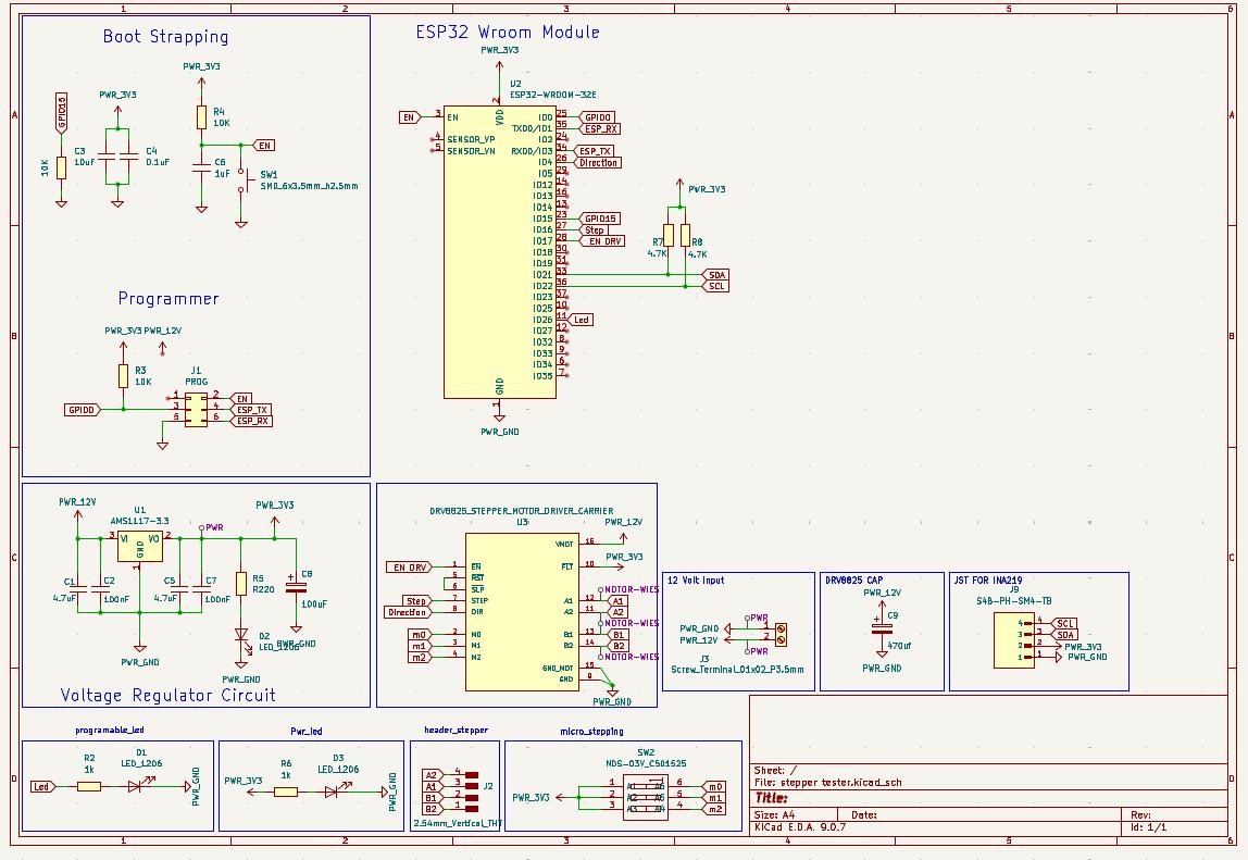
PCB Layout#
3D View#
Manufacturing#
- Milling machine: Carvera
- Substrate: FR1 double-sided copper clad
- Trace width / clearance: 0.6 mm / 0.4 mm (logic), 1.1 mm (motor power traces)
- Tool: 0.2 mm 60° V-bit (traces), 1/32" flat end mill (outline)
- Software: Mods CE
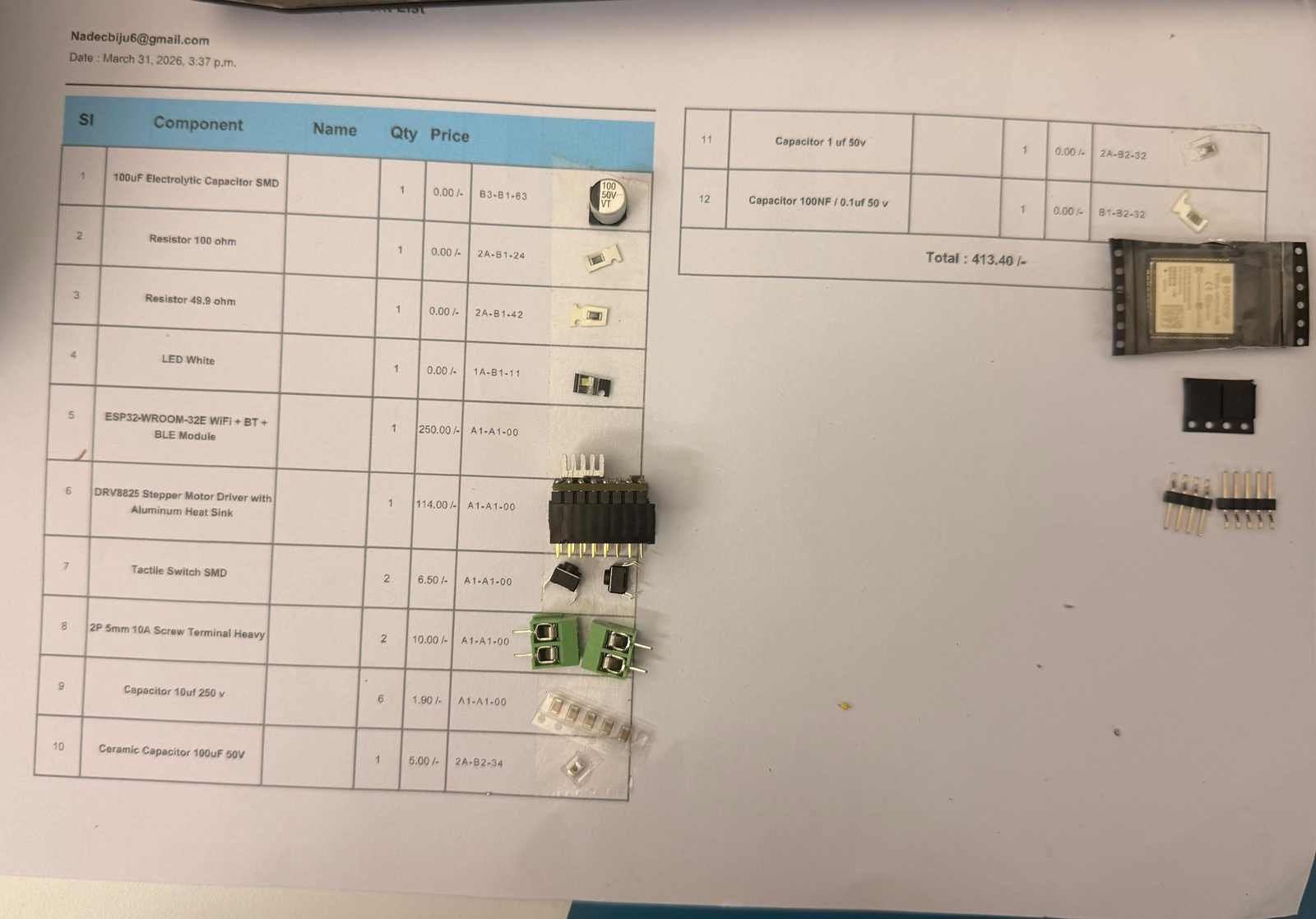
Bill of Materials:
| Component | Value | Qty |
|---|---|---|
| C1, C5 | 4.7uF | 2 |
| C2, C4, C7 | 0.1uF | 3 |
| C3 | 10uF | 1 |
| C6 | 1uF | 1 |
| C8 | 100uF | 1 |
| D1, D2, D3 | LED | 3 |
| J1 | PROG header (2x03) | 1 |
| J2 | 1x04 header | 1 |
| J3 | Screw terminal 1x02 | 1 |
| R1, R3, R4 | 10K | 3 |
| R2, R6 | 1k | 2 |
| R5 | R220 | 1 |
| R7, R8 | 4.7K | 2 |
| SW1 | Push button | 1 |
| SW2 | NDS-03V switch | 1 |
| U1 | AMS1117-3.3 | 1 |
| U2 | ESP32-WROOM-32E | 1 |
| U3 | DRV8825 carrier | 1 |
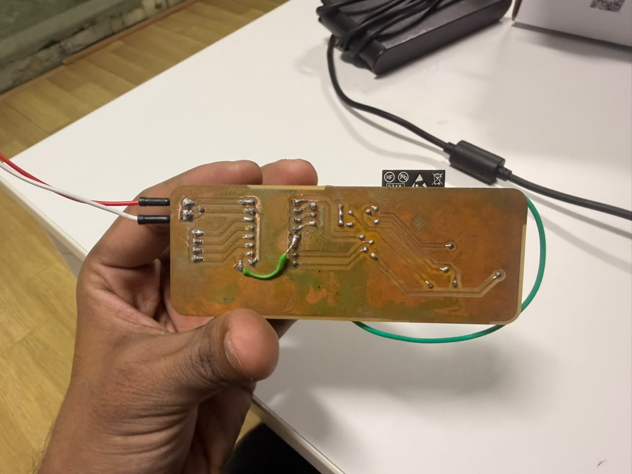
Soldered PCB#
Then i went ahead and sourced thecomponents required for the board and soldered them on the board. The soldering was done using a hot air rework station and a soldering iron. The final result was a cleanly soldered board with all components in place.
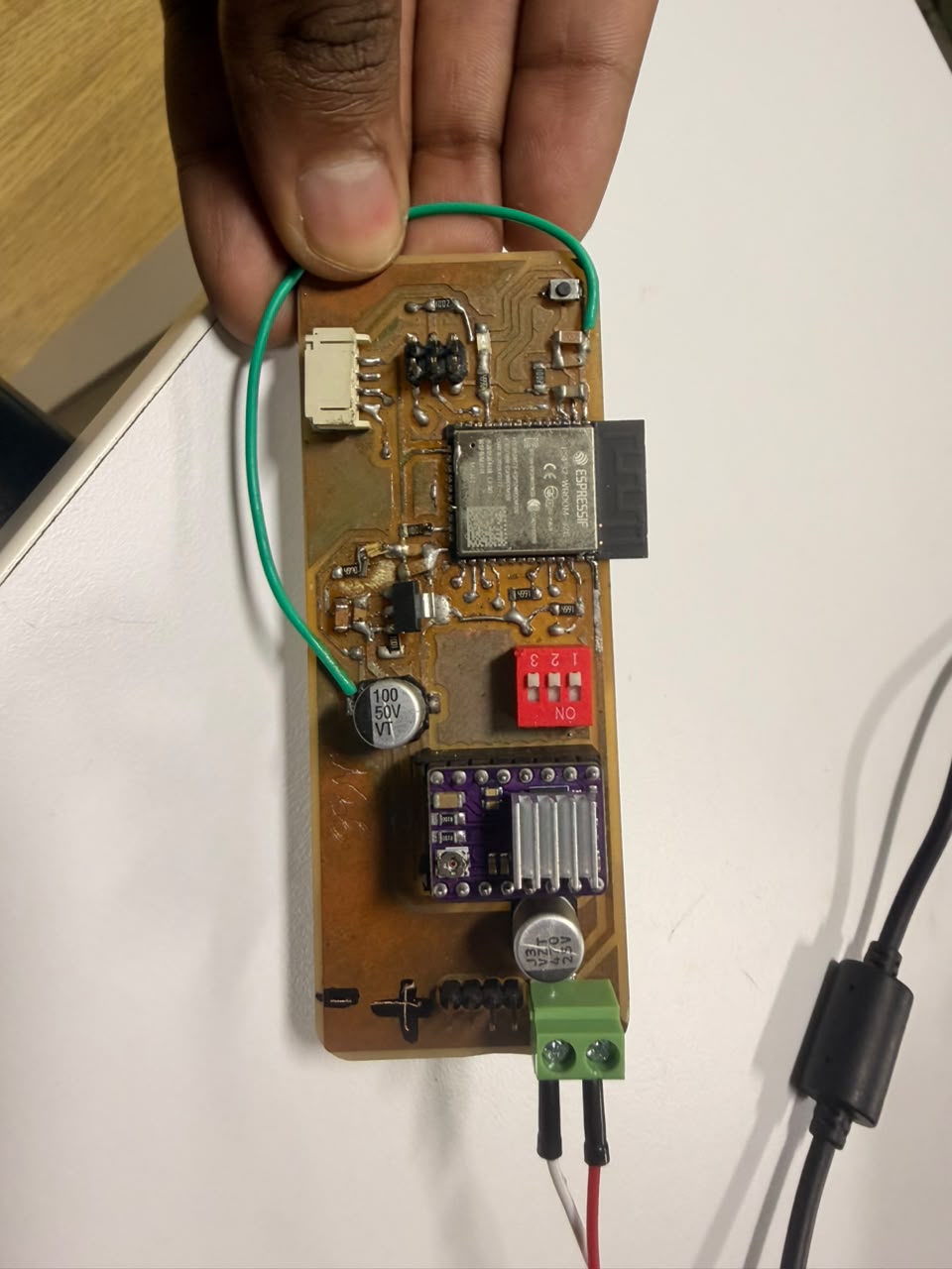
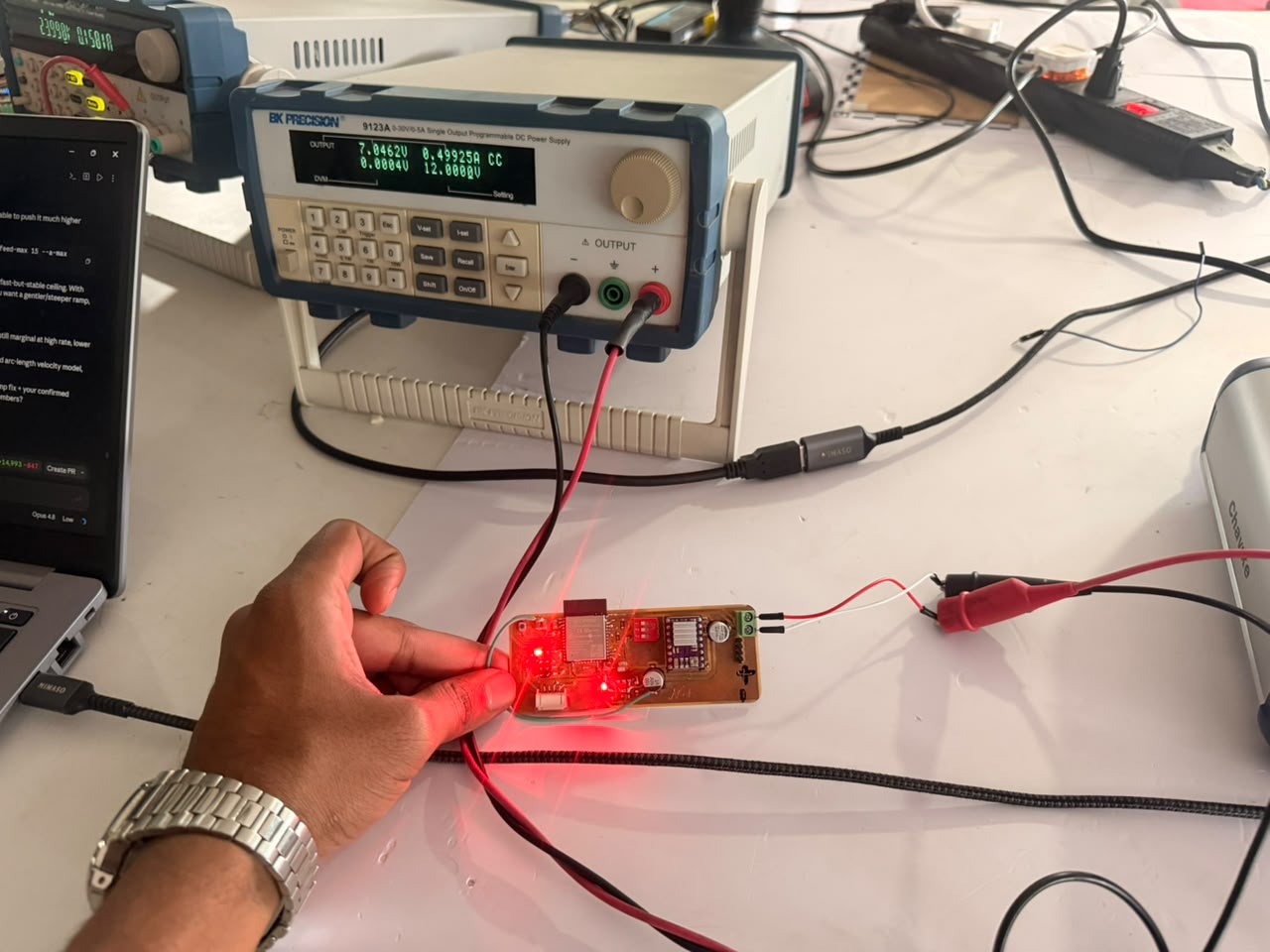
Testing the Board#
After soldering the board, I went ahead and tested the board by connecting it to a stepper motor and running some test code.
Code#
/*
* Stepper Motor Tester - ESP32-WROOM-32E + DRV8825
*
* Pinout:
* GPIO4 -> DRV8825 DIR
* GPIO16 -> DRV8825 STEP
* GPIO17 -> DRV8825 EN (active LOW)
*
* M0/M1/M2 are wired to an external DIP switch (3V3 or GND), not to the
* ESP32, so firmware cannot read or set the microstep mode. The web UI
* lets the user enter the DIP switch state and computes steps/rev from
* the DRV8825 truth table.
*
* Connect to the open WiFi AP "StepperTester" - no password. A captive
* portal redirect takes you straight to the control page.
*/
#include <WiFi.h>
#include <WebServer.h>
#include <DNSServer.h>
#define DIR_PIN 4
#define STEP_PIN 16
#define EN_PIN 17
#define LED_PIN 26
#define DEFAULT_STEPS_PER_REV 200
#define MIN_STEP_HIGH_US 2
#define MIN_RPM 1
#define MAX_RPM 300
#define MAX_STEPS 100000
#define LED_IDLE_PERIOD_MS 1000
#define LED_BUSY_PERIOD_MS 80
#define STATUS_PRINT_PERIOD_MS 3000
const char *AP_SSID = "StepperTester";
const IPAddress AP_IP(192, 168, 4, 1);
DNSServer dnsServer;
WebServer server(80);
bool driverEnabled = false;
volatile bool busy = false;
unsigned long ledLastToggle = 0;
bool ledState = false;
unsigned long statusLastPrint = 0;
void setEnabled(bool en) {
driverEnabled = en;
digitalWrite(EN_PIN, en ? LOW : HIGH);
Serial.print("Driver: ");
Serial.println(en ? "ENABLED" : "disabled");
}
// Periodic heartbeat over Serial: WiFi AP state + driver/motor state
void printStatusLine() {
Serial.print("[status] WiFi AP: ");
Serial.print(WiFi.softAPgetStationNum());
Serial.print(" client(s) connected, IP=");
Serial.print(WiFi.softAPIP());
Serial.print(" | Driver: ");
Serial.print(driverEnabled ? "ENABLED" : "disabled");
Serial.print(" | Motor: ");
Serial.println(busy ? "MOVING" : "idle");
}
void updateStatusPrint() {
unsigned long now = millis();
if (now - statusLastPrint >= STATUS_PRINT_PERIOD_MS) {
statusLastPrint = now;
printStatusLine();
}
}
// Slow heartbeat blink while idle - called from loop()
void updateIdleLed() {
unsigned long now = millis();
if (now - ledLastToggle >= LED_IDLE_PERIOD_MS) {
ledLastToggle = now;
ledState = !ledState;
digitalWrite(LED_PIN, ledState);
}
}
unsigned long computeStepDelayUs(int rpm, int stepsPerRev) {
unsigned long delayUs = 30000000UL / ((unsigned long)rpm * stepsPerRev);
if (delayUs < MIN_STEP_HIGH_US) delayUs = MIN_STEP_HIGH_US;
return delayUs;
}
void runSteps(long steps, bool cw, int rpm, int stepsPerRev) {
setEnabled(true);
digitalWrite(DIR_PIN, cw ? HIGH : LOW);
unsigned long d = computeStepDelayUs(rpm, stepsPerRev);
Serial.print("Motor: MOVING ");
Serial.print(steps);
Serial.print(" steps ");
Serial.print(cw ? "CW" : "CCW");
Serial.print(" @ ");
Serial.print(rpm);
Serial.print(" RPM (spr=");
Serial.print(stepsPerRev);
Serial.println(")");
unsigned long ledLast = millis();
bool fastLedState = false;
for (long i = 0; i < steps; i++) {
digitalWrite(STEP_PIN, HIGH);
delayMicroseconds(d);
digitalWrite(STEP_PIN, LOW);
delayMicroseconds(d);
if (i % 1000 == 0) yield();
unsigned long now = millis();
if (now - ledLast >= LED_BUSY_PERIOD_MS) {
ledLast = now;
fastLedState = !fastLedState;
digitalWrite(LED_PIN, fastLedState);
}
}
// hand the LED back to the idle heartbeat in loop()
digitalWrite(LED_PIN, LOW);
ledState = false;
ledLastToggle = millis();
Serial.println("Motor: idle");
}
int clampInt(long v, int lo, int hi) {
if (v < lo) return lo;
if (v > hi) return hi;
return (int)v;
}
int paramSpr() {
if (!server.hasArg("spr")) return DEFAULT_STEPS_PER_REV;
long spr = server.arg("spr").toInt();
if (spr <= 0) return DEFAULT_STEPS_PER_REV;
return (int)spr;
}
void handleRun() {
if (busy) {
server.send(409, "application/json", "{\"status\":\"busy\"}");
return;
}
long steps = server.hasArg("steps") ? server.arg("steps").toInt() : 200;
steps = clampInt(steps, 1, MAX_STEPS);
bool cw = server.arg("dir") != "ccw";
int rpm = server.hasArg("rpm") ? server.arg("rpm").toInt() : 60;
rpm = clampInt(rpm, MIN_RPM, MAX_RPM);
int spr = paramSpr();
busy = true;
runSteps(steps, cw, rpm, spr);
busy = false;
String json = "{\"status\":\"ok\",\"steps\":" + String(steps) +
",\"dir\":\"" + (cw ? "cw" : "ccw") + "\",\"rpm\":" + String(rpm) +
",\"spr\":" + String(spr) + "}";
server.send(200, "application/json", json);
}
void handlePreset() {
if (busy) {
server.send(409, "application/json", "{\"status\":\"busy\"}");
return;
}
int spr = paramSpr();
busy = true;
String log = "[";
setEnabled(true);
log += "\"enabled driver\",";
runSteps(200, true, 30, spr);
log += "\"200 steps CW @ 30 RPM\",";
delay(400);
runSteps(200, false, 30, spr);
log += "\"200 steps CCW @ 30 RPM\",";
delay(400);
runSteps(400, true, 120, spr);
log += "\"400 steps CW @ 120 RPM\",";
delay(400);
runSteps(50, false, 5, spr);
log += "\"50 steps CCW @ 5 RPM\",";
delay(400);
setEnabled(false);
log += "\"disabled driver\",";
delay(300);
setEnabled(true);
runSteps(100, true, 60, spr);
log += "\"100 steps CW @ 60 RPM after re-enable\",";
log += "\"preset complete\"]";
busy = false;
String json = "{\"status\":\"ok\",\"spr\":" + String(spr) + ",\"log\":" + log + "}";
server.send(200, "application/json", json);
}
void handleEnable() {
setEnabled(true);
server.send(200, "application/json", "{\"enabled\":true}");
}
void handleDisable() {
setEnabled(false);
server.send(200, "application/json", "{\"enabled\":false}");
}
void handleStatus() {
String json = "{\"enabled\":" + String(driverEnabled ? "true" : "false") +
",\"busy\":" + String(busy ? "true" : "false") + "}";
server.send(200, "application/json", json);
}
const char PAGE[] PROGMEM = R"rawliteral(
<!DOCTYPE html>
<html lang="en">
<head>
<meta charset="utf-8">
<meta name="viewport" content="width=device-width, initial-scale=1, viewport-fit=cover">
<meta name="color-scheme" content="dark">
<title>Stepper Tester</title>
<style>
/* ---- Adjust these to match your sketch if needed ---- */
/* DIR_CW / DIR_CCW values are set in the <script> below. */
:root{
--bg:#0a0d13;
--bg2:#0e131c;
--card:#121826;
--card2:#161d2c;
--line:rgba(255,255,255,.075);
--line-strong:rgba(255,255,255,.14);
--txt:#e7eef7;
--muted:#8a96aa;
--faint:#5b6678;
--accent:#2bd4ff;
--accent-dim:rgba(43,212,255,.14);
--accent-line:rgba(43,212,255,.4);
--ok:#34d399;
--ok-dim:rgba(52,211,153,.13);
--bad:#fb7185;
--bad-dim:rgba(251,113,133,.13);
--warn:#fbbf24;
--mono:ui-monospace,SFMono-Regular,Menlo,"Cascadia Mono",Consolas,monospace;
--sans:system-ui,-apple-system,"Segoe UI",Roboto,sans-serif;
}
*{box-sizing:border-box;-webkit-tap-highlight-color:transparent}
html,body{margin:0}
body{
background:
radial-gradient(1100px 600px at 50% -8%,#10182600,transparent),
linear-gradient(180deg,var(--bg2),var(--bg) 240px);
color:var(--txt);
font-family:var(--sans);
font-size:16px;
line-height:1.45;
padding:14px 14px calc(40px + env(safe-area-inset-bottom));
max-width:560px;
margin:0 auto;
min-height:100vh;
}
/* ---------- header ---------- */
header{
display:flex;align-items:center;justify-content:space-between;
gap:12px;padding:10px 4px 16px;
}
.brand{display:flex;flex-direction:column;gap:2px;min-width:0}
.brand h1{
font-size:19px;font-weight:650;letter-spacing:-.01em;margin:0;
display:flex;align-items:center;gap:9px;
}
.brand h1 .dot{width:8px;height:8px;border-radius:50%;background:var(--accent);
box-shadow:0 0 12px var(--accent);flex:none}
.brand .sub{font:500 11.5px/1 var(--mono);color:var(--faint);letter-spacing:.12em;text-transform:uppercase}
.pill{
display:inline-flex;align-items:center;gap:8px;
font:600 12.5px/1 var(--sans);
padding:9px 13px;border-radius:999px;white-space:nowrap;
border:1px solid var(--line-strong);background:var(--card);color:var(--muted);
transition:.25s;
}
.pill .led{width:8px;height:8px;border-radius:50%;background:var(--faint);flex:none;transition:.25s}
.pill.is-on{color:var(--ok);border-color:rgba(52,211,153,.4);background:var(--ok-dim)}
.pill.is-on .led{background:var(--ok);box-shadow:0 0 10px var(--ok);animation:pulse 2s infinite}
.pill.is-off{color:var(--bad);border-color:rgba(251,113,133,.38);background:var(--bad-dim)}
.pill.is-off .led{background:var(--bad);box-shadow:0 0 9px var(--bad)}
.pill.is-busy{color:var(--warn);border-color:rgba(251,191,36,.4);background:rgba(251,191,36,.12)}
.pill.is-busy .led{background:var(--warn);box-shadow:0 0 10px var(--warn);animation:pulse .7s infinite}
@keyframes pulse{0%,100%{opacity:1}50%{opacity:.35}}
/* ---------- cards ---------- */
.card{
background:linear-gradient(180deg,var(--card),var(--card2));
border:1px solid var(--line);border-radius:16px;
padding:16px;margin-bottom:14px;
box-shadow:0 1px 0 rgba(255,255,255,.03) inset,0 8px 24px rgba(0,0,0,.28);
}
.card-h{display:flex;align-items:center;gap:9px;margin-bottom:14px}
.card-h .ix{
font:600 11px/1 var(--mono);color:var(--accent);
background:var(--accent-dim);border:1px solid var(--accent-line);
padding:5px 7px;border-radius:7px;letter-spacing:.05em;flex:none;
}
.card-h h2{font-size:14.5px;font-weight:600;margin:0;letter-spacing:.01em;white-space:nowrap}
.card-h .note{margin-left:auto;font:500 11.5px/1 var(--mono);color:var(--faint);
white-space:nowrap;overflow:hidden;text-overflow:ellipsis;flex-shrink:1;min-width:0}
/* ---------- big SPR readout ---------- */
.spr-readout{
display:flex;align-items:baseline;justify-content:space-between;
gap:12px;padding:14px 16px;margin-bottom:16px;
border-radius:13px;background:#0a0e16;border:1px solid var(--accent-line);
box-shadow:0 0 0 1px rgba(43,212,255,.06),0 0 26px rgba(43,212,255,.07) inset;
}
.spr-readout .lbl{font:600 11px/1.3 var(--mono);color:var(--muted);letter-spacing:.1em;text-transform:uppercase}
.spr-readout .val{font:650 38px/1 var(--mono);color:var(--accent);letter-spacing:-.02em;
text-shadow:0 0 22px rgba(43,212,255,.35)}
.spr-readout .val small{font-size:13px;color:var(--faint);margin-left:6px;letter-spacing:0}
/* ---------- DIP switches ---------- */
.dip{
display:flex;gap:12px;justify-content:center;
background:#080b11;border:1px solid var(--line);border-radius:13px;
padding:16px;margin-bottom:6px;
}
.sw{display:flex;flex-direction:column;align-items:center;gap:9px;flex:1;max-width:96px}
.sw button{
width:100%;height:74px;border-radius:11px;border:1px solid var(--line-strong);
background:#11161f;position:relative;cursor:pointer;padding:6px;
transition:.18s;overflow:hidden;
}
.sw button:active{transform:translateY(1px)}
.sw .knob{
position:absolute;left:6px;right:6px;height:30px;border-radius:8px;
background:linear-gradient(180deg,#2a3342,#1b222e);
border:1px solid var(--line-strong);
top:calc(100% - 36px);transition:.2s cubic-bezier(.4,1.3,.5,1);
display:flex;align-items:center;justify-content:center;
font:700 11px/1 var(--mono);color:var(--faint);letter-spacing:.1em;
}
.sw.on button{background:var(--accent-dim);border-color:var(--accent-line);
box-shadow:0 0 16px rgba(43,212,255,.2) inset}
.sw.on .knob{top:6px;background:linear-gradient(180deg,var(--accent),#19a9cf);
border-color:var(--accent);color:#03222c}
.sw.on .knob::after{content:"ON"}
.sw:not(.on) .knob::after{content:"OFF"}
.sw .name{font:650 13px/1 var(--mono);color:var(--txt)}
.sw .bit{font:600 11px/1 var(--mono);color:var(--faint)}
.sw.on .bit{color:var(--accent)}
/* ---------- base steps input row ---------- */
.field{margin-bottom:13px}
.field:last-child{margin-bottom:0}
.field label{display:block;font:600 11.5px/1 var(--sans);color:var(--muted);
letter-spacing:.04em;margin-bottom:7px;text-transform:uppercase}
input[type=number]{
width:100%;height:50px;border-radius:11px;border:1px solid var(--line-strong);
background:#0b0f17;color:var(--txt);font:600 17px/1 var(--mono);
padding:0 14px;outline:none;transition:.16s;-moz-appearance:textfield;
}
input[type=number]:focus{border-color:var(--accent-line);box-shadow:0 0 0 3px var(--accent-dim)}
input::-webkit-outer-spin-button,input::-webkit-inner-spin-button{-webkit-appearance:none;margin:0}
.row2{display:grid;grid-template-columns:1fr 1fr;gap:12px}
/* ---------- segmented (direction) ---------- */
.seg{display:grid;grid-template-columns:1fr 1fr;gap:6px;
background:#0b0f17;border:1px solid var(--line-strong);border-radius:12px;padding:5px}
.seg button{
height:42px;border:none;border-radius:8px;background:transparent;cursor:pointer;
color:var(--muted);font:600 14px/1 var(--sans);transition:.16s;display:flex;
align-items:center;justify-content:center;gap:6px;
}
.seg button.active{background:var(--accent-dim);color:var(--accent);
box-shadow:0 0 0 1px var(--accent-line) inset}
.seg button svg{width:15px;height:15px}
/* ---------- buttons ---------- */
.btn{
width:100%;min-height:54px;border-radius:13px;border:1px solid var(--line-strong);
background:#161d2b;color:var(--txt);font:650 15px/1 var(--sans);letter-spacing:.01em;
cursor:pointer;display:flex;align-items:center;justify-content:center;gap:9px;
transition:.16s;padding:0 16px;position:relative;
}
.btn:active{transform:translateY(1px)}
.btn:disabled{opacity:.5;cursor:not-allowed}
.btn.accent{background:linear-gradient(180deg,var(--accent),#1cabd2);color:#04222b;
border-color:transparent;box-shadow:0 6px 20px rgba(43,212,255,.28)}
.btn.accent:disabled{box-shadow:none}
.btn.ok{background:var(--ok-dim);border-color:rgba(52,211,153,.4);color:var(--ok)}
.btn.bad{background:var(--bad-dim);border-color:rgba(251,113,133,.4);color:var(--bad)}
.btn.ghost{background:#11161f}
.btn .ic{width:17px;height:17px;flex:none}
.btn.big{min-height:62px;font-size:16px}
.btn-row{display:grid;grid-template-columns:1fr 1fr;gap:12px}
.spinner{width:17px;height:17px;border-radius:50%;
border:2.5px solid rgba(255,255,255,.25);border-top-color:currentColor;
animation:spin .6s linear infinite;display:none;flex:none}
.btn.loading .spinner{display:block}
.btn.loading .ic,.btn.loading .txt{opacity:.55}
@keyframes spin{to{transform:rotate(360deg)}}
.hint{font:500 12px/1.5 var(--sans);color:var(--faint);margin-top:11px}
/* ---------- truth table (collapsible) ---------- */
.collapse-h{
width:100%;display:flex;align-items:center;gap:9px;background:transparent;
border:none;color:var(--muted);cursor:pointer;padding:6px 2px;
font:600 12.5px/1 var(--sans);letter-spacing:.03em;
}
.collapse-h .chev{margin-left:auto;transition:.2s;color:var(--faint)}
.collapse-h.open .chev{transform:rotate(180deg)}
.tt-wrap{max-height:0;overflow:hidden;transition:max-height .3s ease}
table{width:100%;border-collapse:collapse;margin-top:12px;font:500 13px/1 var(--mono)}
th,td{padding:9px 6px;text-align:center;border-bottom:1px solid var(--line)}
th{color:var(--faint);font-weight:600;font-size:10.5px;letter-spacing:.08em;text-transform:uppercase}
td:first-child,th:first-child{text-align:left;color:var(--muted)}
tr.active td{background:var(--accent-dim);color:var(--accent)}
tr.active td:first-child{color:var(--accent)}
.bitcell{color:var(--faint)}
tr.active .bitcell{color:var(--accent)}
/* ---------- log ---------- */
.log{
background:#06080d;border:1px solid var(--line);border-radius:12px;
padding:13px;font:500 12.5px/1.55 var(--mono);color:#9fb0c4;
max-height:240px;overflow-y:auto;white-space:pre-wrap;word-break:break-word;
}
.log .e{display:block;padding:3px 0;border-bottom:1px solid rgba(255,255,255,.04)}
.log .e:last-child{border-bottom:none}
.log .t{color:var(--faint)}
.log .ok{color:var(--ok)}
.log .err{color:var(--bad)}
.log .url{color:var(--accent)}
.log-clear{margin-left:auto;background:transparent;border:1px solid var(--line-strong);
color:var(--muted);font:600 11px/1 var(--sans);padding:6px 10px;border-radius:7px;cursor:pointer}
footer{text-align:center;font:500 11px/1.4 var(--mono);color:var(--faint);
letter-spacing:.08em;padding:8px 0 0}
</style>
</head>
<body>
<header>
<div class="brand">
<h1><span class="dot"></span>Stepper Tester</h1>
<span class="sub">DRV8825 · ESP32</span>
</div>
<div id="statusPill" class="pill"><span class="led"></span><span id="statusText">Connecting…</span></div>
</header>
<!-- DRIVER POWER -->
<section class="card">
<div class="card-h"><span class="ix">PWR</span><h2>Driver Power</h2>
<span class="note" id="pwrNote">—</span></div>
<div class="btn-row">
<button class="btn ok" id="btnEnable" onclick="cmdEnable(this)">
<svg class="ic" viewBox="0 0 24 24" fill="none" stroke="currentColor" stroke-width="2.2" stroke-linecap="round"><path d="M12 3v9"/><path d="M6.5 7.5a8 8 0 1 0 11 0"/></svg>
<span class="txt">Enable</span><span class="spinner"></span>
</button>
<button class="btn bad" id="btnDisable" onclick="cmdDisable(this)">
<svg class="ic" viewBox="0 0 24 24" fill="none" stroke="currentColor" stroke-width="2.2" stroke-linecap="round"><path d="M18.4 6.6a9 9 0 1 1-12.8 0"/><path d="M12 2v8"/></svg>
<span class="txt">Disable</span><span class="spinner"></span>
</button>
</div>
</section>
<!-- MICROSTEP CONFIG -->
<section class="card">
<div class="card-h"><span class="ix">µSTEP</span><h2>Microstep Config</h2>
<span class="note" id="resNote">Full step</span></div>
<div class="spr-readout">
<span class="lbl">Steps / Rev</span>
<span class="val" id="sprVal">200<small id="sprBreak">200 × 1</small></span>
</div>
<div class="dip" id="dip">
<!-- M2 M1 M0 order matches truth table left→right -->
<div class="sw" data-bit="2"><button onclick="toggleBit(2)"><span class="knob"></span></button><span class="name">M2</span><span class="bit">0</span></div>
<div class="sw" data-bit="1"><button onclick="toggleBit(1)"><span class="knob"></span></button><span class="name">M1</span><span class="bit">0</span></div>
<div class="sw" data-bit="0"><button onclick="toggleBit(0)"><span class="knob"></span></button><span class="name">M0</span><span class="bit">0</span></div>
</div>
<div class="field" style="margin-top:14px">
<label for="baseSpr">Motor full steps / rev</label>
<input type="number" id="baseSpr" value="200" min="1" step="1" inputmode="numeric" oninput="recompute()">
</div>
<button class="collapse-h" id="ttToggle" onclick="toggleTT()">
Microstep truth table
<svg class="chev" width="16" height="16" viewBox="0 0 24 24" fill="none" stroke="currentColor" stroke-width="2.4" stroke-linecap="round"><path d="m6 9 6 6 6-6"/></svg>
</button>
<div class="tt-wrap" id="ttWrap">
<table>
<thead><tr><th>Resolution</th><th>M2</th><th>M1</th><th>M0</th><th>×</th></tr></thead>
<tbody id="ttBody"></tbody>
</table>
</div>
</section>
<!-- RUN FULL TEST -->
<section class="card">
<div class="card-h"><span class="ix">TEST</span><h2>Run Full Test</h2></div>
<button class="btn accent big" id="btnPreset" onclick="cmdPreset(this)">
<svg class="ic" viewBox="0 0 24 24" fill="currentColor"><path d="M8 5v14l11-7z"/></svg>
<span class="txt">Run Full Test Sequence</span><span class="spinner"></span>
</button>
<p class="hint">Runs the built-in preset sequence at the current steps/rev.</p>
</section>
<!-- MANUAL RUN -->
<section class="card">
<div class="card-h"><span class="ix">RUN</span><h2>Manual Run</h2></div>
<div class="row2">
<div class="field">
<label for="steps">Steps</label>
<input type="number" id="steps" value="200" step="1" inputmode="numeric">
</div>
<div class="field">
<label for="rpm">RPM</label>
<input type="number" id="rpm" value="60" min="1" step="1" inputmode="numeric">
</div>
</div>
<div class="field">
<label>Direction</label>
<div class="seg" id="dirSeg">
<button class="active" data-dir="cw" onclick="setDir('cw')">
<svg viewBox="0 0 24 24" fill="none" stroke="currentColor" stroke-width="2.2" stroke-linecap="round" stroke-linejoin="round"><path d="M21 12a9 9 0 1 1-3.5-7.1"/><path d="M21 3v4h-4"/></svg>CW</button>
<button data-dir="ccw" onclick="setDir('ccw')">
<svg viewBox="0 0 24 24" fill="none" stroke="currentColor" stroke-width="2.2" stroke-linecap="round" stroke-linejoin="round"><path d="M3 12a9 9 0 1 0 3.5-7.1"/><path d="M3 3v4h4"/></svg>CCW</button>
</div>
</div>
<button class="btn ghost" id="btnRun" onclick="cmdRun(this)" style="margin-top:13px">
<svg class="ic" viewBox="0 0 24 24" fill="none" stroke="currentColor" stroke-width="2.2" stroke-linecap="round" stroke-linejoin="round"><path d="M5 12h14"/><path d="m13 6 6 6-6 6"/></svg>
<span class="txt">Run</span><span class="spinner"></span>
</button>
</section>
<!-- LOG -->
<section class="card">
<div class="card-h"><span class="ix">LOG</span><h2>Output</h2>
<button class="log-clear" onclick="clearLog()">Clear</button></div>
<div class="log" id="log"></div>
</section>
<footer>STEPPER TESTER · LOCAL AP</footer>
<script>
/* ============ CONFIG -- adjust to match your sketch ============ */
const DIR_CW = "cw"; // value sent as ?dir= for clockwise
const DIR_CCW = "ccw"; // value sent as ?dir= for counter-clockwise
const STATUS_POLL_MS = 2000;
/* ============ DRV8825 microstep truth table (M2,M1,M0) ============ */
const TABLE = [
{res:"Full step", m:[0,0,0], mult:1},
{res:"Half step", m:[0,0,1], mult:2},
{res:"1/4 step", m:[0,1,0], mult:4},
{res:"1/8 step", m:[0,1,1], mult:8},
{res:"1/16 step", m:[1,0,0], mult:16},
{res:"1/32 step", m:[1,0,1], mult:32},
{res:"1/32 step", m:[1,1,0], mult:32},
{res:"1/32 step", m:[1,1,1], mult:32},
];
let bits = {0:0, 1:0, 2:0}; // M0, M1, M2
let dir = "cw";
let spr = 200;
/* ---------- build truth table ---------- */
(function buildTable(){
const tb = document.getElementById("ttBody");
TABLE.forEach((r,i)=>{
const tr = document.createElement("tr");
tr.id = "tt"+i;
tr.innerHTML =
`<td>${r.res}</td>`+
`<td class="bitcell">${r.m[0]}</td><td class="bitcell">${r.m[1]}</td><td class="bitcell">${r.m[2]}</td>`+
`<td>${r.mult}×</td>`;
tb.appendChild(tr);
});
})();
function curMult(){
const m2=bits[2], m1=bits[1], m0=bits[0];
const row = TABLE.find(r=>r.m[0]===m2 && r.m[1]===m1 && r.m[2]===m0);
return row || TABLE[0];
}
function toggleBit(b){
bits[b] = bits[b] ? 0 : 1;
const sw = document.querySelector(`.sw[data-bit="${b}"]`);
sw.classList.toggle("on", !!bits[b]);
sw.querySelector(".bit").textContent = bits[b];
recompute();
}
function recompute(){
const row = curMult();
const base = Math.max(1, parseInt(document.getElementById("baseSpr").value || "200", 10));
spr = base * row.mult;
document.getElementById("sprVal").firstChild.nodeValue = spr;
document.getElementById("sprBreak").textContent = base + " × " + row.mult;
document.getElementById("resNote").textContent = row.res;
// highlight matching row
TABLE.forEach((r,i)=>{
const on = r.m[0]===bits[2] && r.m[1]===bits[1] && r.m[2]===bits[0];
document.getElementById("tt"+i).classList.toggle("active", on);
});
}
function toggleTT(){
const h = document.getElementById("ttToggle");
const w = document.getElementById("ttWrap");
const open = h.classList.toggle("open");
w.style.maxHeight = open ? (w.scrollHeight + 20) + "px" : "0";
}
function setDir(d){
dir = d;
document.querySelectorAll("#dirSeg button").forEach(b=>
b.classList.toggle("active", b.dataset.dir===d));
}
/* ============ logging ============ */
function ts(){ const d=new Date(); return d.toTimeString().slice(0,8); }
function log(msg, cls){
const box = document.getElementById("log");
const e = document.createElement("span");
e.className = "e";
e.innerHTML = `<span class="t">${ts()}</span> <span class="${cls||""}">${msg}</span>`;
box.appendChild(e);
box.scrollTop = box.scrollHeight;
}
function logResponse(url, text){
let pretty = text;
try { pretty = JSON.stringify(JSON.parse(text), null, 2); } catch(e){}
log(`<span class="url">${url}</span>\n${pretty}`, "ok");
}
function clearLog(){ document.getElementById("log").innerHTML=""; }
/* ============ request helper with button spinner ============ */
async function withBusy(btn, url){
if(btn){ btn.classList.add("loading"); btn.disabled=true; }
log(`→ ${url}`);
try{
const r = await fetch(url, {cache:"no-store"});
const t = await r.text();
logResponse(url, t);
return t;
}catch(err){
log(`✕ ${url} — ${err.message}`, "err");
}finally{
if(btn){ btn.classList.remove("loading"); btn.disabled=false; }
}
}
/* ============ commands ============ */
async function cmdEnable(btn){ await withBusy(btn, "/enable"); pollStatus(); }
async function cmdDisable(btn){ await withBusy(btn, "/disable"); pollStatus(); }
async function cmdRun(btn){
const steps = parseInt(document.getElementById("steps").value || "0", 10);
const rpm = parseInt(document.getElementById("rpm").value || "0", 10);
const d = dir==="cw" ? DIR_CW : DIR_CCW;
await withBusy(btn, `/run?steps=${steps}&dir=${d}&rpm=${rpm}&spr=${spr}`);
pollStatus();
}
async function cmdPreset(btn){
await withBusy(btn, `/preset?spr=${spr}`);
pollStatus();
}
/* ============ status polling ============ */
function parseStatus(text){
let enabled=null, busy=null;
try{
const o = JSON.parse(text);
if("enabled" in o) enabled = !!o.enabled;
if("enable" in o) enabled = !!o.enable;
if("busy" in o) busy = !!o.busy;
if("running" in o) busy = !!o.running;
if("moving" in o) busy = !!o.moving;
if(typeof o.status==="string"){
const s=o.status.toLowerCase();
if(enabled===null) enabled = s.includes("enable") && !s.includes("disable");
if(busy===null) busy = s.includes("busy")||s.includes("run")||s.includes("mov");
}
}catch(e){
const s = (text||"").toLowerCase();
enabled = s.includes("enable") && !s.includes("disable");
busy = s.includes("busy")||s.includes("run")||s.includes("mov");
}
return {enabled, busy};
}
function setStatusUI(state){
const pill = document.getElementById("statusPill");
const txt = document.getElementById("statusText");
const note = document.getElementById("pwrNote");
pill.classList.remove("is-on","is-off","is-busy");
if(state===null){
txt.textContent = "Offline";
note.textContent = "no response";
return;
}
if(state.busy){
pill.classList.add("is-busy");
txt.textContent = "Busy" + (state.enabled?"":" · disabled");
}else if(state.enabled){
pill.classList.add("is-on");
txt.textContent = "Enabled · Idle";
}else{
pill.classList.add("is-off");
txt.textContent = "Disabled";
}
note.textContent = state.enabled ? "enabled" : "disabled";
}
let polling=false;
async function pollStatus(){
if(polling) return;
polling=true;
try{
const r = await fetch("/status", {cache:"no-store"});
const t = await r.text();
setStatusUI(parseStatus(t));
}catch(e){
setStatusUI(null);
}finally{
polling=false;
}
}
/* ============ init ============ */
recompute();
pollStatus();
setInterval(pollStatus, STATUS_POLL_MS);
</script>
</body>
</html>
)rawliteral";
void handleRoot() {
server.send(200, "text/html", PAGE);
}
void handleNotFound() {
server.sendHeader("Location", "http://192.168.4.1/", true);
server.send(302, "text/plain", "");
}
void setup() {
Serial.begin(115200);
Serial.println("\nstepper_tester booting");
pinMode(DIR_PIN, OUTPUT);
pinMode(STEP_PIN, OUTPUT);
pinMode(EN_PIN, OUTPUT);
pinMode(LED_PIN, OUTPUT);
setEnabled(false);
bool apOk = WiFi.softAP(AP_SSID, NULL);
Serial.print("softAP started: ");
Serial.println(apOk ? "OK" : "FAILED");
Serial.print("AP IP: ");
Serial.println(WiFi.softAPIP());
delay(100);
dnsServer.start(53, "*", AP_IP);
server.on("/", handleRoot);
server.on("/run", handleRun);
server.on("/preset", handlePreset);
server.on("/enable", handleEnable);
server.on("/disable", handleDisable);
server.on("/status", handleStatus);
server.onNotFound(handleNotFound);
server.begin();
Serial.println("HTTP server started, setup complete");
}
void loop() {
dnsServer.processNextRequest();
server.handleClient();
updateIdleLed();
updateStatusPrint();
}Issues Faced#
Powering the ESP32: Why the AMS1117 Kept Dying#
The problem#
My first power stage fed 12V straight into an AMS1117-3.3 to run the ESP-WROOM-32. On the bench it would boot, connect to WiFi, then within seconds the regulator got too hot to touch, the 3.3V rail sagged, and the ESP browned out and reset. A few cycles of this and the regulator was dead.
Root cause: it’s a linear regulator#
The AMS1117 is a linear LDO. It doesn’t convert voltage efficiently — it just drops the difference between input and output across itself and burns that off as heat. The power it has to dissipate is:
P = (Vin − Vout) × Iout
P = (12 − 3.3) × Iout
P = 8.7 × Iout
The ESP-WROOM-32 is a brutal load for this. It idles low but pulls 250–500 mA peaks every time the WiFi radio transmits. Even at a conservative 200 mA:
P = 8.7 × 0.2 = 1.74 WThe AMS1117 comes in a SOT-223 package, which can shed roughly 1W with a decent copper pour underneath it — and that’s a generous figure. At 1.74W (and worse during TX spikes) it’s well past what the package can handle, so it hits thermal shutdown, the rail collapses, the ESP resets, and with repeated cycling the part eventually fails for good.
The takeaway: dropping 8.7V at ESP WiFi currents through a linear regulator turns it into a space heater, not a power supply.
Solutions#
Option 1 — Two-stage: buck to 5V, then LDO to 3.3V (what I’d recommend for a quick fix)
Use a switching buck converter (MP1584, LM2596) to bring 12V down to 5V, then let the AMS1117 handle the easy 5V → 3.3V drop.
P = (5 − 3.3) × 0.2 = 1.7 × 0.2 = 0.34 W0.34W is well within what the SOT-223 can handle. The buck does the heavy lifting efficiently, and the LDO cleans up the rail. Lets me keep the AMS1117 in the design if I want a low-noise final stage.
Option 2 — Single switching regulator: 12V → 3.3V directly (most efficient)
Drop the LDO entirely and use a buck converter rated for 3.3V out (MP2307, TPS563201). Switching regulators are ~85–95% efficient, so almost nothing is wasted as heat — the regulator runs cool even at full ESP current. This is the cleanest design and the one I’d pick for the final board.
What I learned#
Linear regulators are fine when the input-to-output gap is small and the current is low. The moment you’ve got a big voltage drop and a high-current, spiky load like an ESP32 on WiFi, you need a switching stage to do the bulk conversion. Going from 12V to 3.3V linearly at WiFi loads was never going to work — the physics doesn’t allow it.
What now#
Now i plan on leaving this experiment at this stage and will get back to it after i am done with my project and the evaluations. So iwill be now talking about the output device **solenoid lock ** which i used in my project.
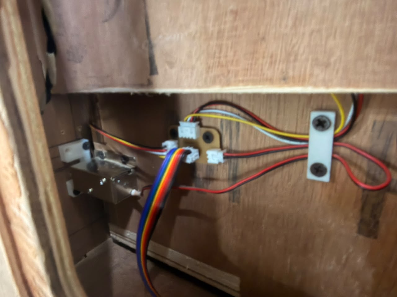
Solenoid Lock#
A solenoid lock is an electromechanical device that uses a solenoid to control the locking mechanism. When the solenoid is energized, it creates a magnetic field that moves a plunger or bolt, allowing the lock to open. When the solenoid is de-energized, a spring returns the plunger or bolt to its original position, locking the mechanism again. Solenoid locks are commonly used in access control systems, electronic door locks, and other applications where remote or automated locking is desired. They are available in various sizes and configurations, including fail-safe (unlocked when power is removed) and fail-secure (locked when power is removed) options.
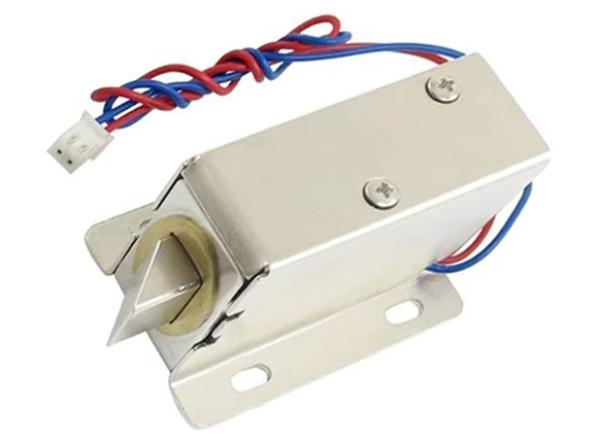
i will be 3 of such locks for my tool box for the 3 individual drawers
Main xiao Board#
This is the board with the microcontroller and it is connected to a sister board which has a MOSFET to control the high amperage switching of the solenoid lock.
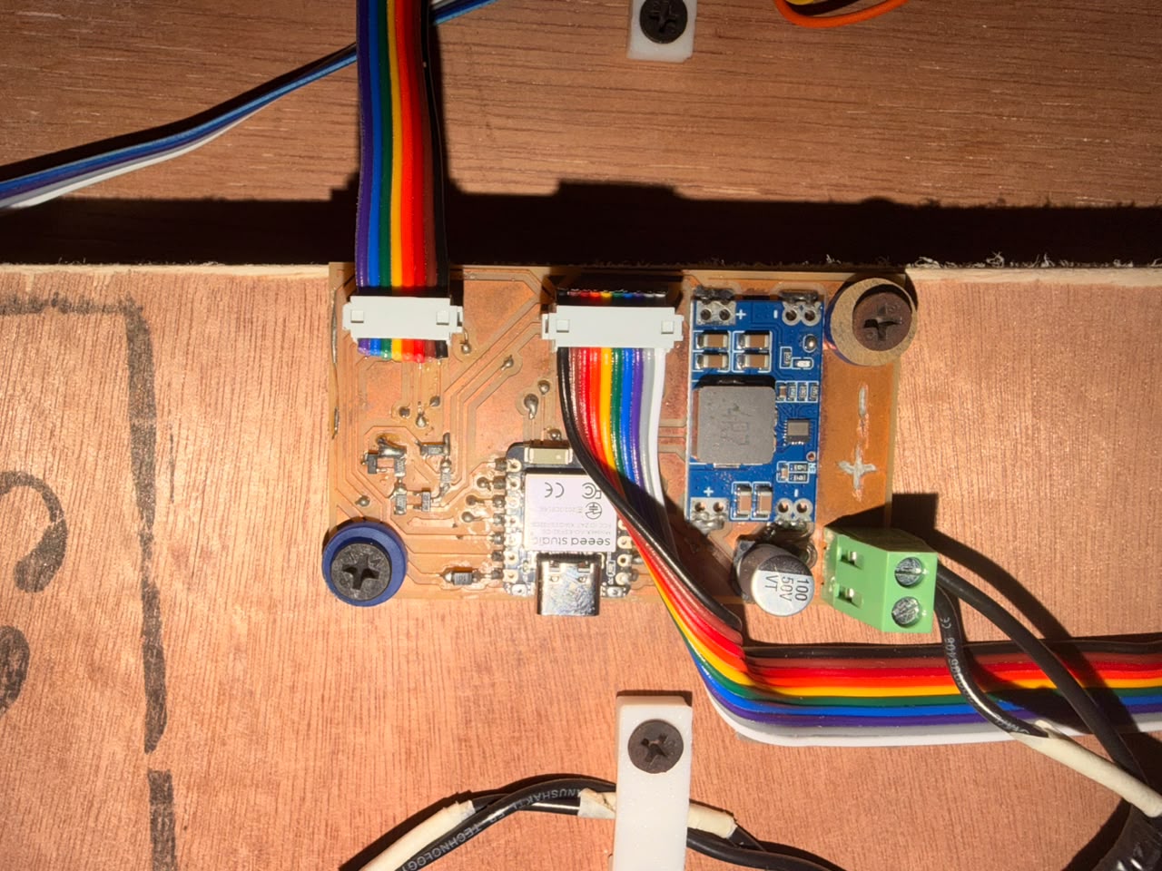
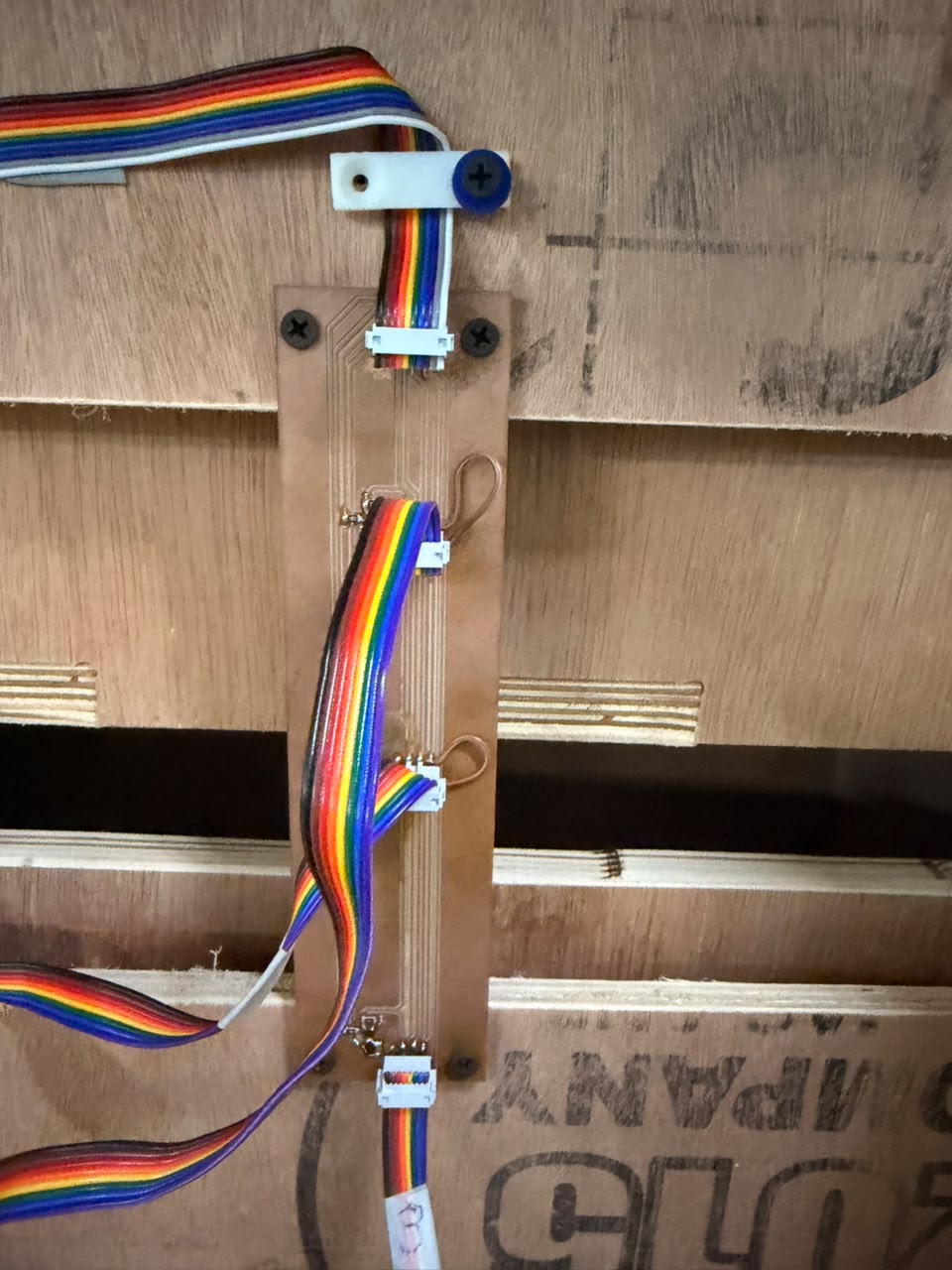
Sister Board#
This is the board which has the MOSFET and the solenoid lock connected to it.
How the Solenoid is Driven#
The solenoid lock is not wired straight to the microcontroller. It runs through a MOSFET on the sister board, which acts as the switch in between.
The MOSFET I used: NDS355AN — a small N-channel MOSFET (SOT-23, 30 V, ~1.7 A). The key word is logic-level: it turns fully ON from the low 3.3 V a microcontroller pin gives out. A normal MOSFET would need about 10 V on its gate, so it would barely switch on from 3.3 V and just get hot. Part link
Why a GPIO pin can’t drive the solenoid: a pin is made for sending signals, not power. It only pushes out 10–20 mA at 3.3 V, but the solenoid runs on 12 V and pulls far more current to move its plunger. Wire it straight to a pin and either the lock never moves, or the pin tries to pull too much current and burns out, which can damage the whole microcontroller.
Why the MOSFET is required: it acts as an electronic switch the microcontroller controls. The tiny signal from the GPIO pin goes to the MOSFET’s gate, and the MOSFET itself carries the big current, pulling it straight from the 12 V supply instead of from the pin. It is like a wall light switch: your finger uses almost no effort, but it controls a much bigger flow of electricity.
Why a flyback diode is needed: a solenoid is a coil of wire, which makes it an inductor, and inductors hate sudden current changes. When the MOSFET switches OFF, the coil throws back a high-voltage spike (back-EMF) that can be far above 12 V — enough to kill the MOSFET. My sister board has a flyback diode across the solenoid, fitted backwards to normal current. It does nothing during normal use, but when the spike appears it gives that energy a safe loop to circle the coil and fade away, protecting the MOSFET every time the lock turns off.
Solenoid Lock#
Output Demonstration#
A short clip of the full flow working on real hardware:
RFID scan → Solenoid unlocking → Toolbox opening
A valid RFID tag is scanned, the microcontroller drives the GPIO pin HIGH, the NDS355AN MOSFET switches 12 V to the solenoid, the plunger pulls back, and the drawer pops open.
For more details on the solenoid locks and the toolbox project, check out my Project Development page.
Reflections#
- The minimum circuit section of the ESP32-WROOM-32E datasheet is easy to miss but really important. Skipping the EN and IO0 pull-up resistors is the kind of mistake that comes back to bite you, since the module just won’t boot reliably without them.
- The 100 µF (470 µF in my case) cap on VMOT isn’t just a nice-to-have. The motor really does act like a generator when it slows down, and the voltage spike happens too fast to catch with a scope in time to save the driver.
- Figuring out which wires belong to which coil on the NEMA 17 with a multimeter, before wiring anything up, takes two minutes and saves a lot of frustration later.
References#
- Microcontroller interfaces: stepper motors — RS DesignSpark
- DRV8825 Stepper Motor Driver Arduino Tutorial — Last Minute Engineers
- DRV8825 Datasheet — Texas Instruments
- INA225 Datasheet — Texas Instruments
The above code was written with the assistance of Claude by Anthropic.
The Above documentation was proofread and grammatical errors were corrected by Claude by Anthropic.
AI PROMPT USED: “Proofread the following text and correct any grammatical errors and spelling mistakes.”