Week 12 - Mechanical Design (Machine Week - Part 1)#
Week 12 focused on mechanical design, specifically designing mechanisms and mechanical systems as part of the machine building project.
The aim was to understand mechanism design, motion systems, and structural considerations for machine building.
Group Assignment#
Part 1: Machine Design #
- Actuate and automate your machine
- Document the group project and your individual contribution
Part 2: Mechanical Design #
- Design a machine that includes mechanism + actuation + automation + function + user interface
- Build the mechanical parts and operate it manually
- Document the group project and your individual contribution
Individual Assignment#
Part 1: Machine Design#
- Document your individual contribution to the actuation and automation of the machine
Part 2 Mechanical Design#
- Document your individual contribution to the mechanism, mechanical parts, function and user interface of the machine
Software Used#
- SolidWorks for mechanism design
- Bambustudio for 3d printed arts slicing and printing
- Browser + Git for documentation
Group Assignments#
Click the button below to view our group project page, which includes details on our machine design, actuation, automation, and individual contributions.
Project Planning#
This was the first time any of us had to build something this big something that actually needed a whole team to pull off. Not just one person tinkering alone, but actual coordination between multiple people. That was new for all of us.
So we sat down over some coffee and just started throwing ideas around. One of the first ones was an automatic Connect 4 machine like, you play against the machine and it physically drops the pieces in. Pretty cool idea honestly.
But then somehow that got us thinking about pixel art. Connect 4 is just a grid of colored dots, right? So we thought what if we made a machine that creates pixel art by itself? That idea just stuck.
From there we had to set some rules for ourselves so things didn’t get out of hand. First was color we decided to keep it monochromatic (just one color) to keep things simple and not make the build more complicated than it needed to be. Second was size big enough to actually see the output clearly, but small enough to actually finish within the time we had.
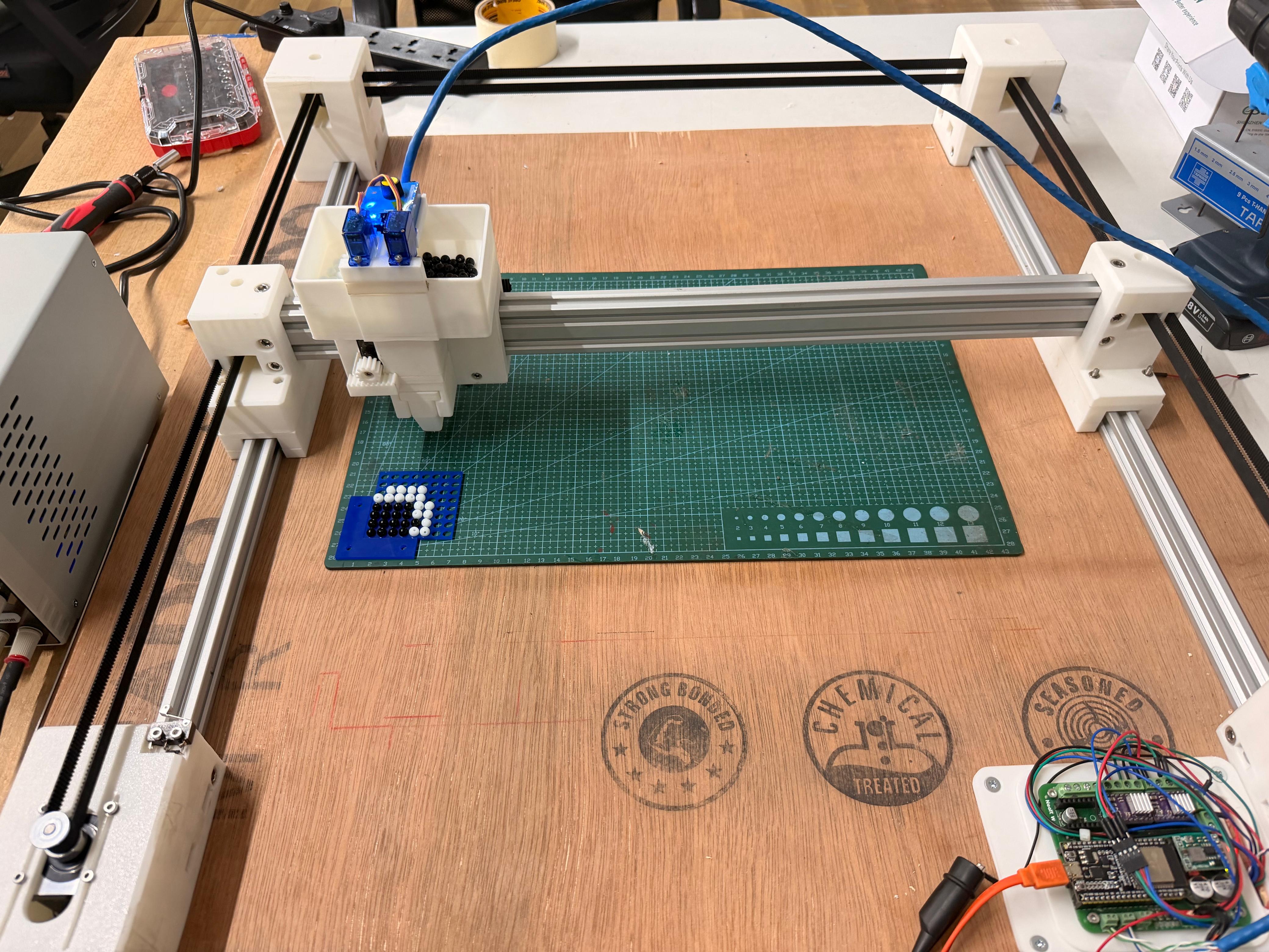
We landed on a 400mm × 400mm working area. Then came the question of what the “pixels” would actually be. We went with small jewellery beads they’re uniform, easy to handle, and look clean. The machine would place them one by one using an end effector on a CoreXY motion system.
After that we split up the work so everyone had something to own. I got assigned the CoreXY mechanism design so that’s what this documentation is about. Let’s get into it.
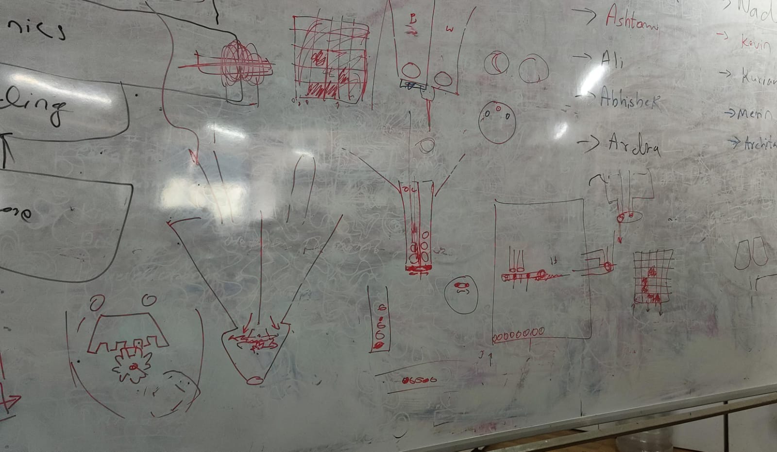 Sketching out ideas for the machine and how it would work. The final design ended up being quite different from this, but this was a good starting point.
Core XY#
I had seen CoreXY machines before, like 3D printers and laser cutters, but only from the outside. I had never taken one apart or built one, so I had no idea how it actually worked on the inside. So I went down a bit of a rabbit hole trying to figure it out.
I started by just Googling “what is CoreXY” and one of the first things that came up was corexy.com , which had a pretty solid breakdown of the whole system.
After that I had a conversation with Claude by Anthropic to get a clearer picture, which I’ve included below, both as reference and to give credit to the AI that helped me understand it.
By the end of all that, I had a good enough understanding to actually start designing the mechanism for our machine.
AI-generated content below (Claude by Anthropic).#
PROMPT : Write a detailed explanation of the CoreXY motion system, including how it works, its advantages, and design considerations.
⚙️ The CoreXY Motion System#
CoreXY is a parallel motion system used to drive a tool head across the X and Y plane using two stationary motors and a pair of synchronised belts. It was developed by Ilan Moyer at MIT in 2012 and has since become a popular choice for 3D printers, plotters, and lightweight CNC machines including this project’s bead-placement head.
Unlike a conventional Cartesian setup, where one motor rides along the gantry and adds mass to the moving assembly, both CoreXY motors are bolted to the frame and never move. This keeps the moving mass low, which is the core reason the system can run at high speeds and high accelerations without losing accuracy.
🔄 How It Works#
The two motors are linked to the tool head through a pair of belts routed in a characteristic crossed “H” pattern. Neither motor controls a single axis on its own; instead, both motors share the load for every move, and the resulting motion is the combination of how the two motors turn.
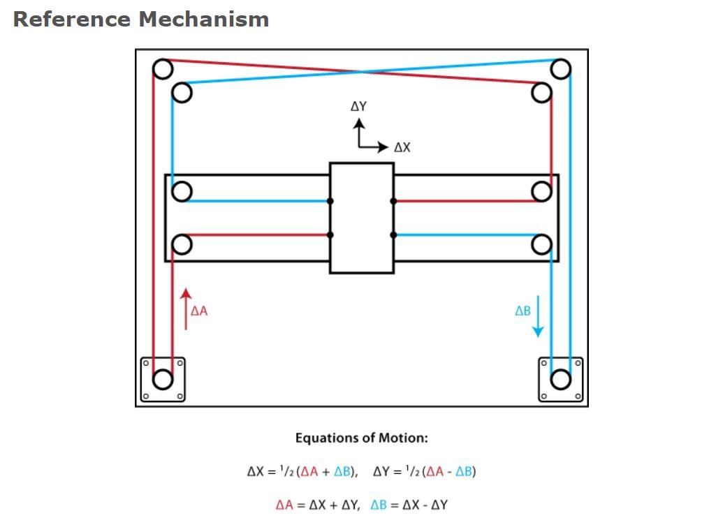
Motor A Motor B Resulting Motion Turns same direction Turns same direction Head moves along one axis Turns opposite direction Turns opposite direction Head moves along the other axis Mixed speeds / directions Mixed speeds / directions Diagonal motion The kinematics reduce to two simple equations, where A and B are the rotations of each motor:
ΔX = ½ (ΔA + ΔB)
ΔY = ½ (ΔA − ΔB)
This coupling is handled automatically in firmware (GRBL / FluidNC), so from the host side the machine still accepts standard Cartesian G-code.
✅ Advantages#
- Low moving mass motors stay fixed to the frame, so only the head and belts move. This allows high speed and acceleration with reduced ringing/ghosting.
- Z-axis stays independent the XY system is self-contained, making the design well suited to taller builds.
- Symmetric load sharing both motors contribute to every move, distributing torque evenly.
⚠️ Design Considerations#
- Belt routing is critical. The two belts must run on different planes so they don’t collide, while staying parallel to the axes. Sloppy routing causes binding or crashes.
- Belt tension must be balanced. Uneven or loose tension introduces skew, backlash, and positional error.
- The frame must be square. Any deviation from a true rectangle skews the coordinate system, producing parallelogram-shaped output instead of square geometry.
Design#
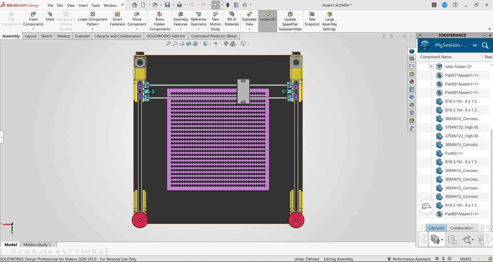
So i started out the design process by creating a rough cad model so that i canconvey my idea to my teammates. I used SolidWorks to create a simple model of the CoreXY mechanism, including the frame, belts, pulleys, and a placeholder for the end effector for bead placement.
I had used solidworks for the design of the machine as i am very familiar with the software.
Please note this was just a design to share the idea so i hadnt bothered to make it very detailed or accurate, the final design ended up being quite different as we had to make adjustments based on the parts we had and the feedback from our teammates.
In this design the pulleys the plane etc are just placeholders and not the actual parts we used, the final design had more accurate representations of the parts we had.
First design#
After this deign was made , i had spoken to my team and the intructors Mr Jogin Francis and Mr Sreyas George who gave a lot of expeirnce in building machines and they gave me a lot of feedback on the design and how to improve it. They also helped me understand the limitations of the parts we had and how to work around them.
they had made be realise that the current deign i had in mind for the gantry system ( i had drawn isnpiration from the x axis gantry sustem used by creality ender 3 s1 pro which was a 3d printed i had a lot of experience playing around with) would be too much of an overcomplication and had suggesed a gantry design that was created by jake read https://github.com/jakeread https://uwaterloo.ca/architecture/jake-read which was a much simpler design and would be easier to build.
My Gantry Design#
Jake’s Gantry Design#
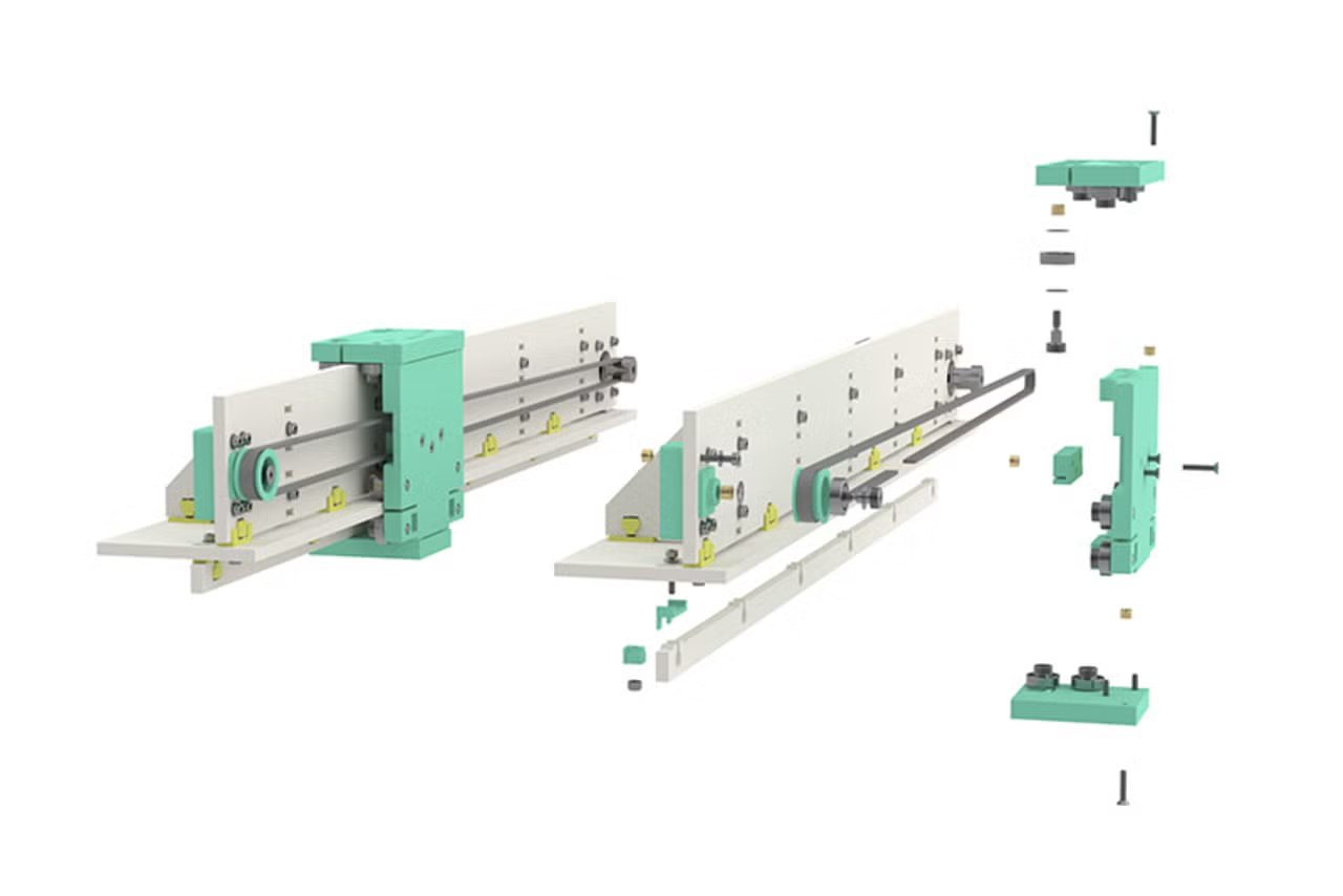
After that i had redesigned the gantry system based on jakes design with the help of my instructor Sreyas and then we had a final design that we were happy with and that we could actually build with the parts we had.
Initial design by sreyas based on jakes design
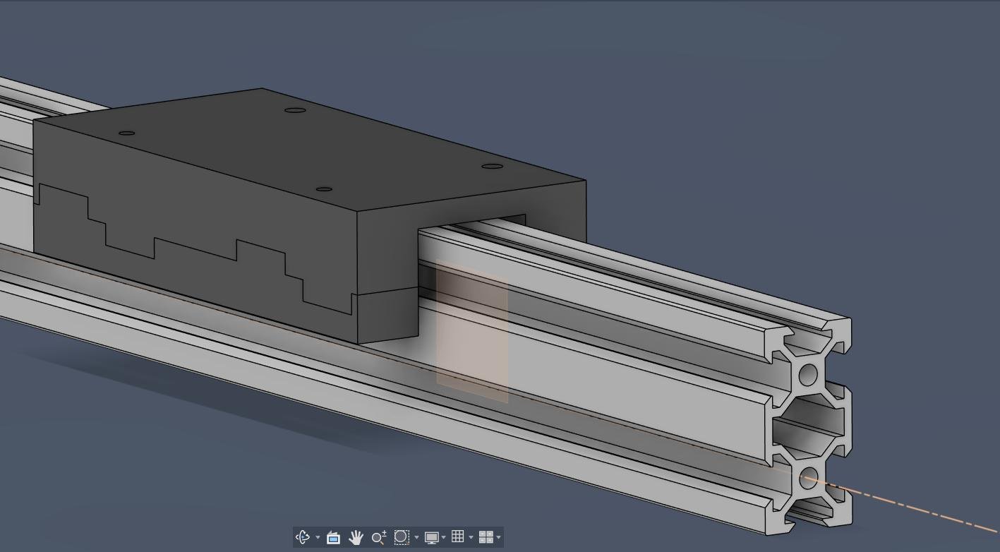
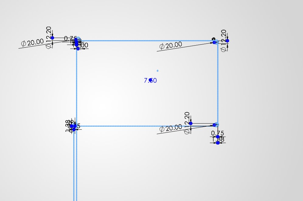
Design Adjusted by me inorder to fit the 20x40 aluminum extrusions we had planned on using.
After the gantry got sorted i moved ahead with the design of the entire machine for which first i drew a sketch with the belt loops
Left belt loop
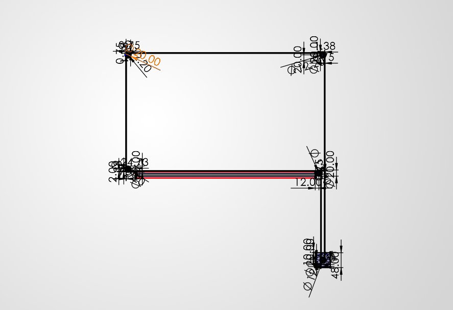
Right belt loop
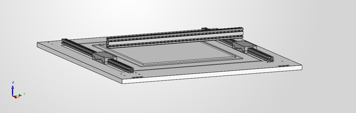
Then i had placed the bottom Base and the aluminum extrusions at the required positions with the gantry which was designed earlier
The height for the x akis gantry placement was decided after discussion with my teammate Kevin Jijo who was in charge of the end effector design and he had told me the height at which the end effector would be able to place the beads properly without any issues.
then i moved onto the design of the 4 corner bloacks which would hold the aluminum extrusions in place and the pulley and motors would be mounted on top of these blocks. I had designed these blocks in such a way that they would be easy to print and would also be strong enough to hold the aluminum extrusions in place.
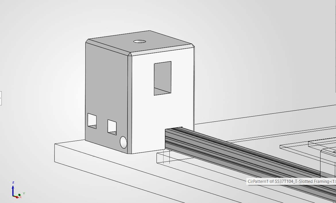
Corner block
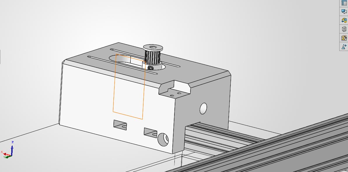
Motor Block
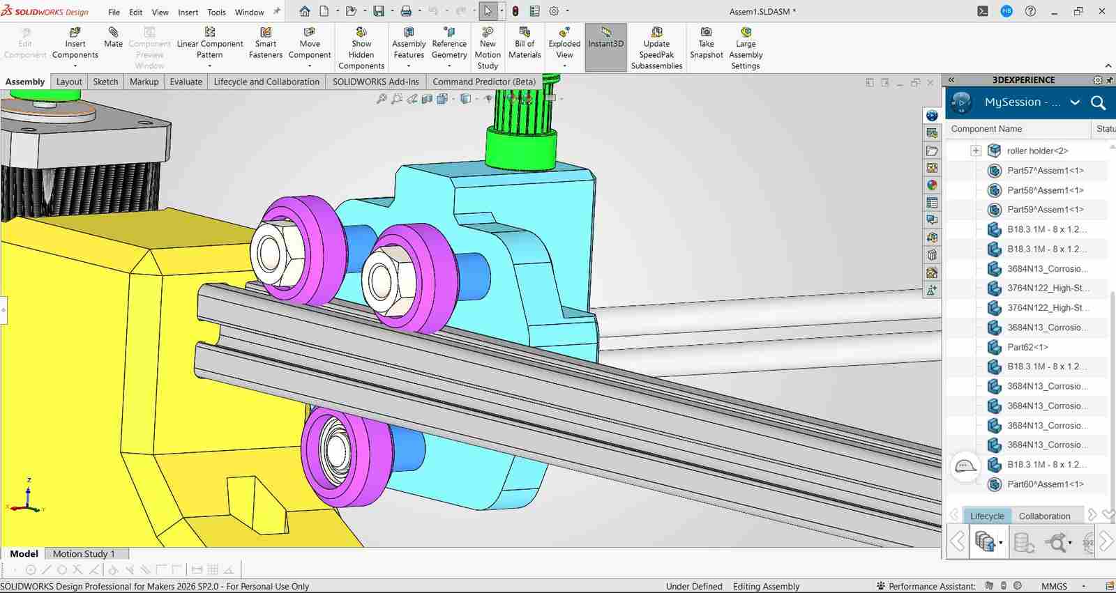
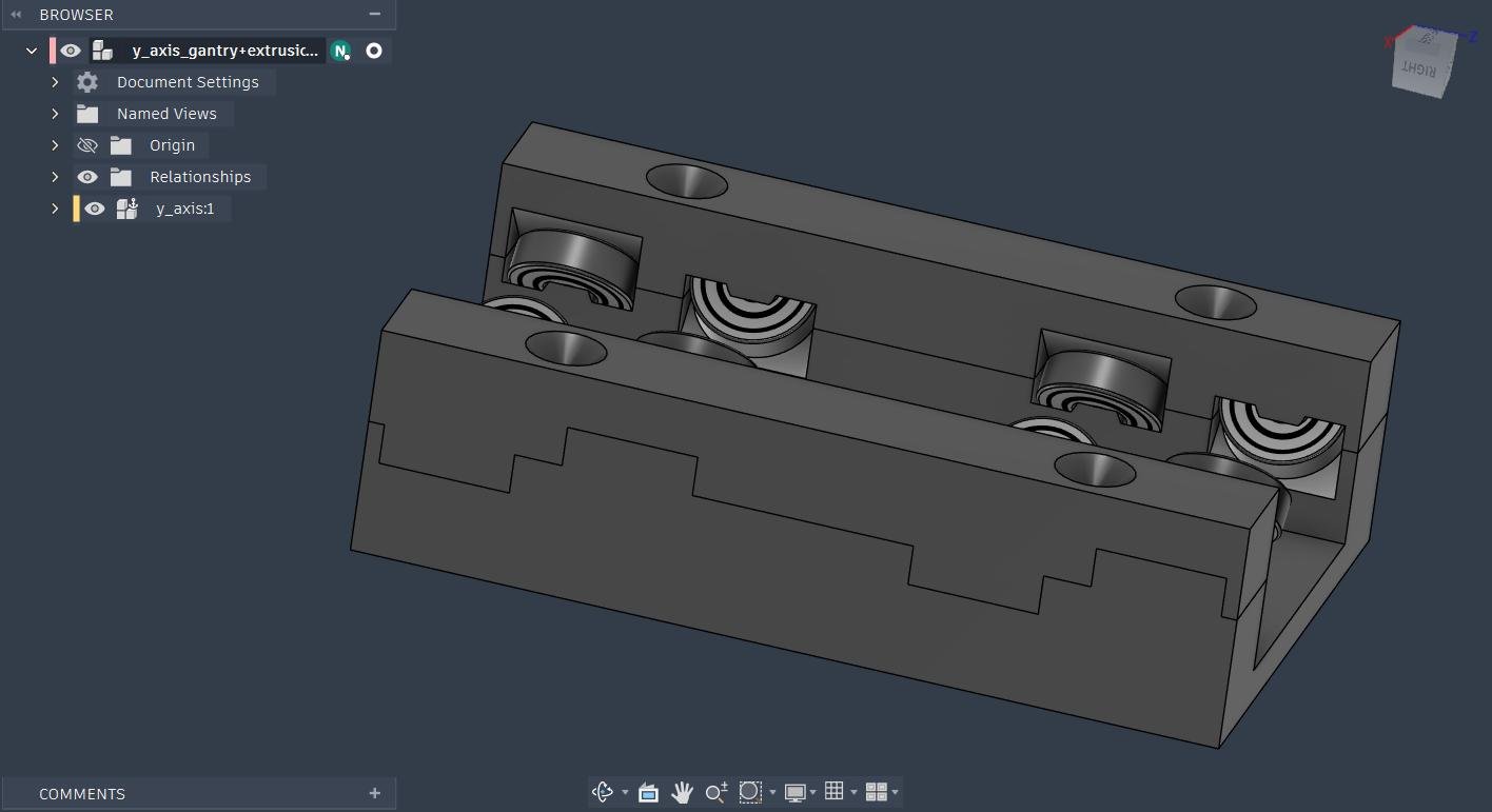
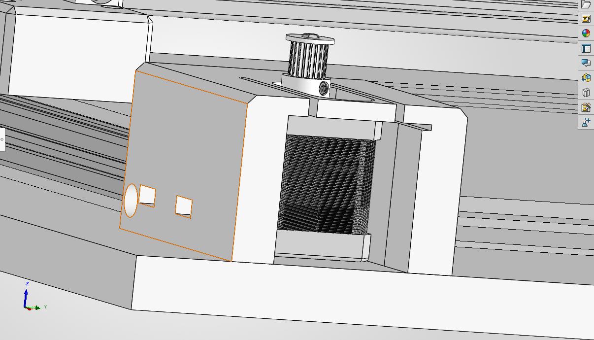
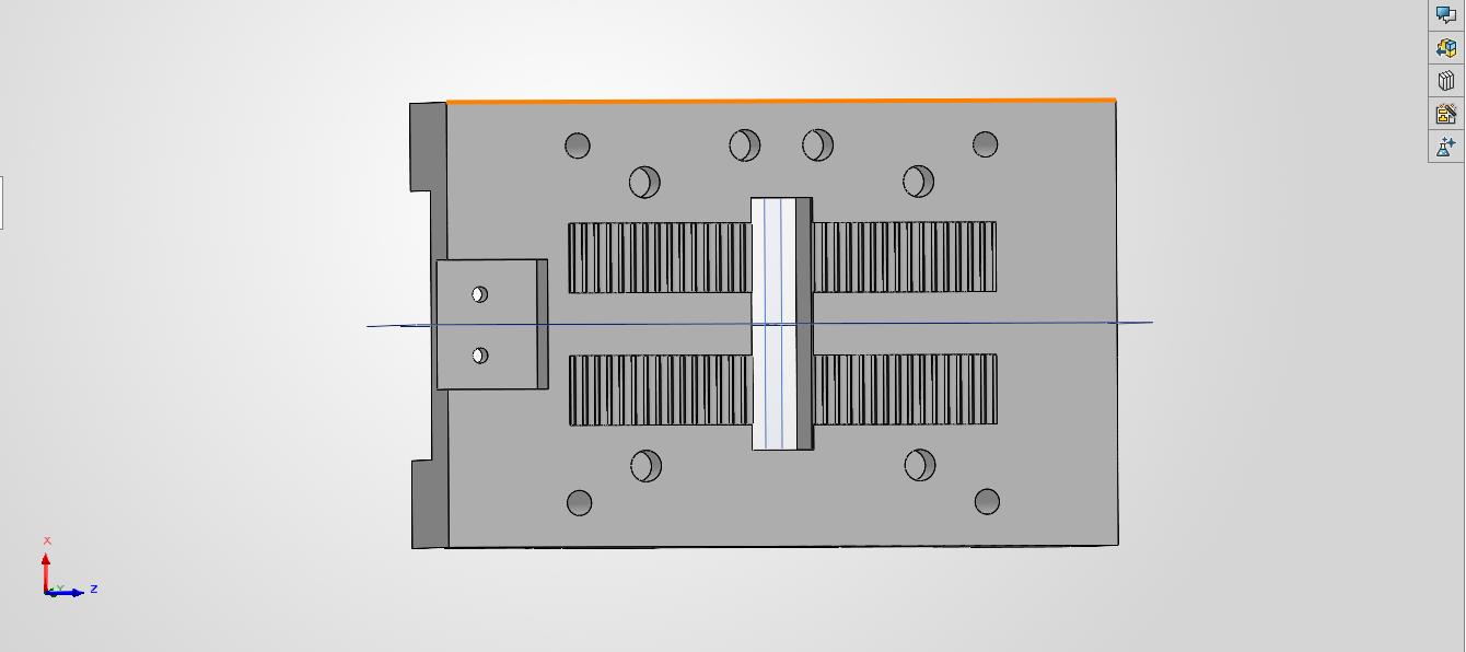
after this i had moved onto the design of the blocks that woud hold the pulleysand the x gantry aluminum extrusions in place .
Gantry block
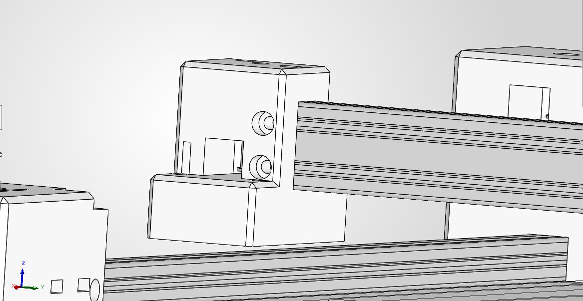
then i had modified the design of the x gantry so that it can be used to tighten the belt of the pulley by tightly pulling the belt and using the ba cap to screw them into place
belt tightening mechanism
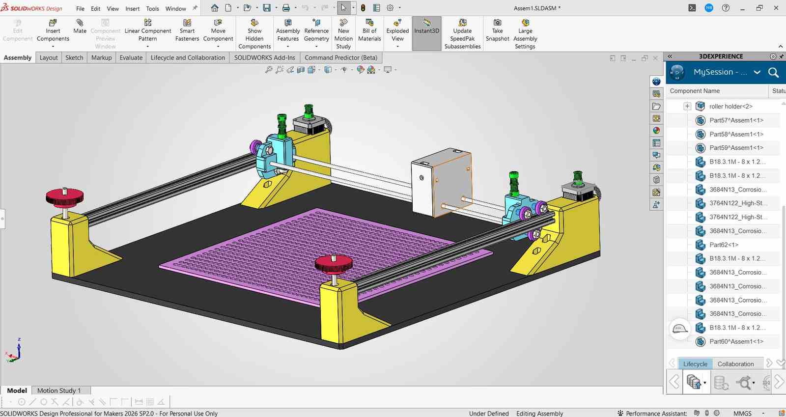
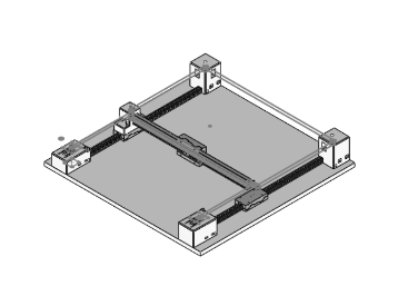
Final CAD Assembly of the CoreXY mechanism with all the parts in place and the belt loops in place.
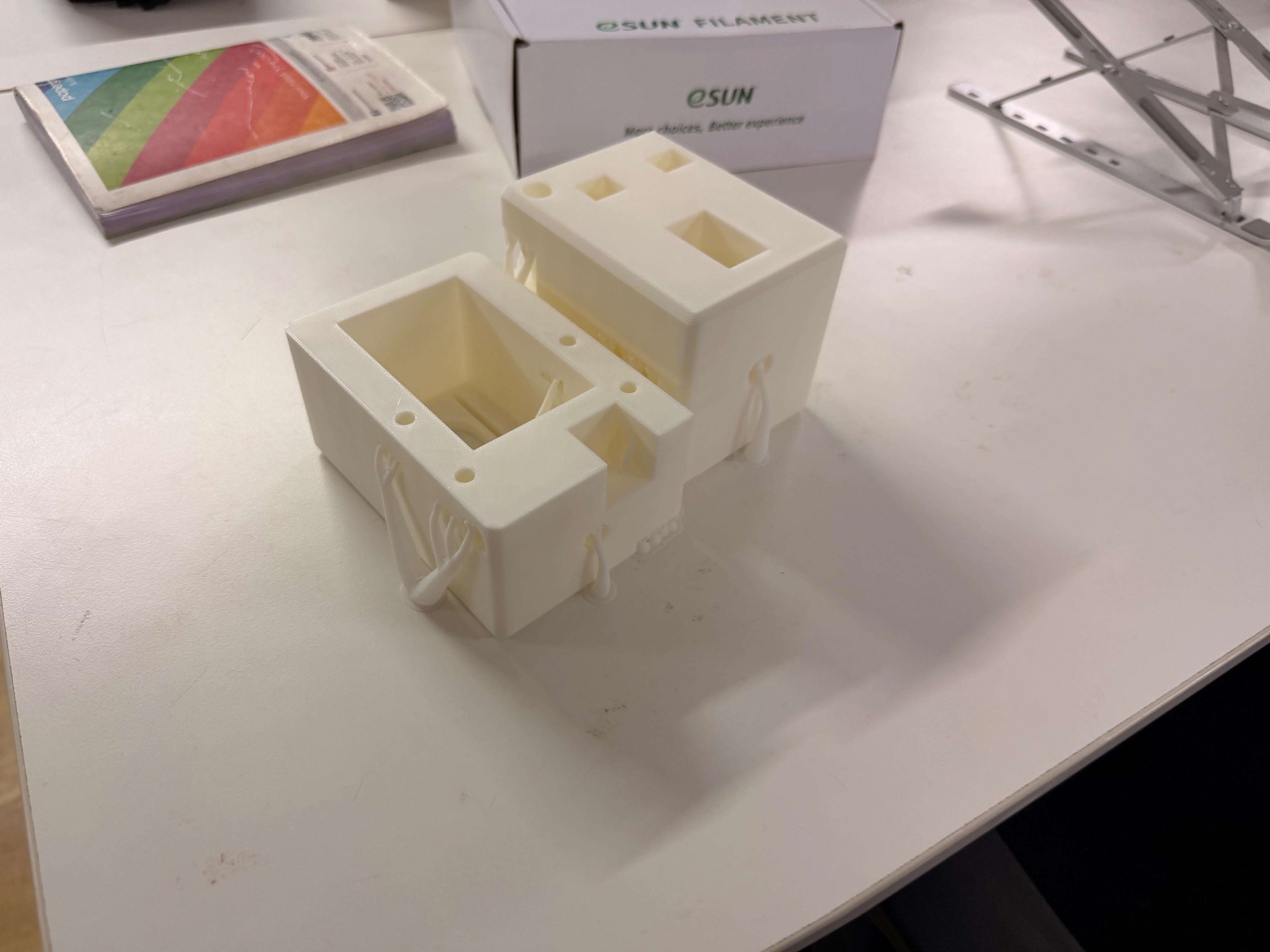
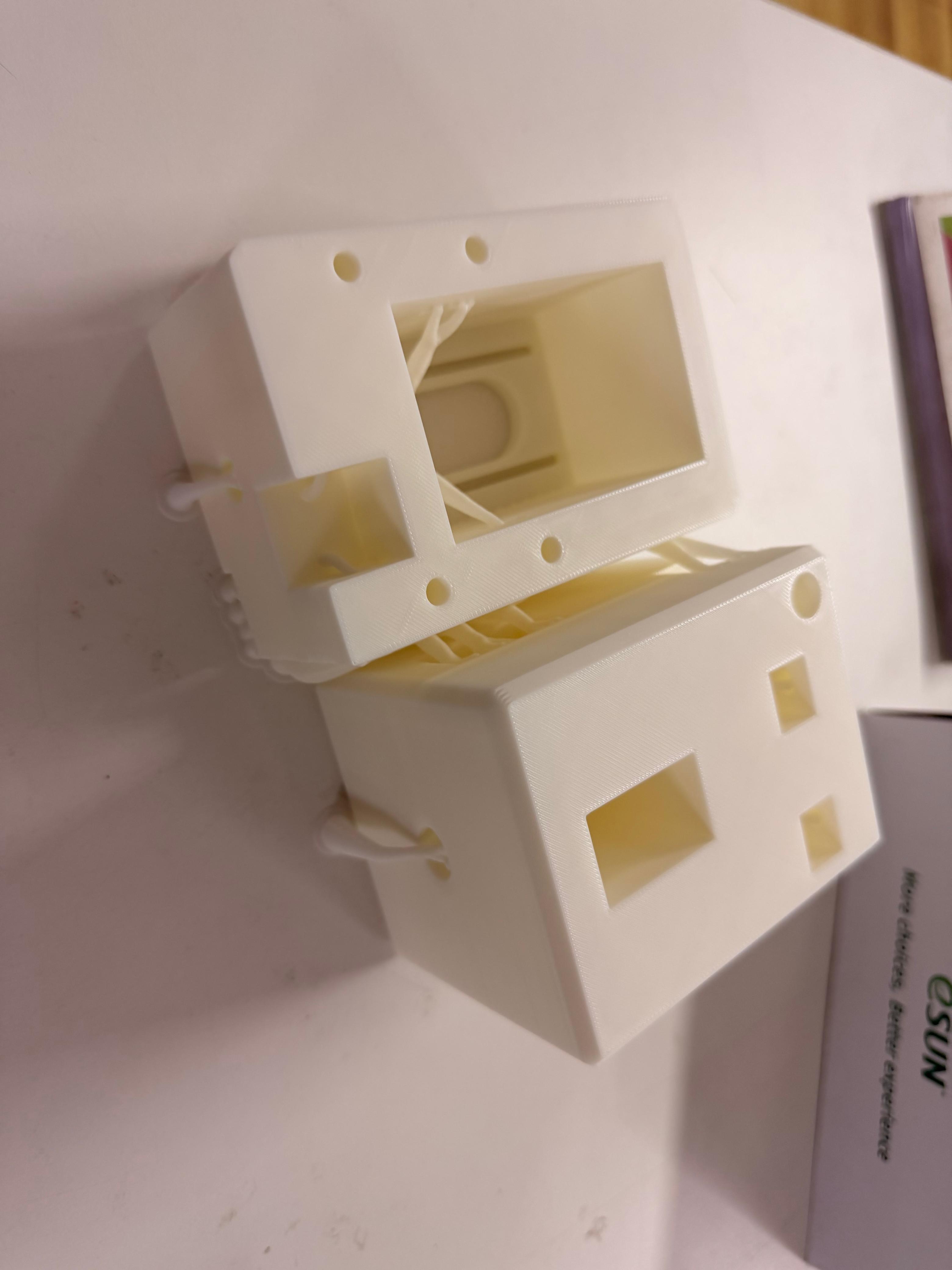
3D Printing#
Gantry System#
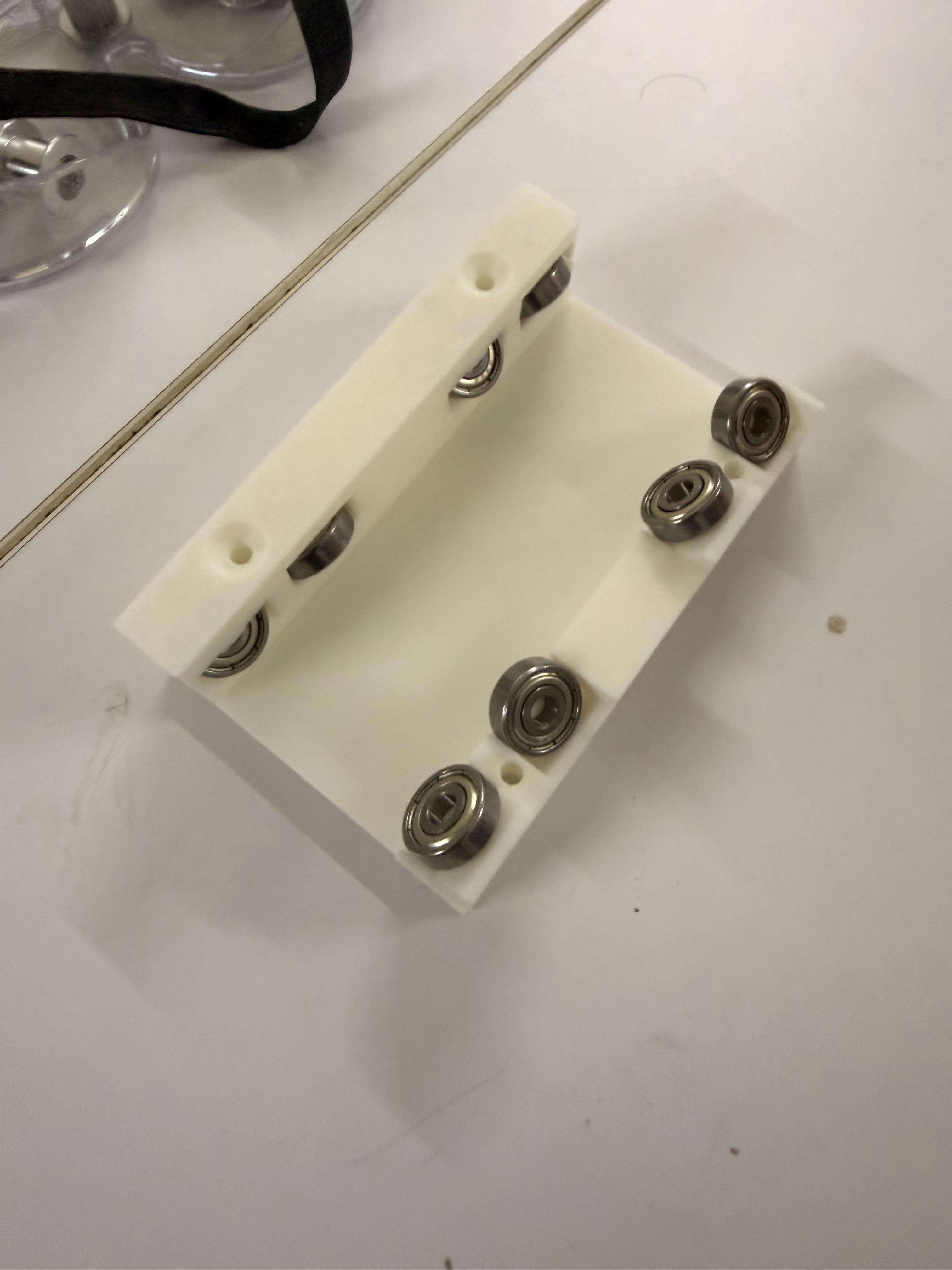
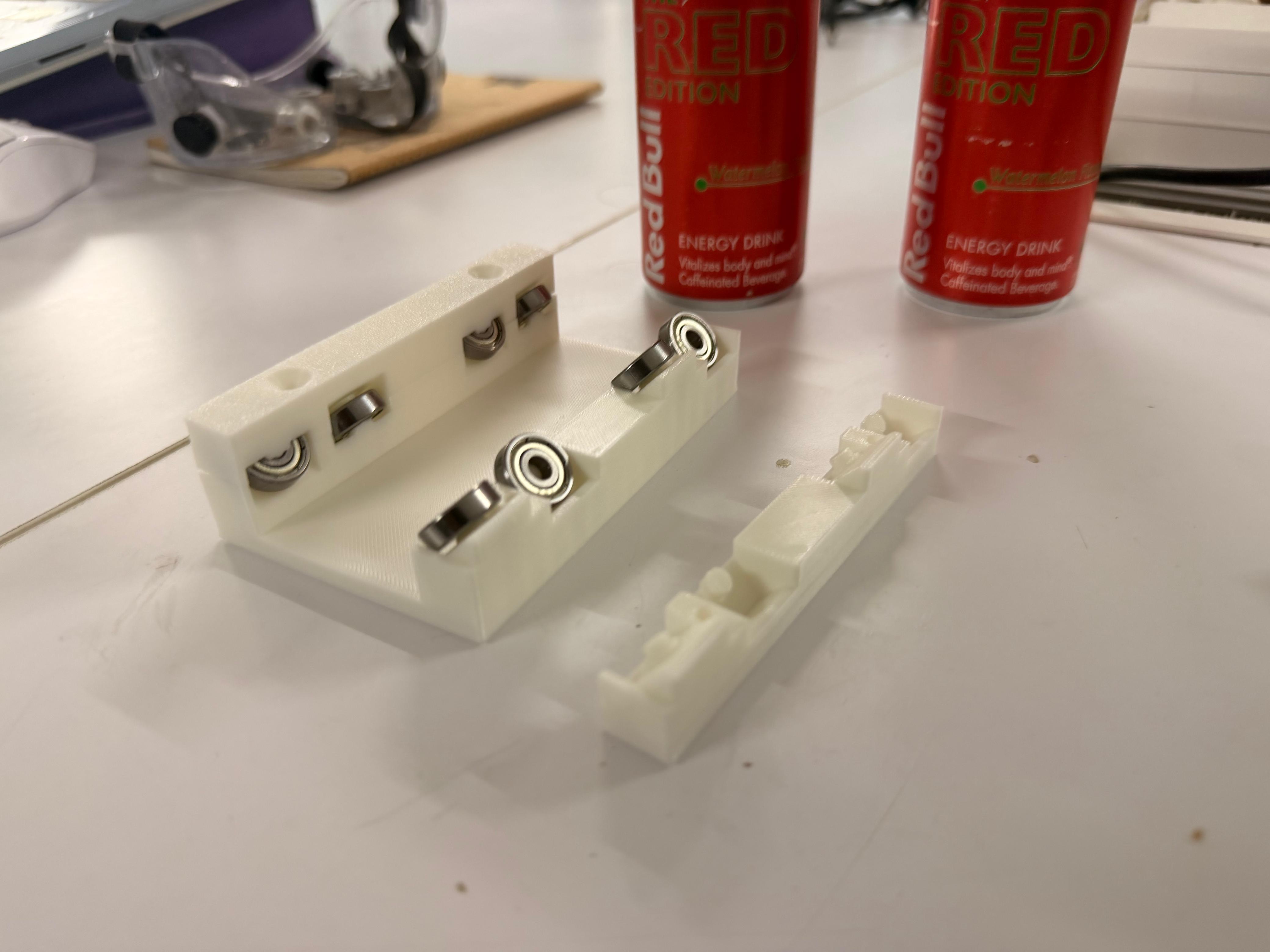
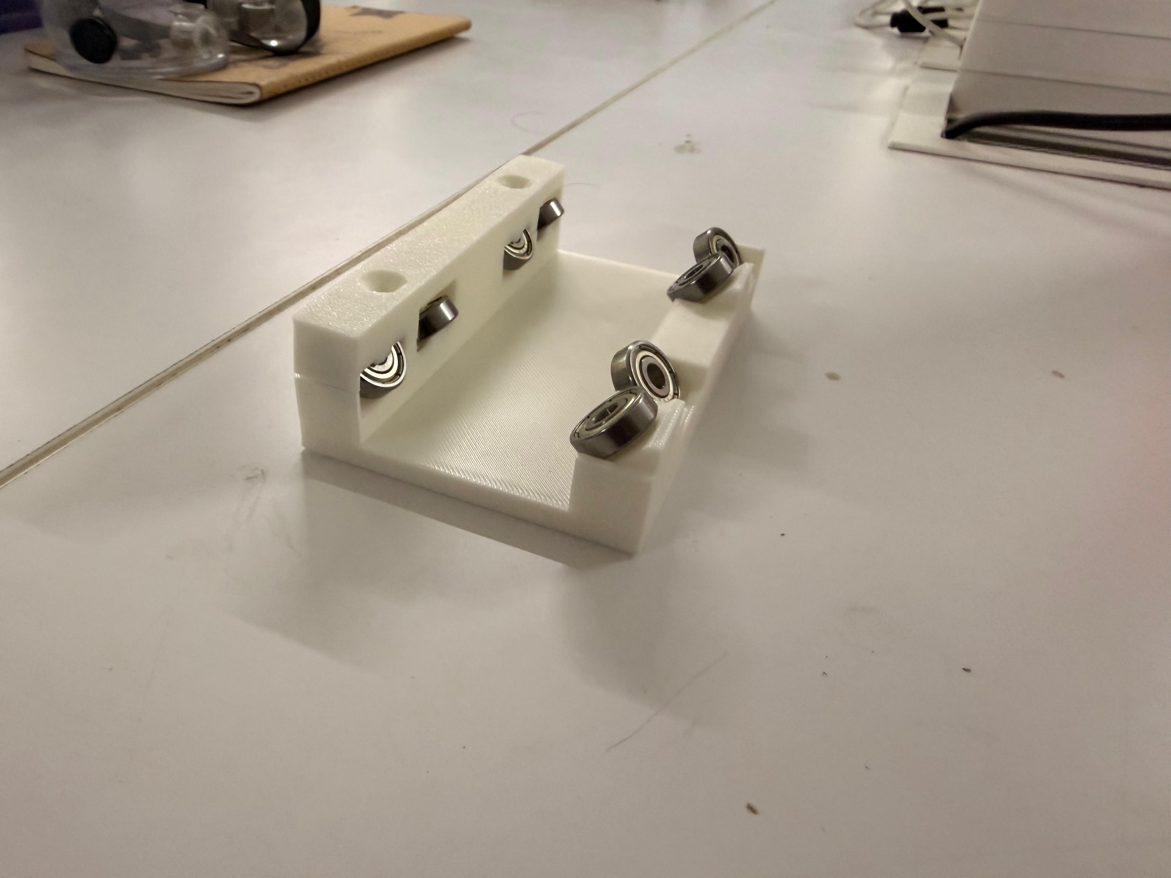
Corner Blocks#
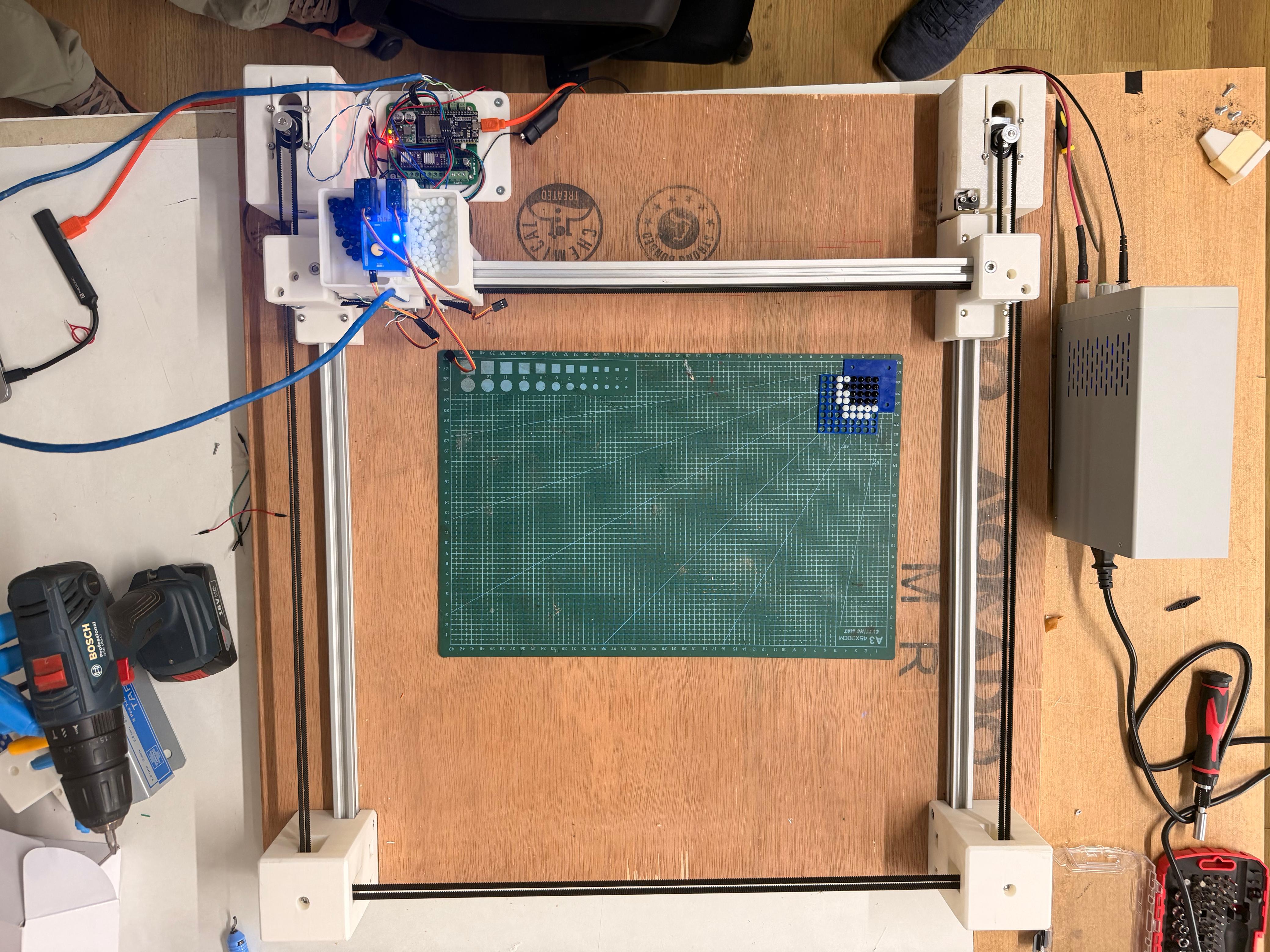
Assembly#
Finally Assembled Machine#
Sorting Beads of a Specific Size#
Machine Movement Test#
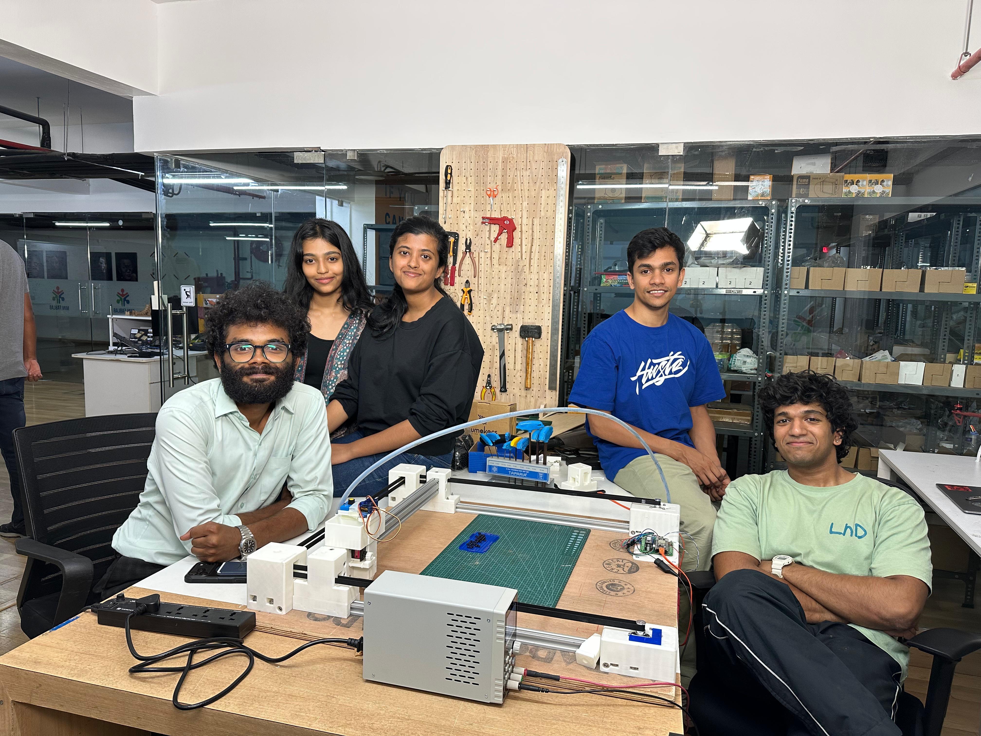
Our Team#