Week 03 – Computer Controlled Cutting#
So its my third week of Fab Academy, and yeah its special because its week 3 😄
also im lowkey a fan of multiples of 3 so lets go with that.
Week 3 focused on computer-controlled cutting, specifically using the laser cutter and vinyl cutter.
The aim was to understand how digital designs translate into precise physical parts, and how machine parameters like kerf, speed, and power directly affect accuracy and fit.
This week built naturally on Week 1 (principles, tools, documentation) and Week 2 (CAD and parametric design), where design intent and parametric thinking were already established. Here, those designs were finally tested against real machines and materials.

Group Assignment#
- Completed lab safety training
- Characterized the laser cutter by testing:
- Focus
- Power
- Speed
- Rate
- Kerf
- Joint clearance
- Different joint types
Individual Assignment#
- Cut a design using the vinyl cutter
- Designed and laser-cut a parametric construction kit
- Accounted for laser kerf in the design
- Documented the design, cutting process, and assembly
Extra Credit Goals#
- Designed parts that can be assembled in multiple ways
- Included non-flat / interlocking elements
- Used engraving along with cutting
What I Learned#
- Laser cutting accuracy depends heavily on machine calibration and material testing
- Kerf varies with material, power, speed, and focus
- Parametric design makes it easier to adapt designs after kerf testing
- Press-fit joints require balancing tight fit and material safety
- Vinyl cutting requires a different mindset compared to laser cutting
- Proper documentation helps reproduce results and avoid repeated mistakes
Software Used#
- Laser Cutter Control Software - Trotec Job Control for sending jobs to the laser cutter
- Browser + Git for documentation (same workflow as Week 1 & 2)
- Mods Project for sending vinyl cutting jobs
- Inkscape for preparing cutting files
- Fusion 360 for parametric modeling
- Deepnest for nesting the construction kit parts https://deepnest.io/
- Bambu Studio for creating the 3d model of a human from image https://www.bambulab.com/bambu-studio
- kiri:moto for slcing 3d model into the svg files for laser cutting https://grid.space/kiri/
Weekly Schedule#
| Day | What I Did |
|---|---|
| WED | and introduction to computer-controlled cutting |
| THU | Lab safety training |
| FRI | Laser cutter characterization and kerf testing Joint clearance testing and press-fit experiments |
| SAT | Parametric construction kit design |
| SUN | Parametric construction kit design (Continued) |
| MON | Vinyl cutting , Laser cutting and engraving , assembly testing |
| TUE | Documentation and regional review |
Lab Safety Training#
I’m adding the group assignment page here for reference:
🔗 https://fabacademy.org/2026/labs/kochi/group_assignmetns/week03/
My Reflection on Lab Safety#
One thing that really hit me this week is that the machines in the lab are not kids toys.
They are powerful tools that can hurt you in very serious ways if you’re careless.
So you need to treat the machines with mutual respect and be extremely alert while working with them.
Lab Safety Training (Individual Understanding)#
General Lab Safety#
Safety is the top priority in the lab. Before operating any machine or handling materials, it is important to understand the risks involved. The lab contains high-powered machines, sharp tools, chemicals, and pressurized systems.
From the training, these were the main safety practices I learned and followed:
- Always wear proper PPE such as safety glasses, gloves, and closed-toe shoes
- Avoid loose clothing, jewelry, and keep long hair tied back
- Maintain a clean and organized workspace to avoid accidents
- Check machines before use and report any issues immediately
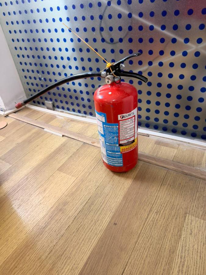
- Be aware of emergency stops, fire extinguishers, first-aid kits, and eyewash stations
The locations of the fire extinguisher, emergency exits, and the lab floor plan were also clearly explained.
CO₂ Laser Cutter Safety#
The CO₂ laser cutter is a powerful machine used for cutting and engraving. Because of the high-intensity laser beam, it poses risks such as fire hazards, eye injury, and exposure to toxic fumes.
Certain materials like PVC and ABS should never be laser cut, as they release hazardous gases.
Exhaust System#
The laser cutter is equipped with an exhaust filtration system that removes smoke and fumes generated during cutting. The system uses filters and activated charcoal to absorb harmful gases and VOCs released from materials like wood and acrylic.
Before cutting:
- The exhaust system must be ON
- The laser must be properly focused
- The material should be secured on the bed
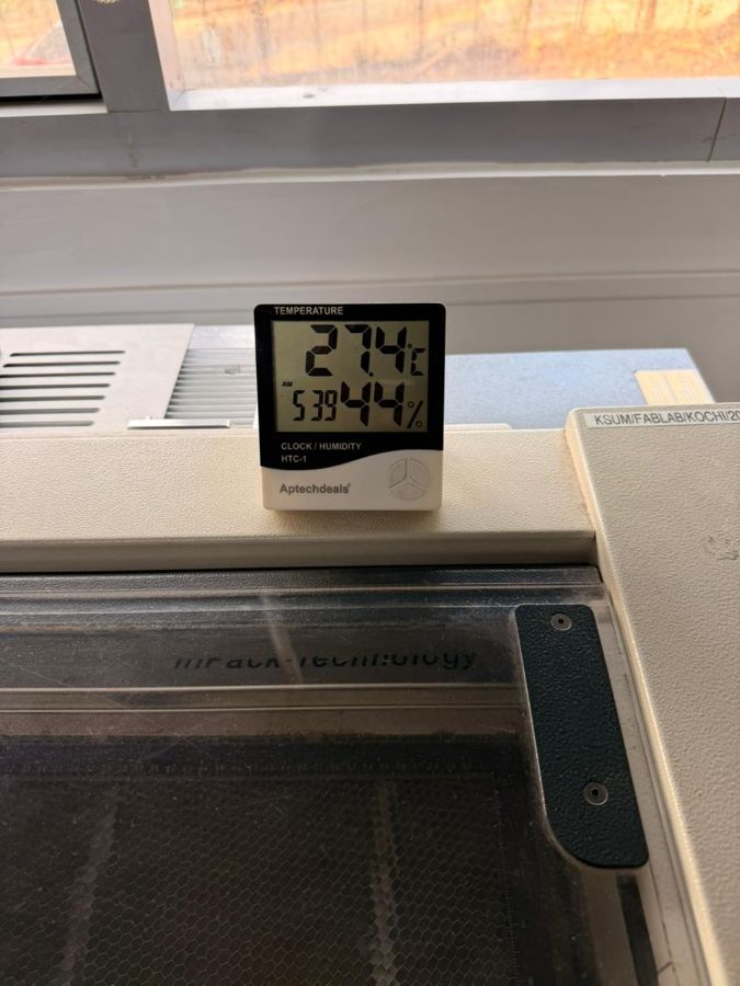
- Room temperature should be maintained for safe operation
During cutting, the machine must be continuously monitored to prevent fires. If a fire occurs, the machine should be paused immediately while keeping the lid closed. A CO₂ fire extinguisher should be used if required.
What to Do If a Fire Starts in the Laser Cutter#
- Do not open the lid immediately
- Pause the laser cutter if it is safe to do so
- Cover small flames with a larger non-flammable material
- Monitor the situation
- Use a CO₂ fire extinguisher if needed
- Call for help and evacuate if the fire cannot be controlled
Vinyl Cutter Safety#
The vinyl cutter also requires careful handling:
- Blade must be installed correctly and adjusted to proper depth
- Vinyl sheet must be aligned properly
- Hands should be kept away from moving parts
- Machine should be paused before clearing jams
- Excess vinyl should be removed carefully using a weeding tool
Vinyl Cutting#
Machine Used#
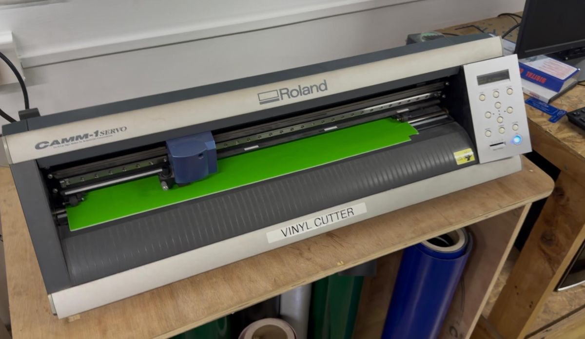
Roland CAMM-1 Servo – Vinyl Cutter
A vinyl cutter is a computer-controlled machine that uses a blade to make precise cuts on vinyl sheets. It is mainly used for stickers, decals, and signage.
 https://www.rolanddga.com/support/products/cutting/camm-1-gx-24-24-vinyl-cutter
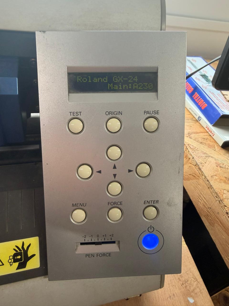
Machine Controls#
- Roll or sheet selection
- Maximum cutting force
- Cutting tool and blade depth
Setup Process#
- Load vinyl by releasing the loading lever
- Align vinyl with pinch rollers
- Lock the lever
- Inspect and adjust blade depth
- Set origin and perform a test cut
Vinyl Project – Tarusa Motorsports Sticker#
This week I designed and cut a sticker for Tarusa Motorsports, the off-road buggy building team I am part of. https://www.instagram.com/tarusamotorsport/
Workflow:
- Opened Inkscape
- Imported the team logo

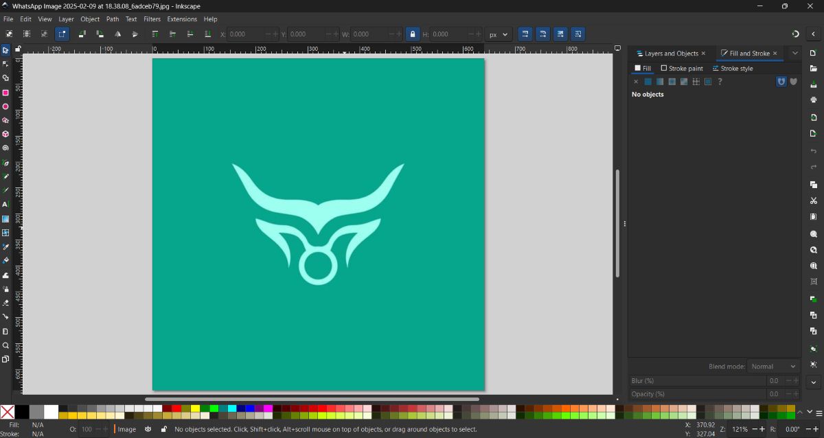
- Used Trace Bitmap to convert it into a vector
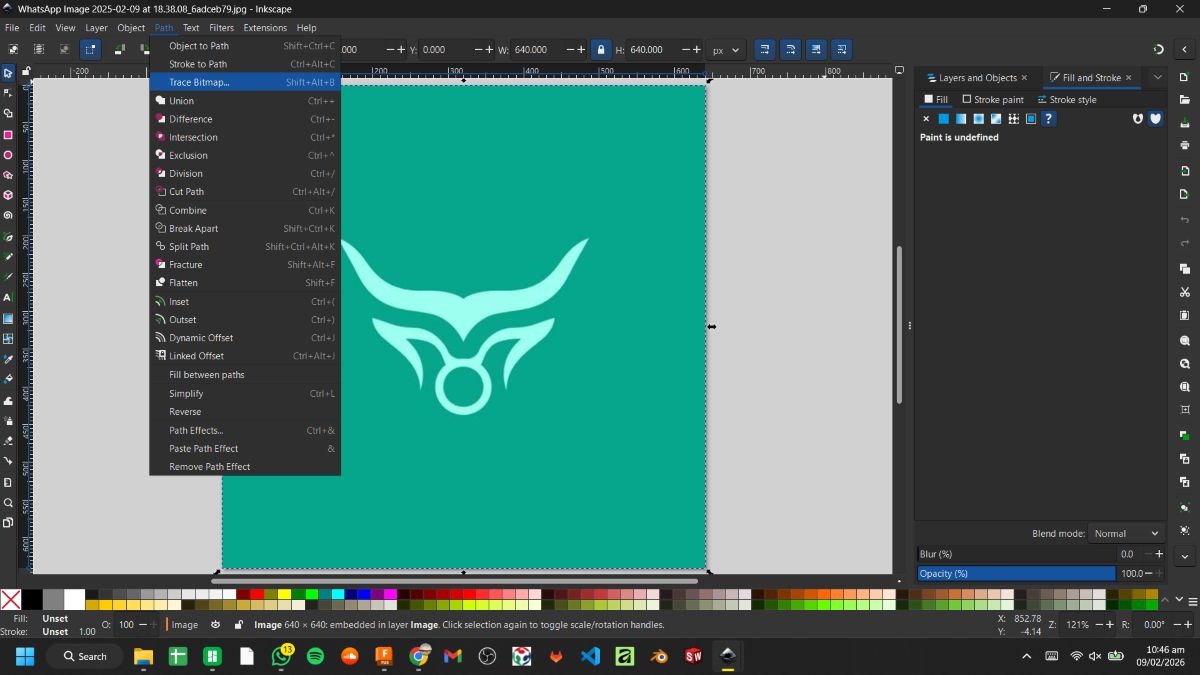
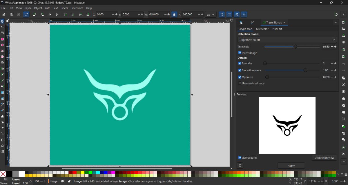
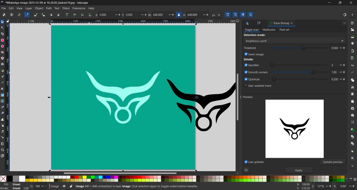
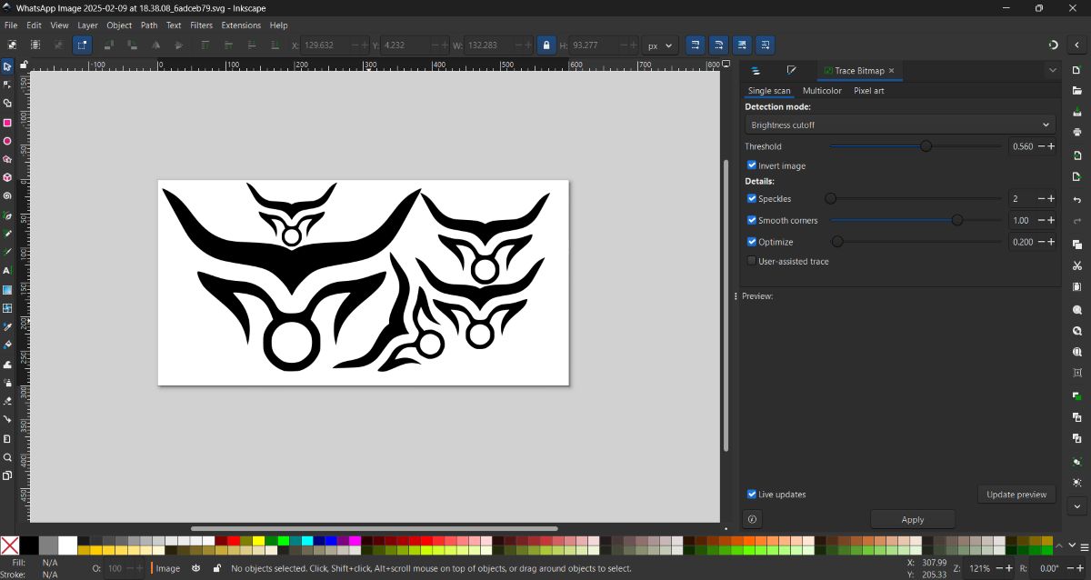
- Cleaned the vector and adjusted paths
- Arranged multiple sizes on the canvas
- Sent the file for cutting using the Mods Project workflow
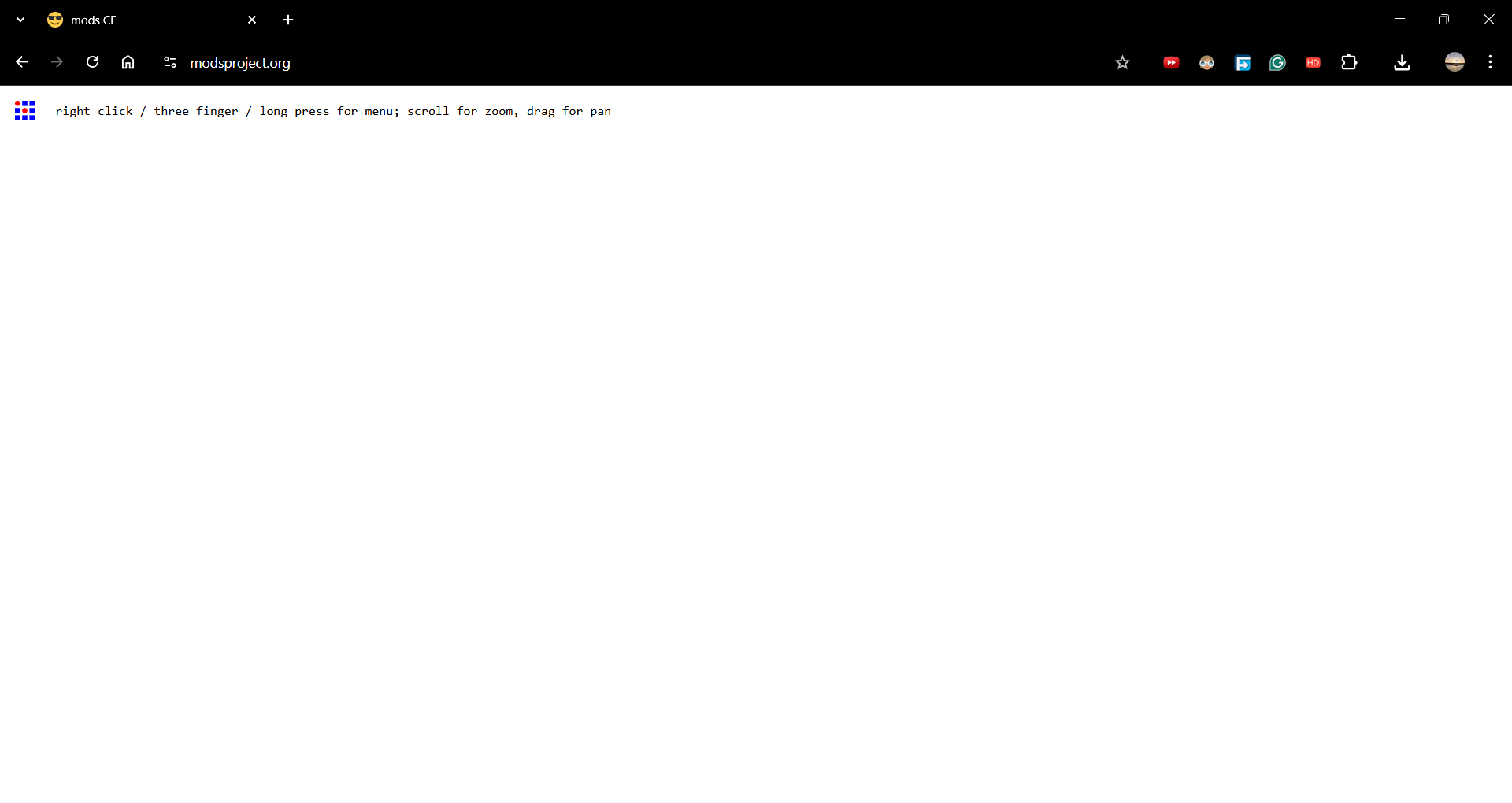
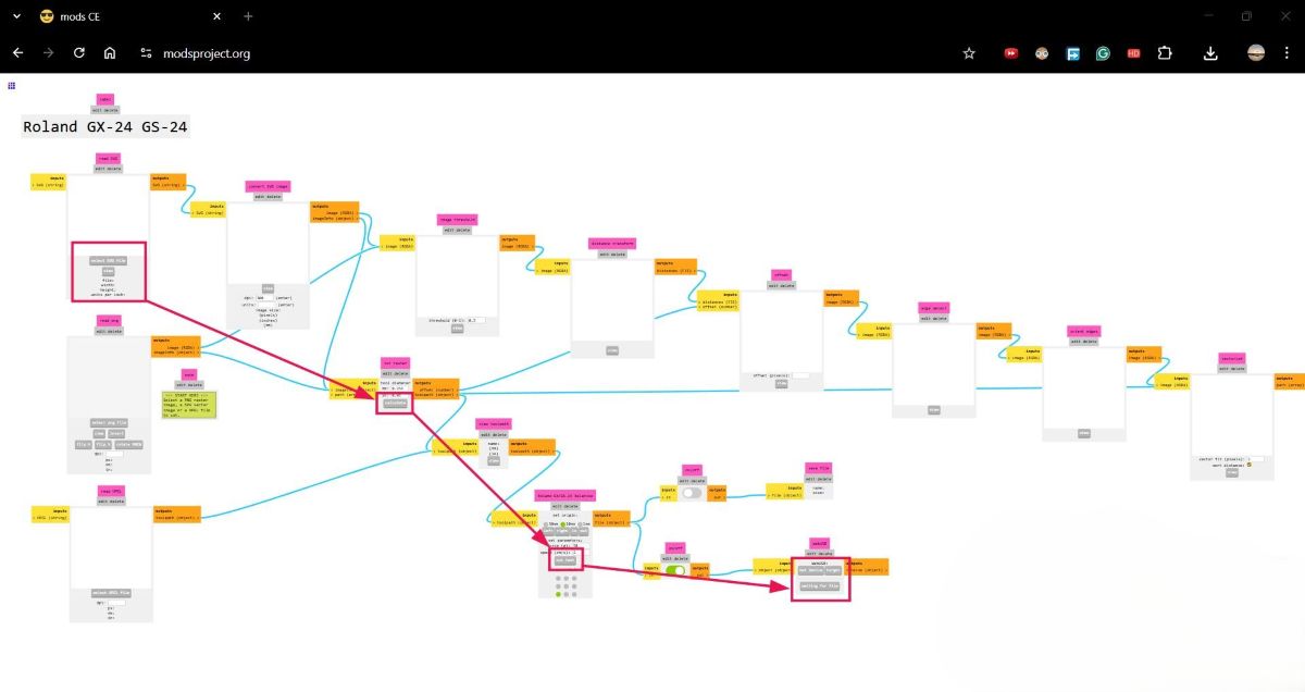
Vinyl Cutting Using Mods Project#
For sending the vinyl cutting job to the machine, I used the Mods Project web application.
I first opened the Mods Project website:
Selecting the Program#
After opening the site, I right-clicked on the page and selected:
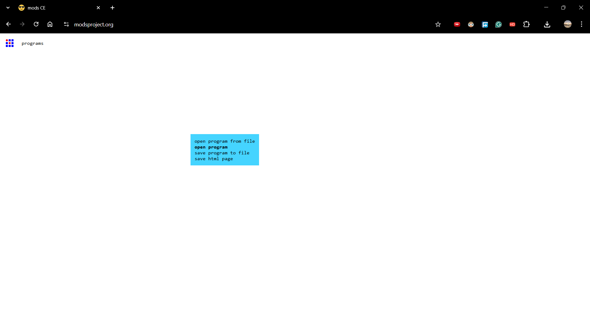
Program
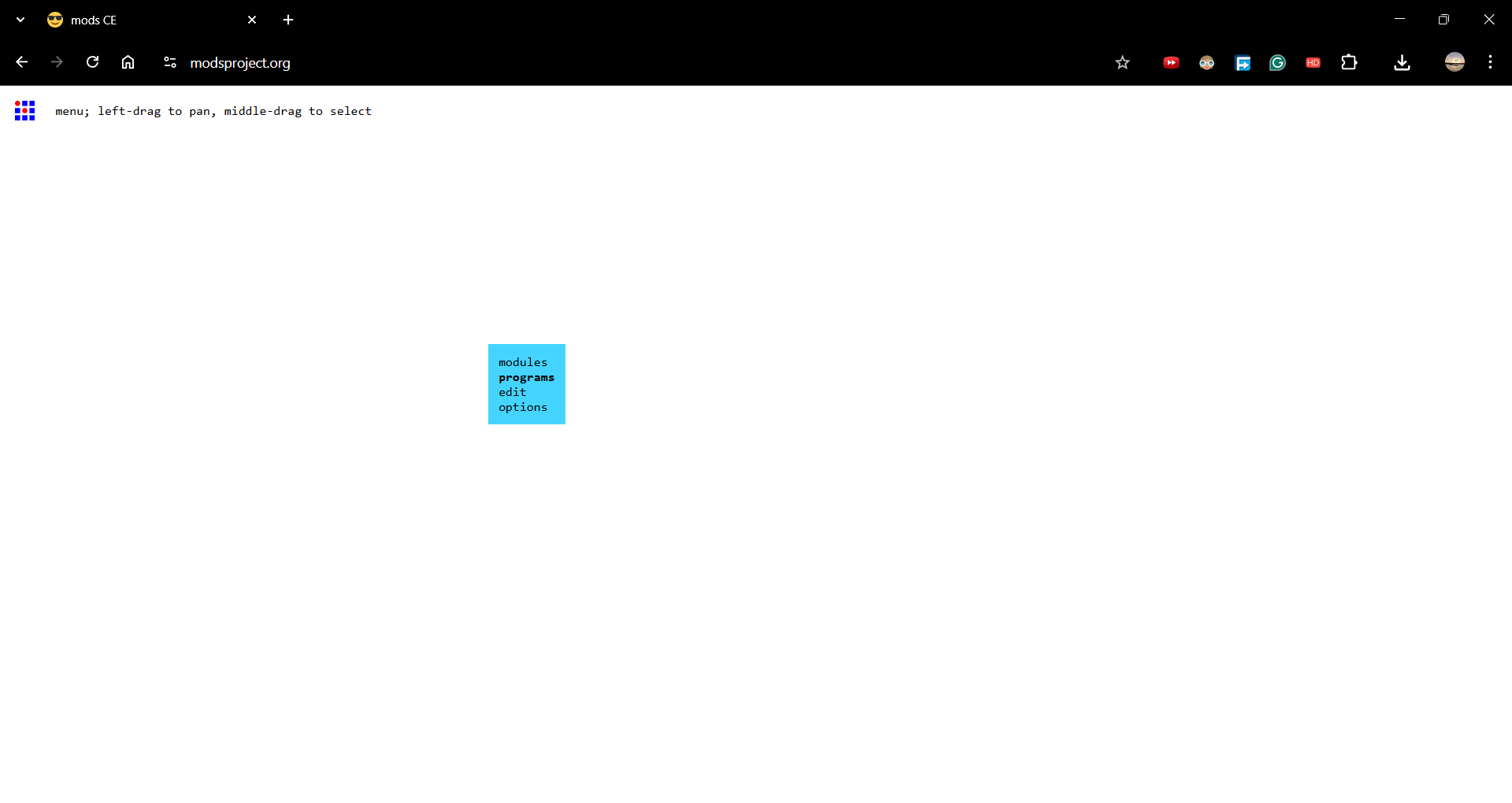
Then I clicked on Open Program.
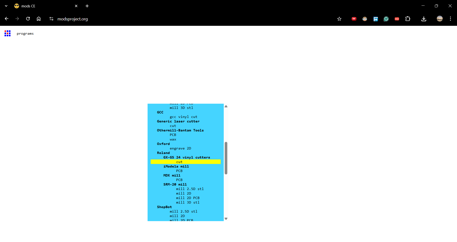
Machine and Process Selection#
From the available options, I selected:
- Roland as the machine
- Chose the appropriate machine model
- Selected Cut as the process
Loading File and Cutting#
Next steps:
- Loaded the SVG file
- Clicked Calculate to generate toolpaths
- Performed a test cut to verify blade depth and force
- Sent the file to the vinyl cutter for final cutting
The cutting process completed successfully after verifying the test cut, and the final vinyl output was obtained.
Vinyl Cutting Process:
Final output after cutting: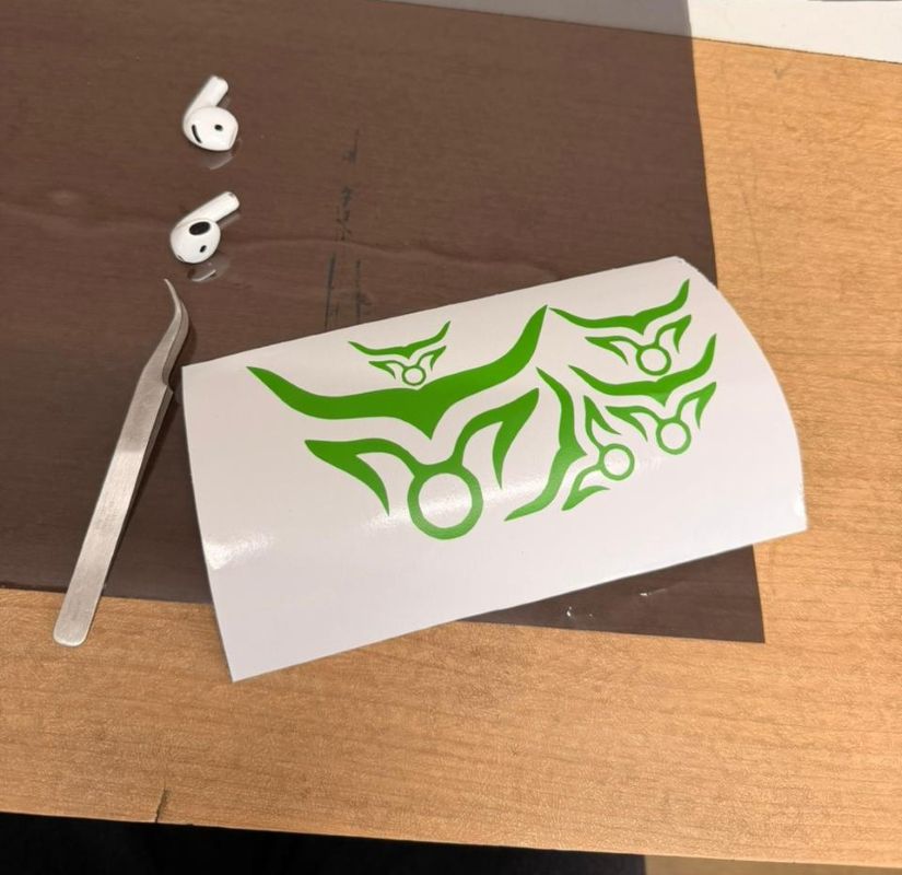
Transfer paper was applied so the stickers could be mounted easily: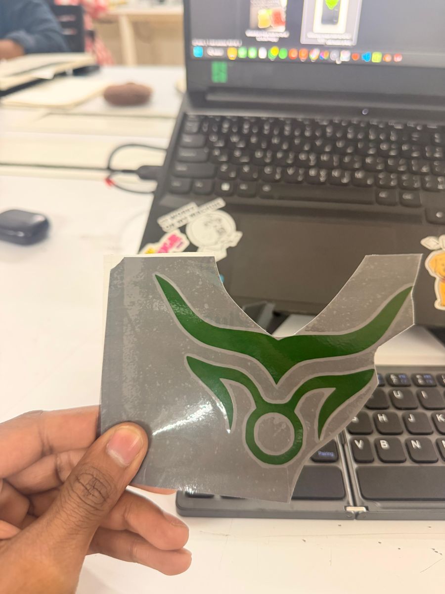
Final hero shots: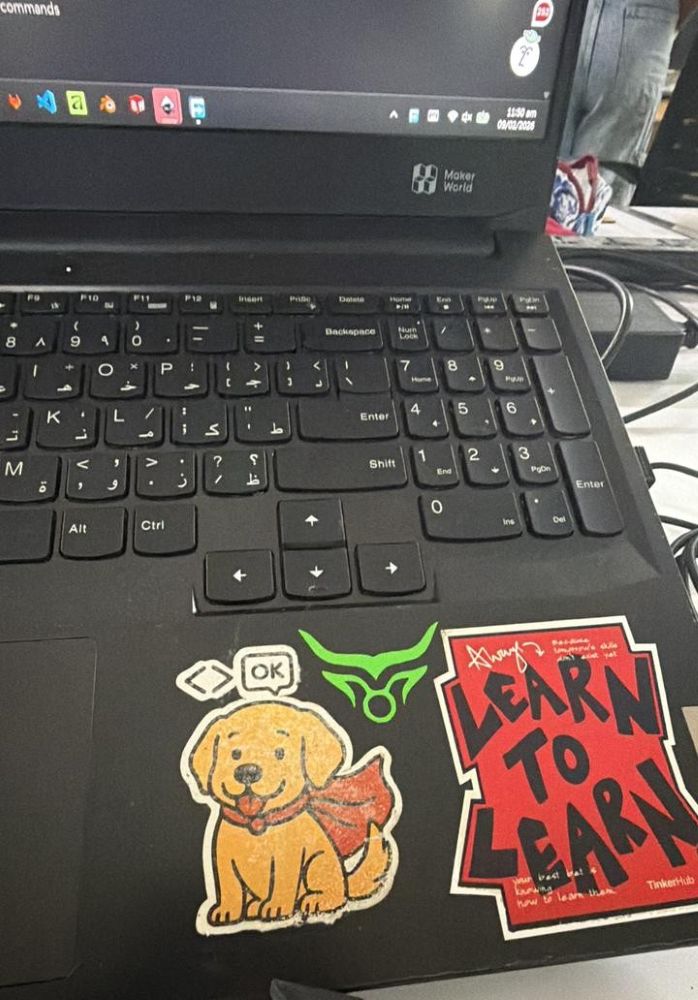
Laser Cutting#
Machine Used#
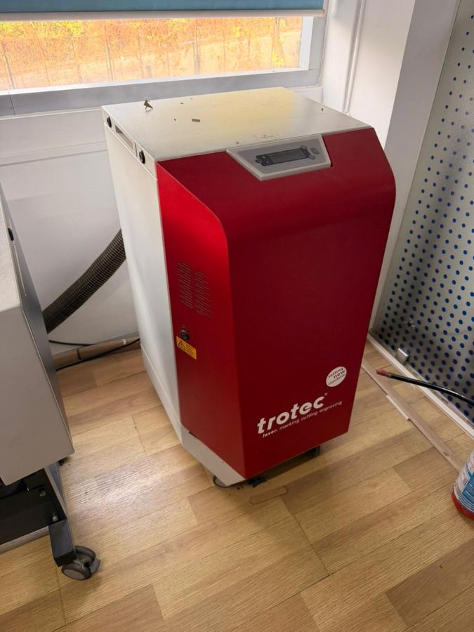
Trotec Speedy 100 – Laser Cutter & Engraver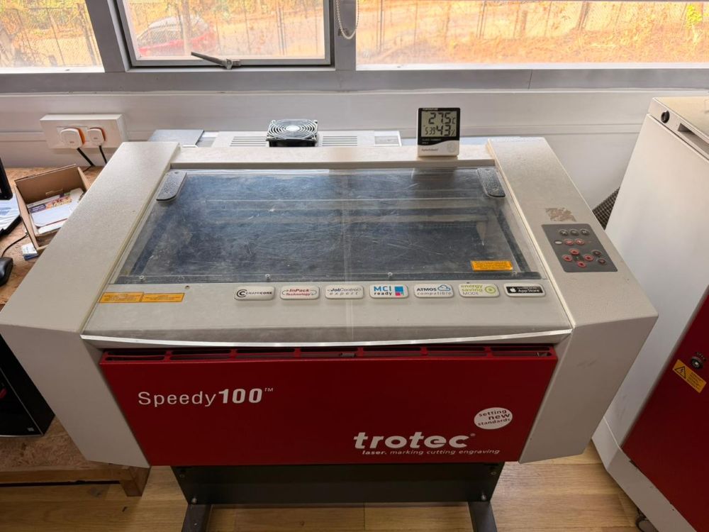
A laser cutter is a computer-controlled machine that uses a focused laser beam to cut, engrave, or mark materials such as wood, acrylic, paper, leather, and certain plastics with high precision.
Buy / Product link:
https://www.troteclaser.com/en/laser-machines/laser-engravers-speedy-series
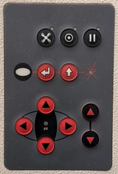
Machine Controls#
- Laser power (%)
- Cutting speed (mm/s)
- Frequency / PPI
- Focus height
- Air assist and exhaust control
- Job origin and alignment
Setup Process#
- Place material on the cutting bed (honeycomb or flat bed).
- Adjust focus using the focus tool or autofocus.
- Set origin (usually top-left or center).
- Select material preset or manually set power & speed.
- Run a small test cut.
- Start full job and monitor cutting.
- Turn on exhaust and air assist during operation.
Materials Commonly Used#
- Plywood / MDF
- Acrylic (PMMA)
- Cardboard
- Leather
- Paper
- Fabric
⚠️ Do NOT cut PVC or vinyl — toxic chlorine gas is released.
Parametric Designing#
This week’s individual assignment was to design a parametric construction kit that could be laser cut and assembled.
The design had to account for laser kerf to ensure proper fit and function.
Things to consider from group assignment:
- Kerf - 0.3mm
- Material thickness - 3mm cardboard
- Press fit joints - 0.2mm clearance
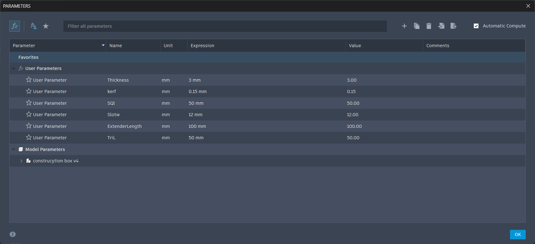
Parametric Construction Kit#
For the construction kit, I followed the same parametric workflow as the kerf comb.
The idea was to design 10 different parts that together form a universal construction kit.
The design was fully parametric so it could adapt to:
- Different material thicknesses
- Different materials
- Different laser kerf values
Parametric Construction Kit – Detailed Workflow#
Steps followed:
Opened Fusion 360 and set up all required parameters for the construction kit
Modeled all 10 individual components using parametric sketches
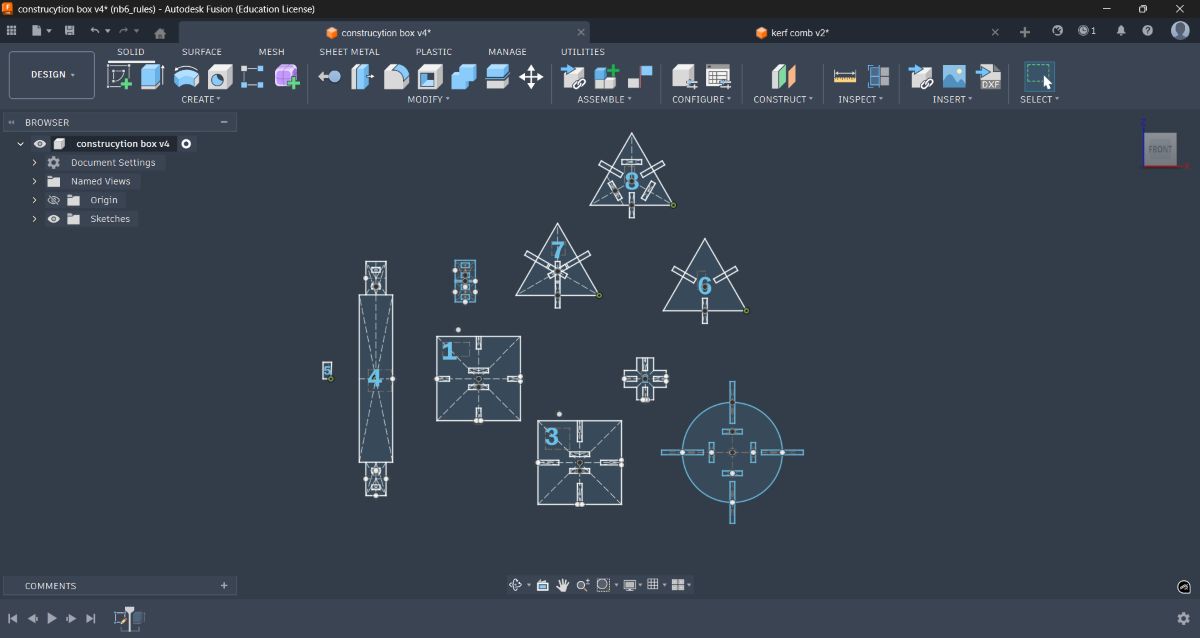
Extruded the components and added chamfers to the press-fit edges to improve fit
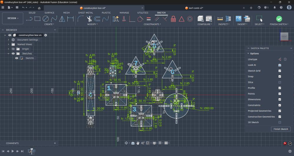
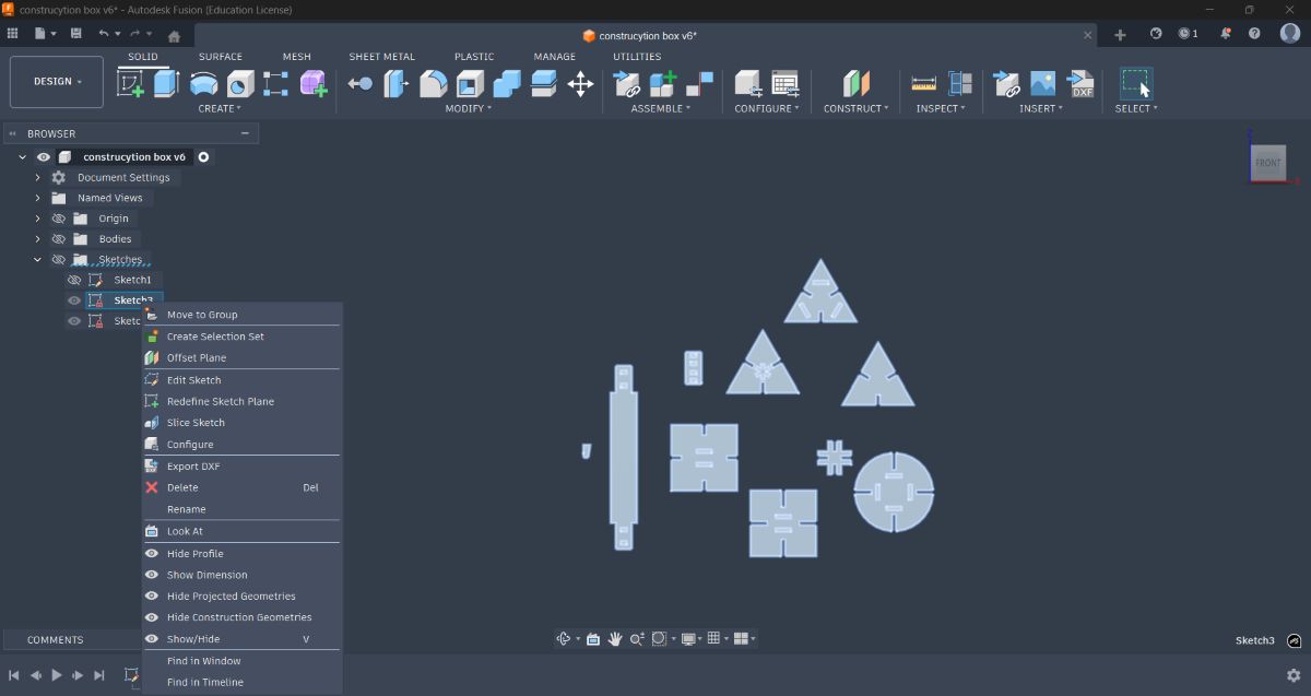
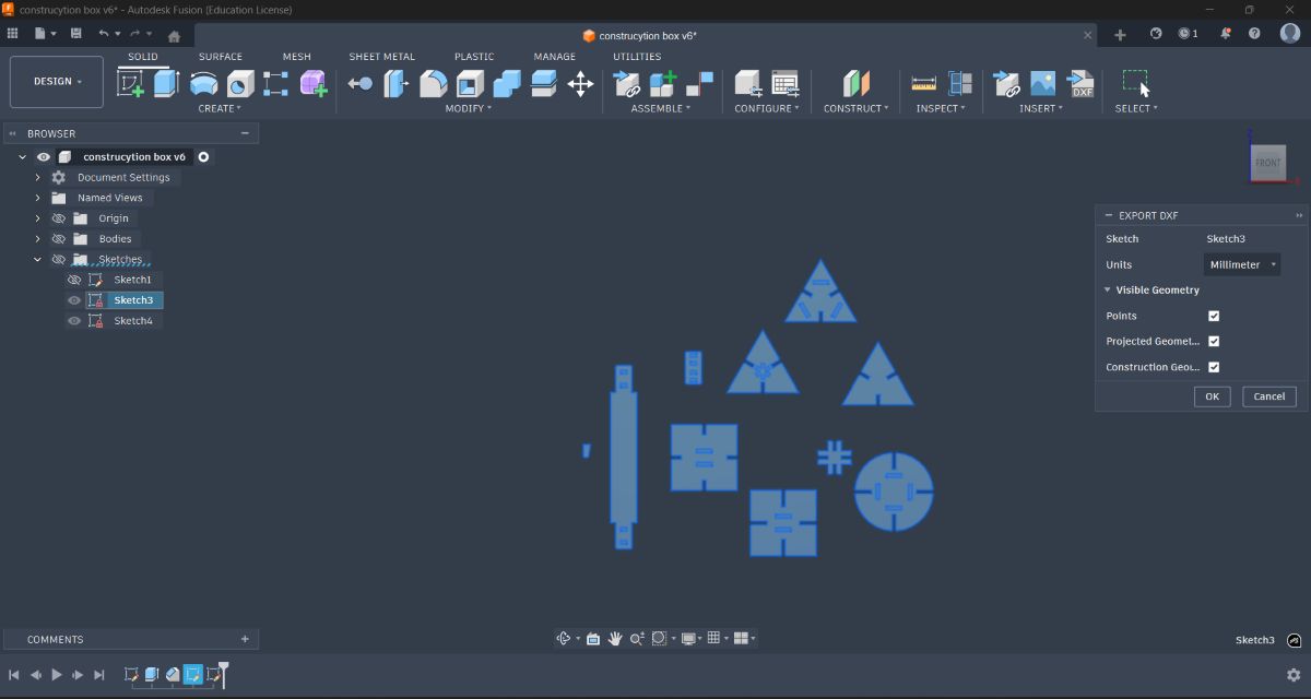
Projected the geometry onto a new sketch and prepared it for export
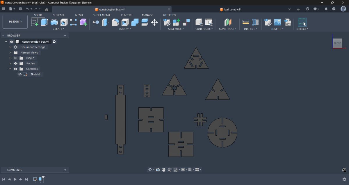
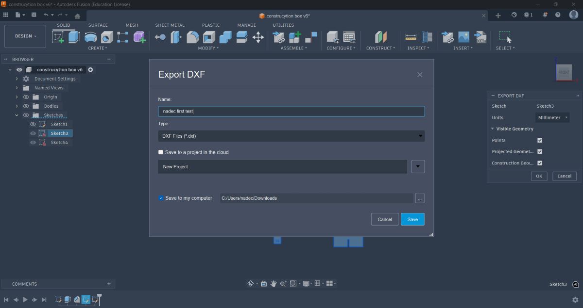
Exported the sketches as DXF files
Preparing the DXF in Inkscape#
Imported the exported DXF into Inkscape
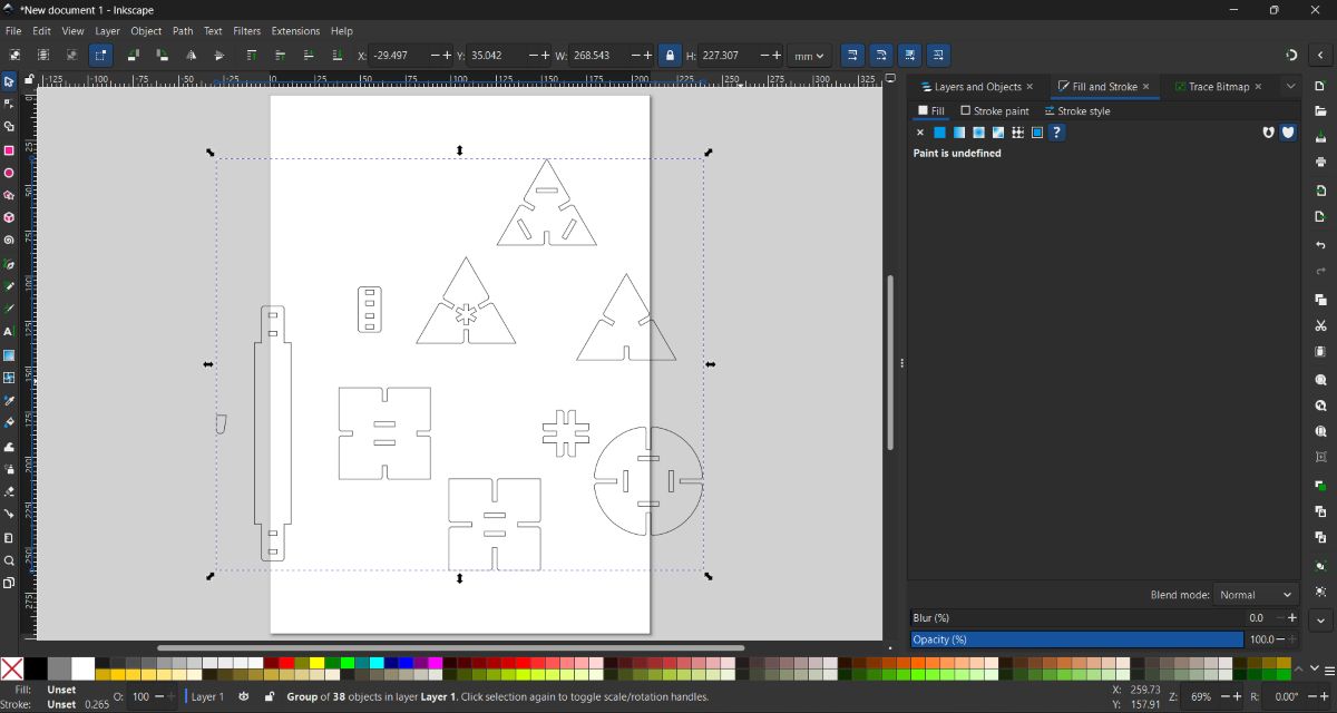
Ungrouped all parts using Ctrl + Shift + G, rearranged them, and grouped them back using Ctrl + G
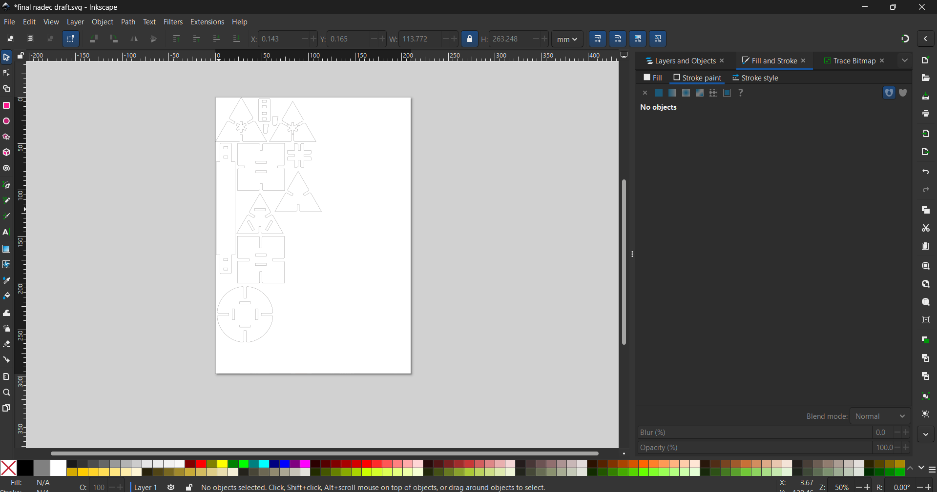
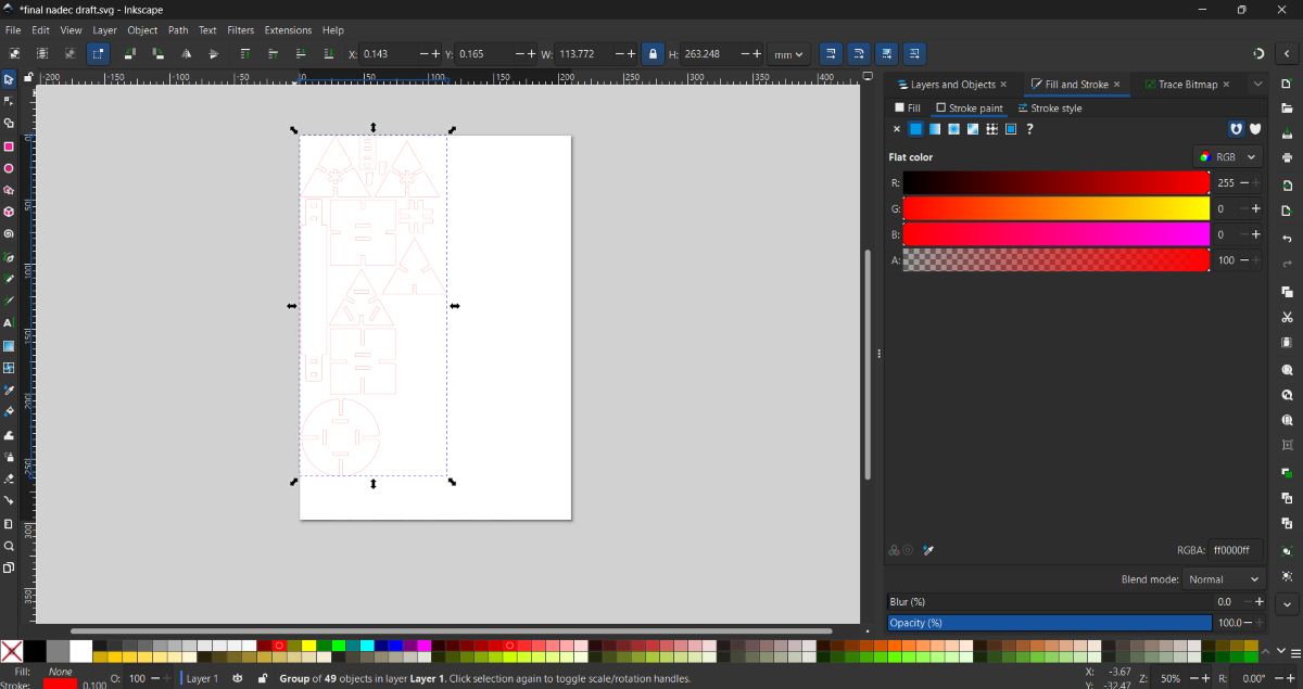
Selected all objects (Ctrl + A) and set:
- Fill: No fill
- Stroke color: Red
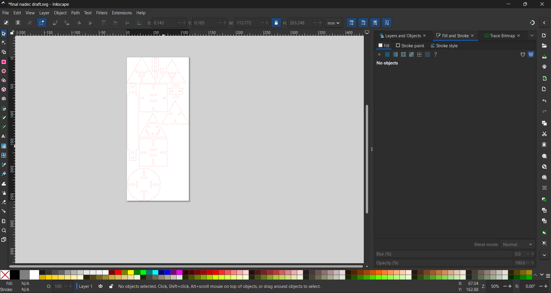
Resized the canvas to fit the objects using Ctrl + Shift + R
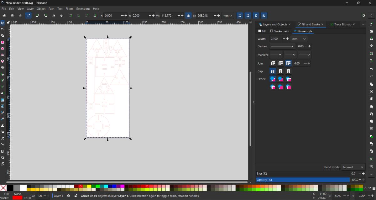
Selected all objects again and set the stroke width to 0.1 mm in Stroke Style
Nesting Using Deepnest#
Exported the file and opened it in Deepnest for nesting
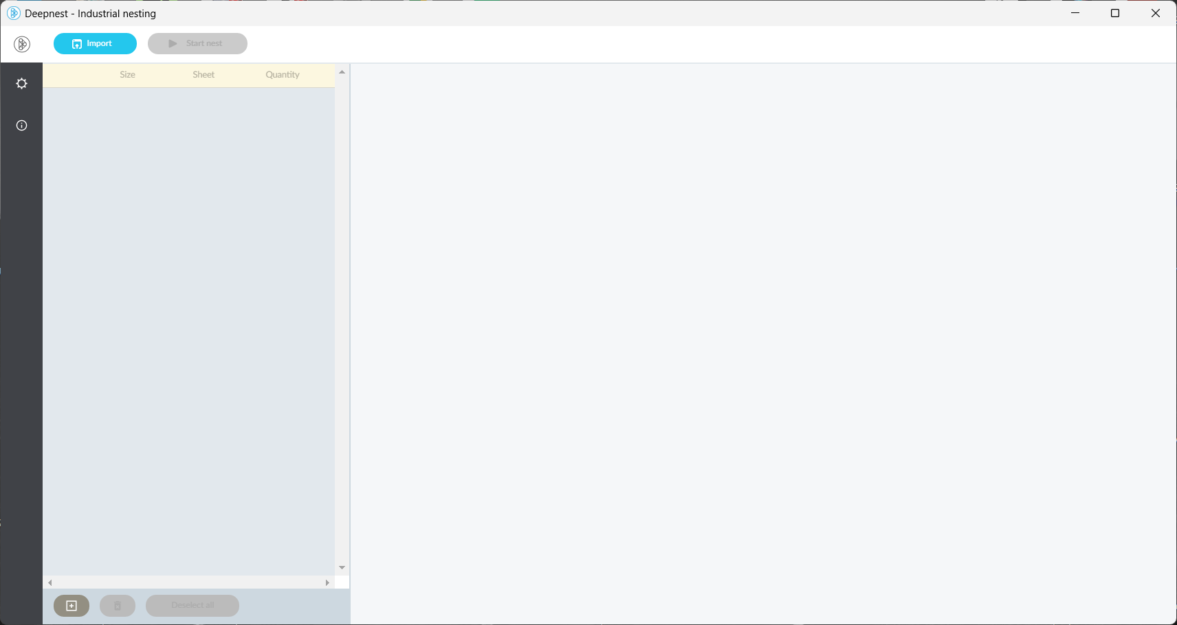
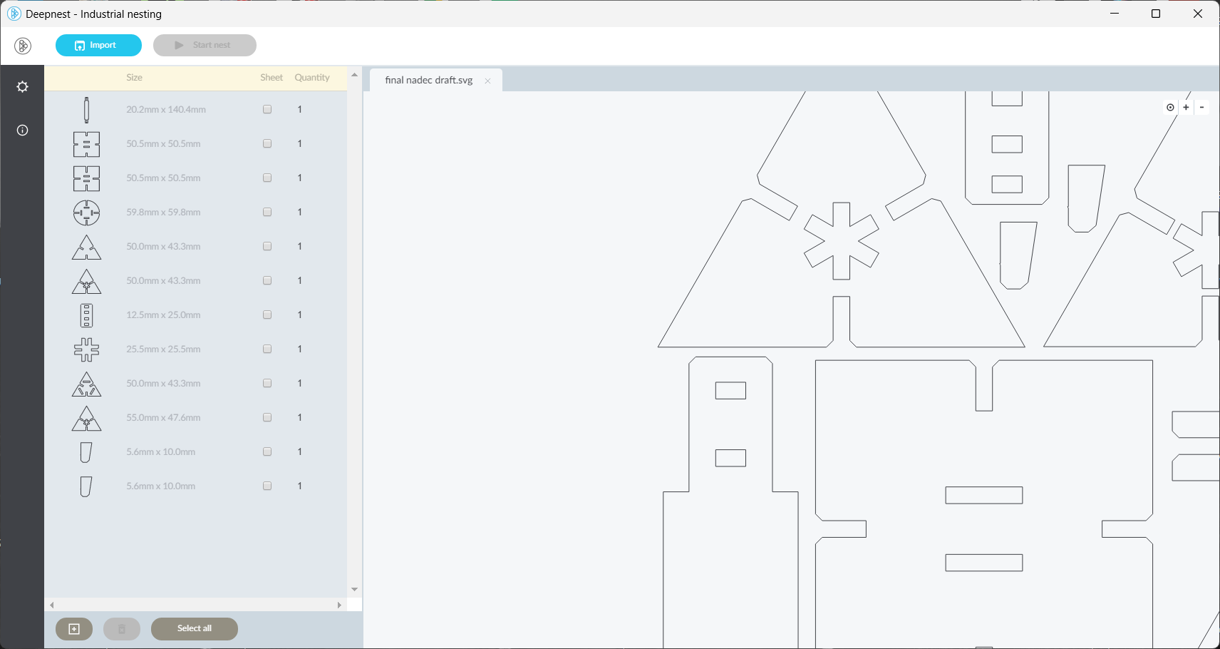
Added the sheet size corresponding to the cardboard used
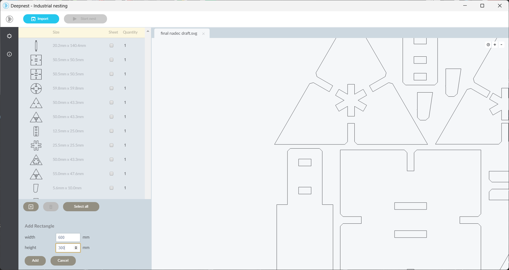
Set the required quantity for the construction kit parts
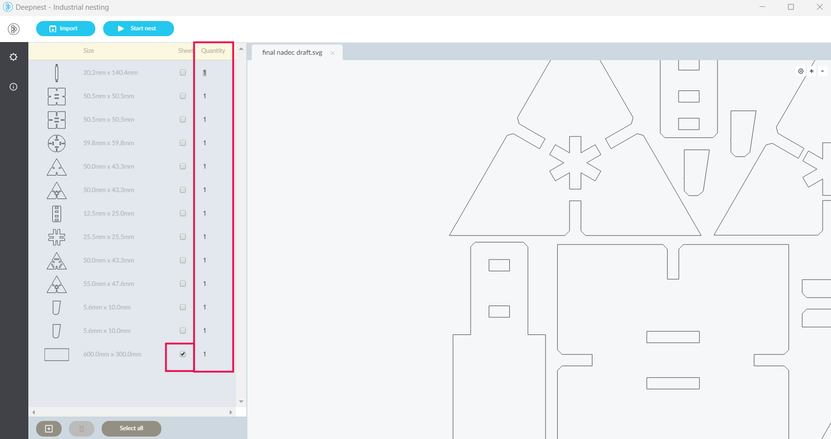
Started the nesting process to optimize material usage
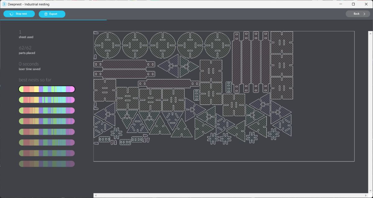
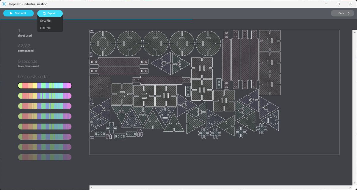
After nesting was completed, exported the file as an SVG
Laser Cutting#
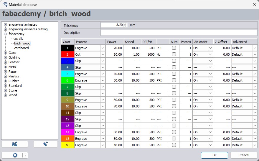
Imported the nested SVG into Trotec Job Control and set the required power and speed values
Started the laser cutting process
Laser Cutting Process:
Final Output#
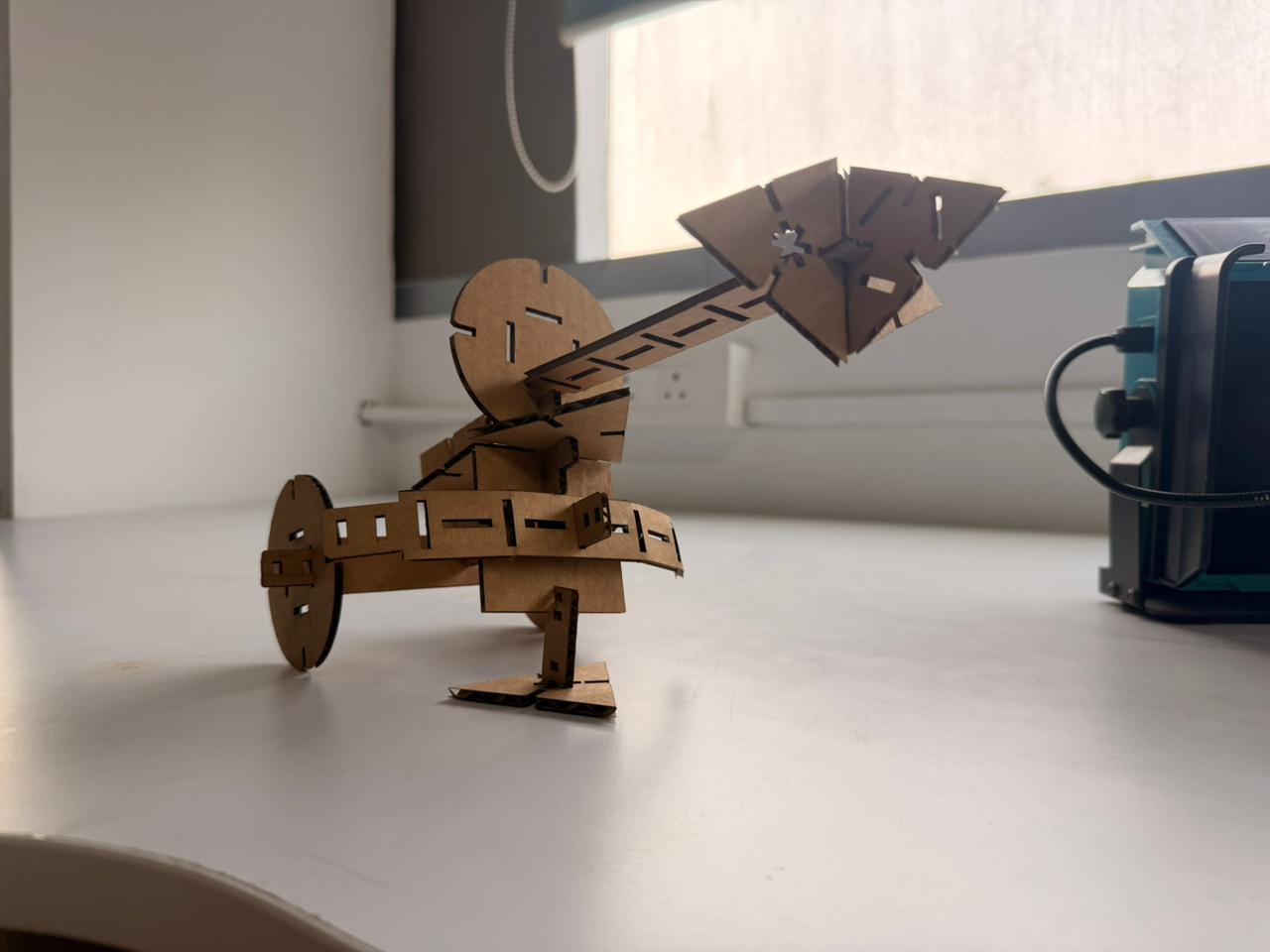
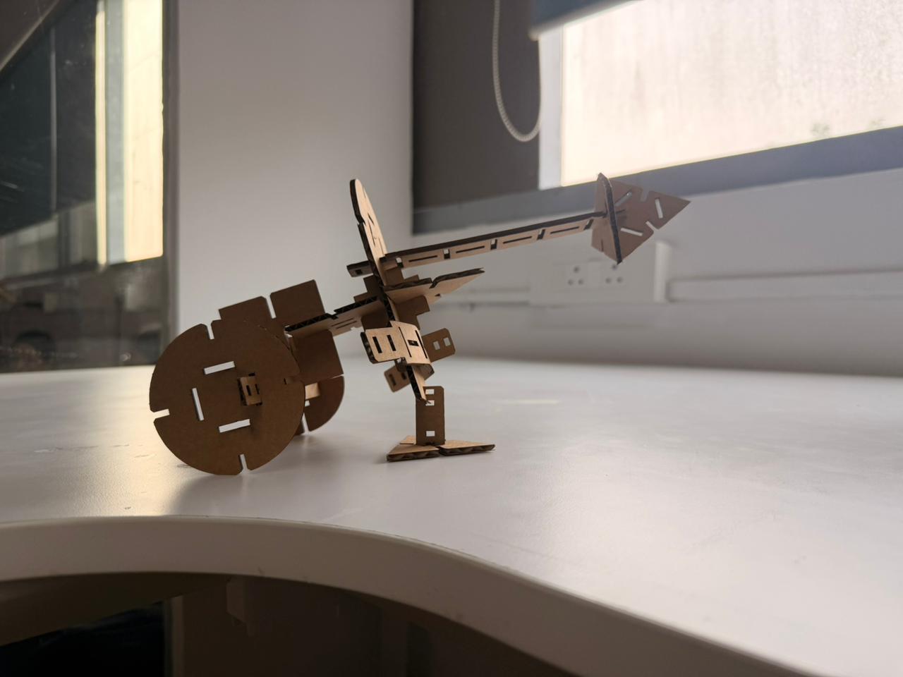
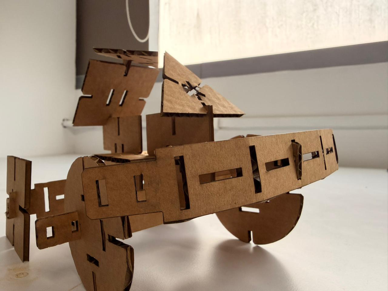
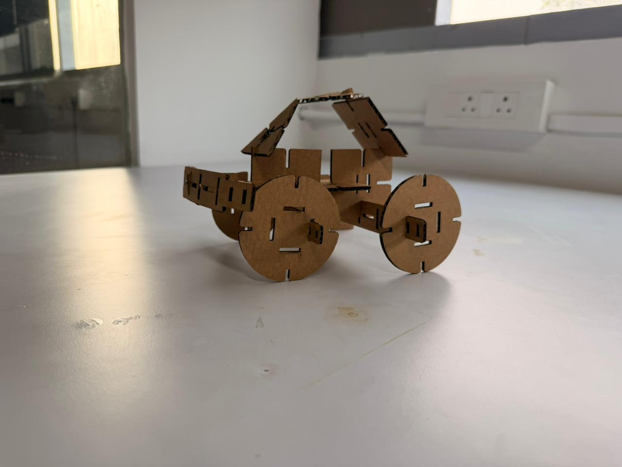
Hero shot of the completed construction kit: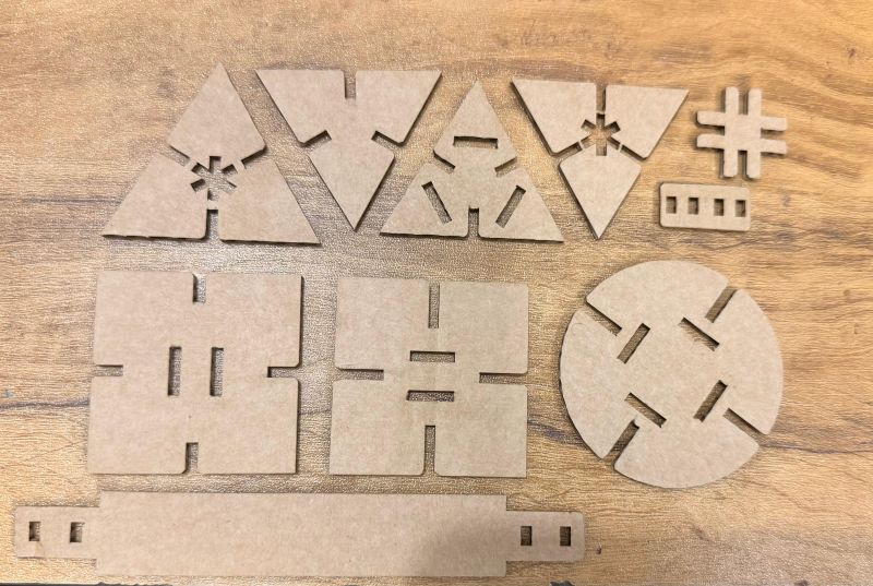
Hero shots of the assembled construction kit:
Take a look at what i had build

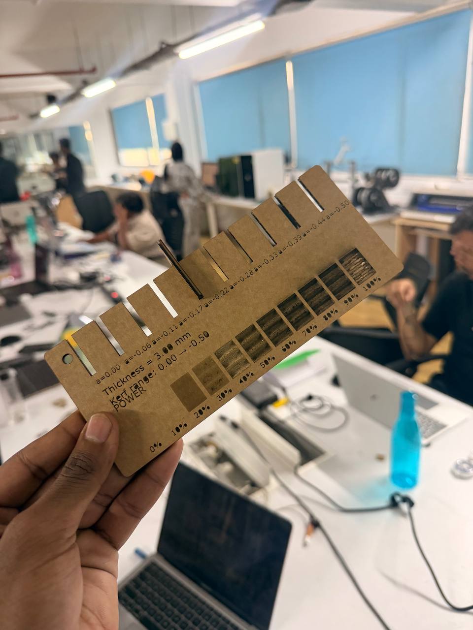
Compression Testing Comb (Fusion 360)#
My first design task this week was creating a compression testing comb as part of the group-related work.
I flipped a coin between SolidWorks and Fusion 360, and Fusion 360 won.
Workflow:
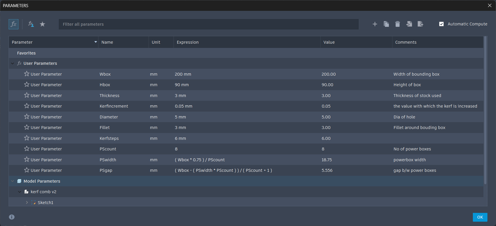
- Opened Fusion 360 and opened the parameters tab
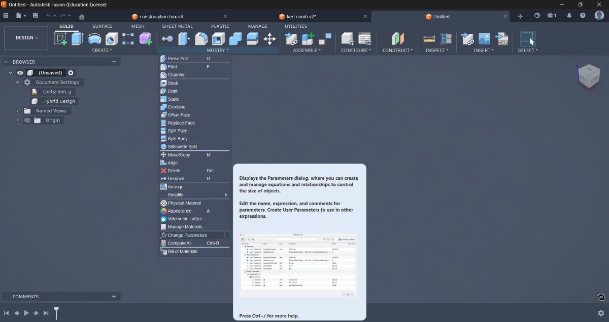
- Defined all required parameters for the kerf gauge
- Modeled the entire sketch
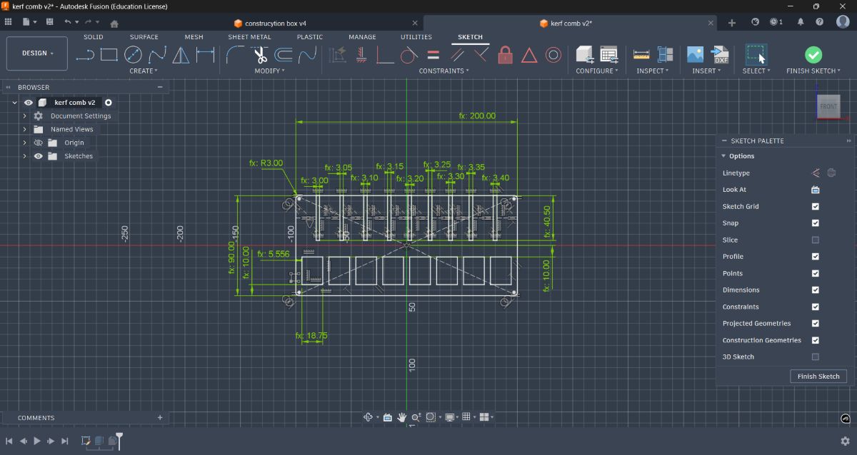
- Extruded the sketch
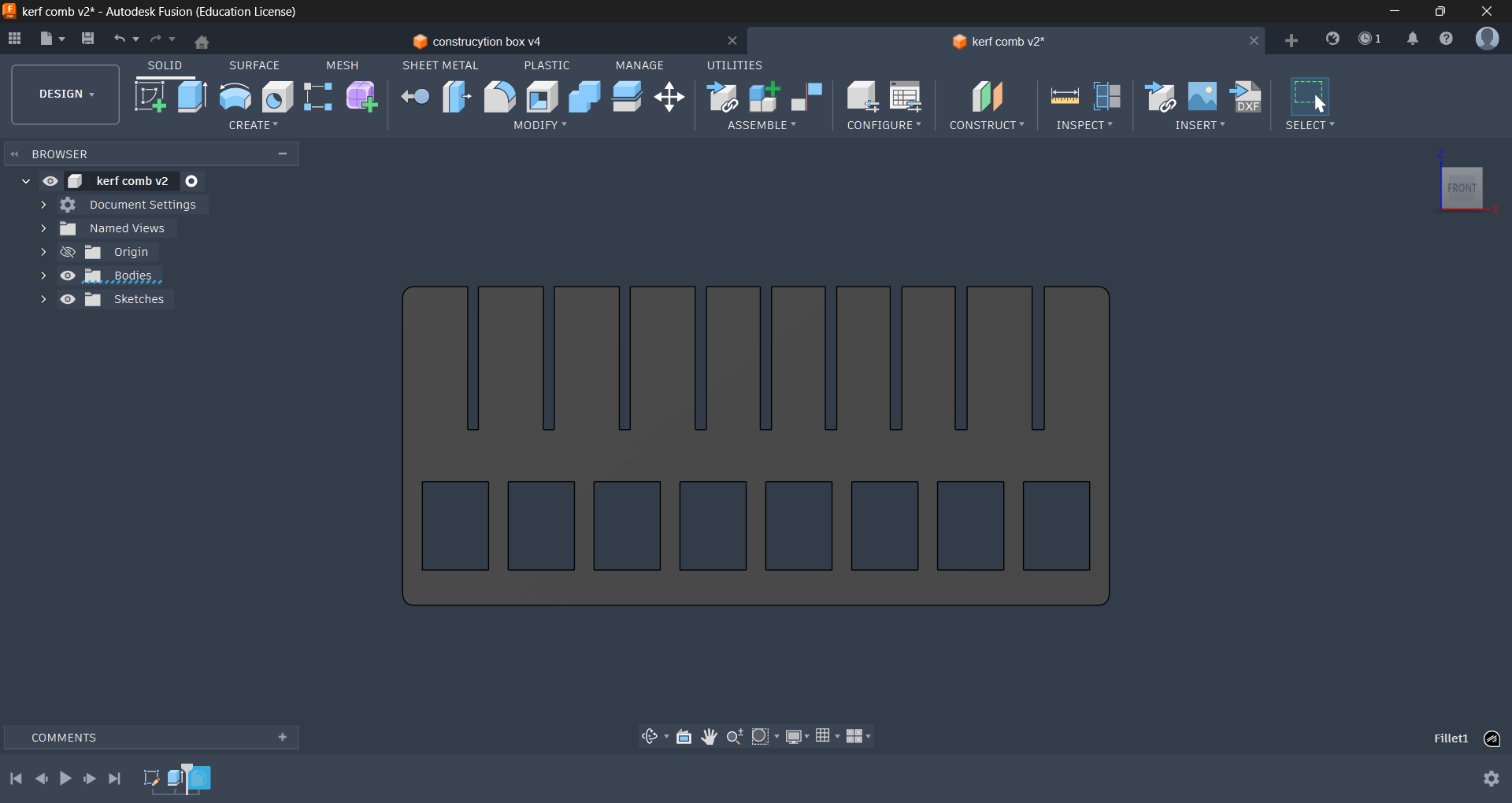
- Applied fillets where needed
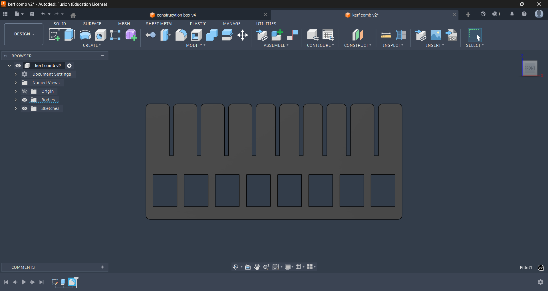
- Created a new sketch
- Projected the extruded shape onto the sketch
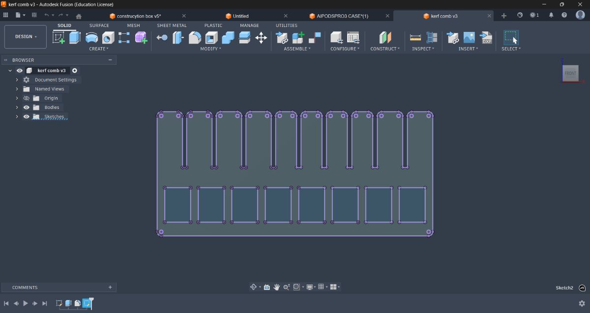
- Exported the sketch as DXF
- Opened the DXF in Inkscape
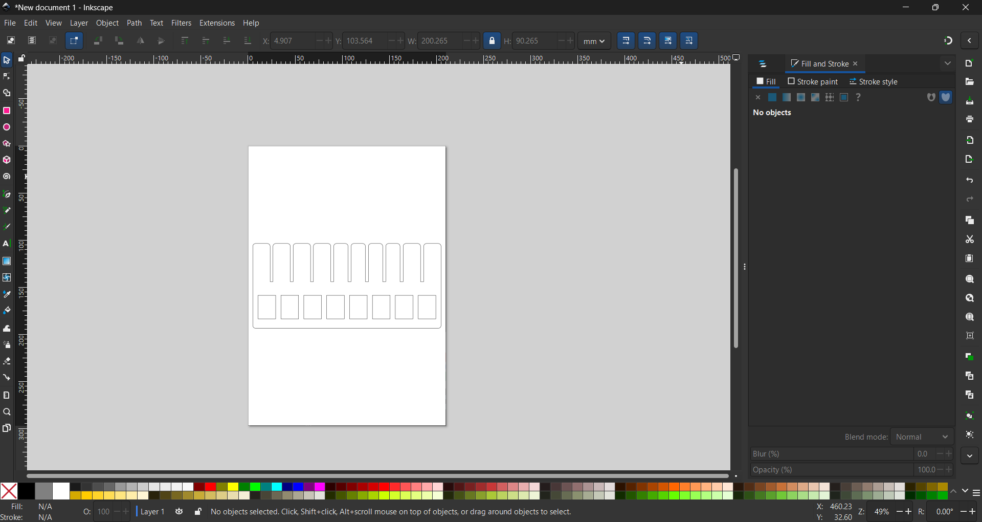
In Inkscape, I ensured:
- All cut paths were strokes
- Engraving areas were fills
I then sent the file to the Trotec laser cutter, adjusted power and speed values in the Job Control software, and completed the cut and engraving.
Making a Laser Cut Layered Statue#
After completing the assignments for the week, I planned to make something additional — a laser-cut layered statue.
The idea was to create a 3D model composed of multiple 2D laser-cut layers stacked together, similar in concept to how a 3D printer builds objects layer by layer.
Step 1 – Generating the 3D Model#
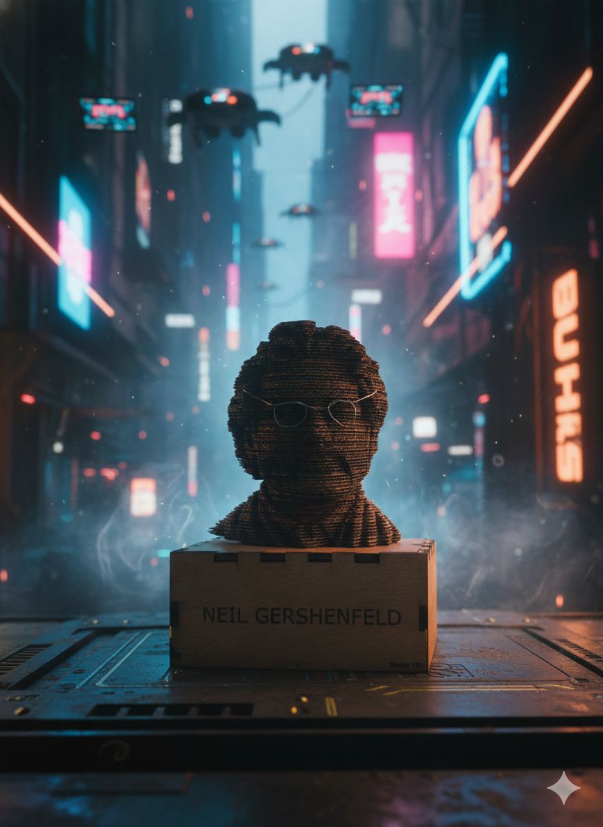
First, I needed a 3D model. I thought it would be interesting to make a statue of Neil.
I searched online and found a suitable image of him.
Then I opened Bambu Studio, navigated to the Maker Lab section, and selected the “Make My Statue” option. I uploaded the image of Neil into the tool.
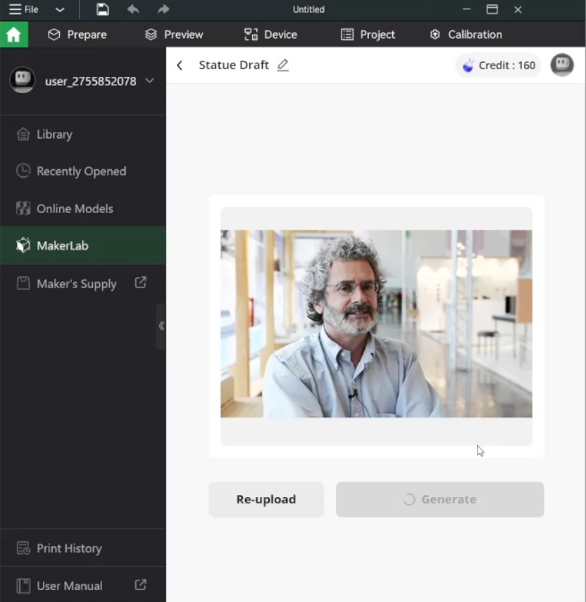
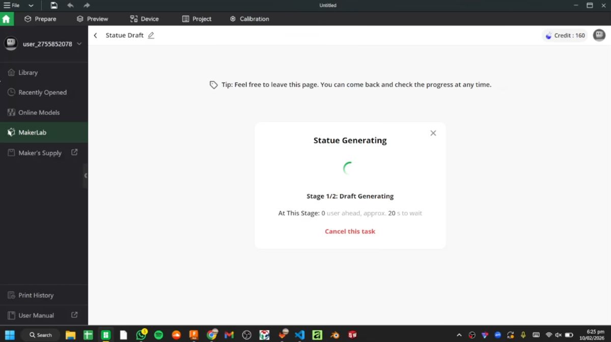
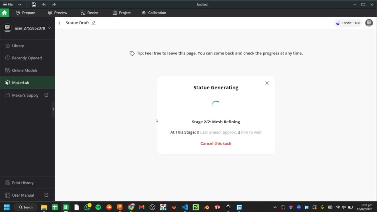
The software then began processing the image into a 3D model.
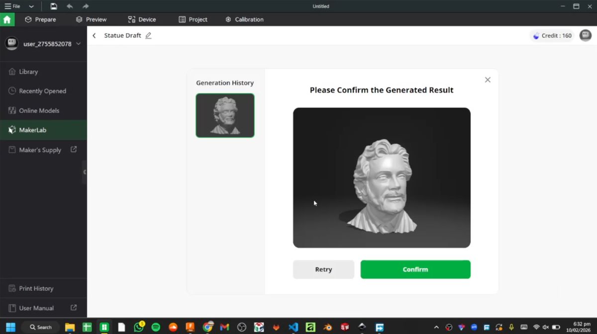
After processing, it generated a rendered 3D output, which I exported as an STL file.
Step 2 – Modifying the Model in 3D Builder#
Next, I imported the STL file into 3D Builder (which I had previously used in Week 2).
To allow structural support during assembly, I created:
- Two cylinders
- 200 mm height
- 8 mm diameter
These were positioned inside the model.
Then I performed a Boolean subtraction to remove the volume of the cylinders from the statue. This created two internal holes that would later allow threaded rods to pass through and hold the stacked layers together.
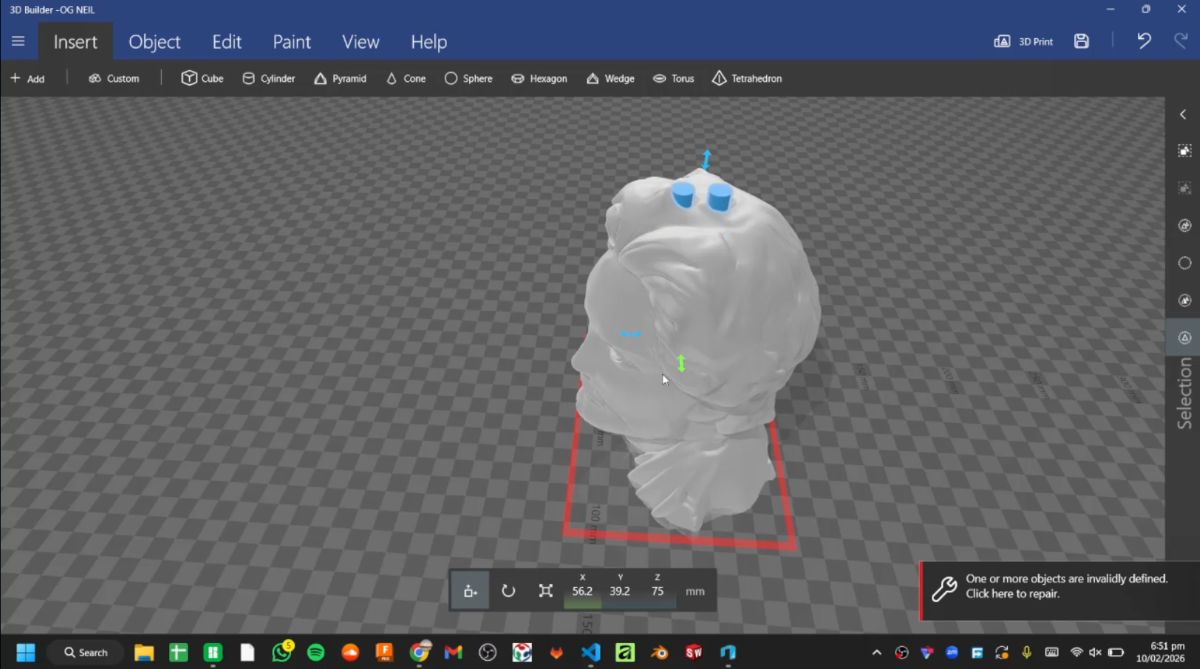
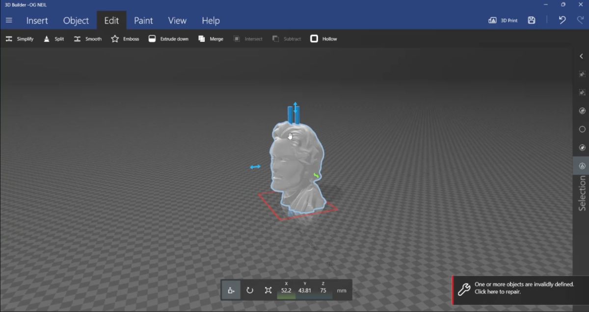
After completing this modification, I saved the updated STL file.
Step 3 – Slicing for Laser Cutting (Kiri:Moto)#
I then imported the modified STL into Kiri:Moto and switched to Laser Mode.
Material used:
- 2 mm thick cardboard
- Kerf value set to 0.3 mm
After entering the material thickness and kerf values, I sliced the model into layers.
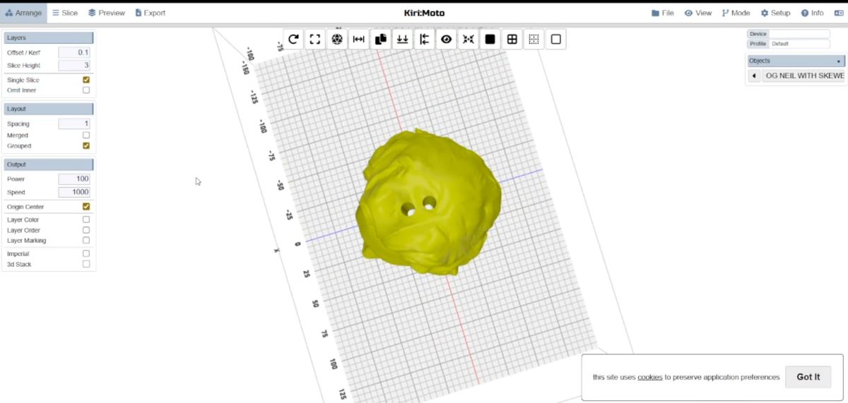
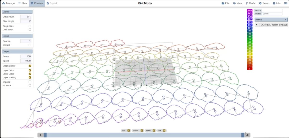
The slices were exported as SVG files.
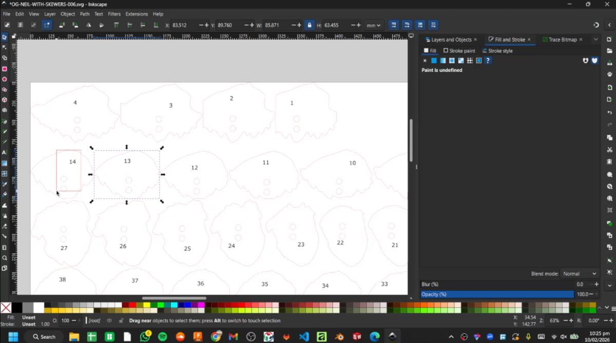
Step 4 – Organizing Layers in Inkscape#
The exported SVG files were opened in Inkscape.
To make assembly easier, I labeled the individual layers numerically (1, 2, 3… up to 78).
This numbering system helped during stacking and alignment.
Step 5 – Nesting in Deepnest#
The labeled SVG files were then imported into Deepnest for nesting.
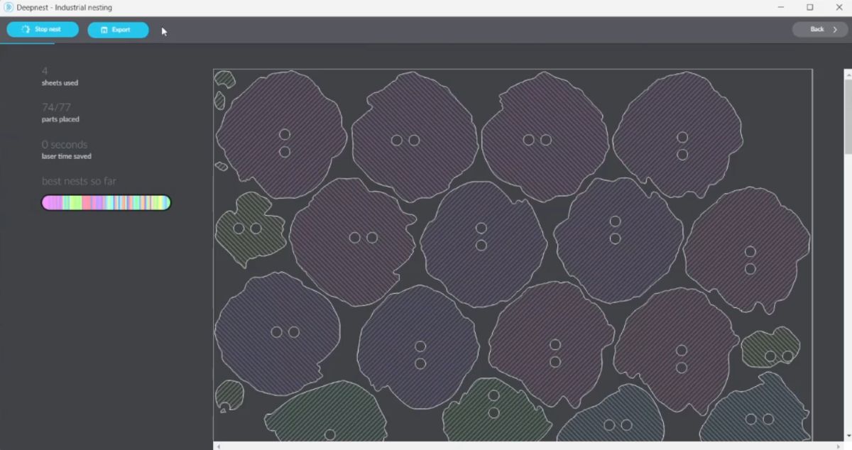
After nesting was completed, the optimized layout files were exported.
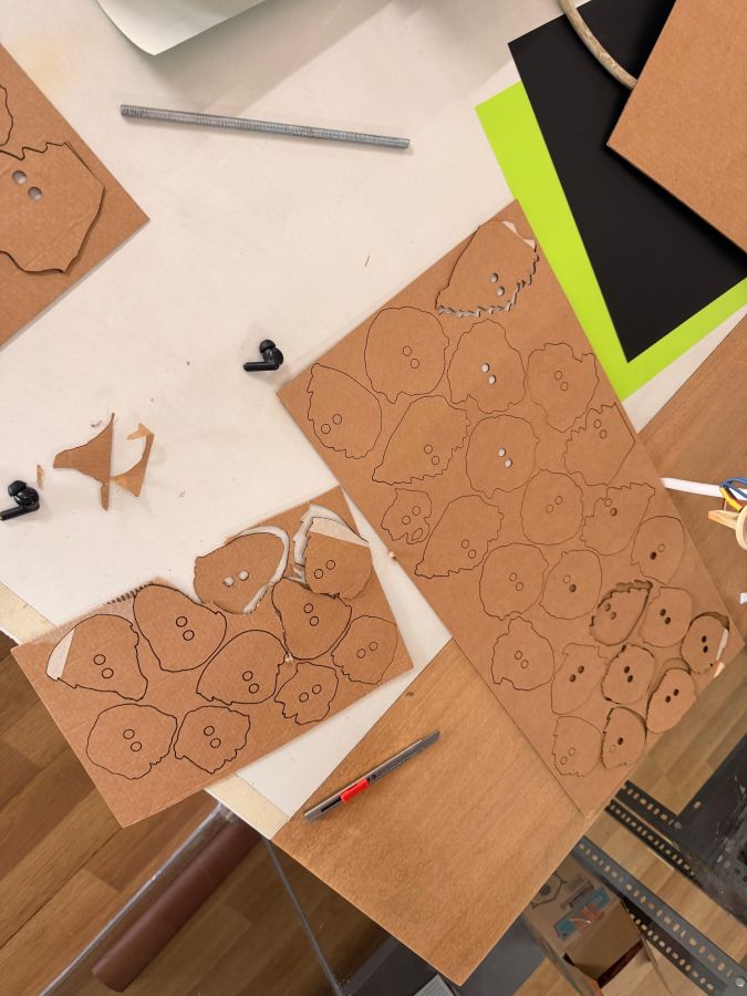
Step 6 – Laser Cutting#
The nested SVG file was opened in Trotec Job Control.
The 2 mm cardboard sheet was placed on the laser bed, and appropriate power and speed values were set.
The cutting process was then started.
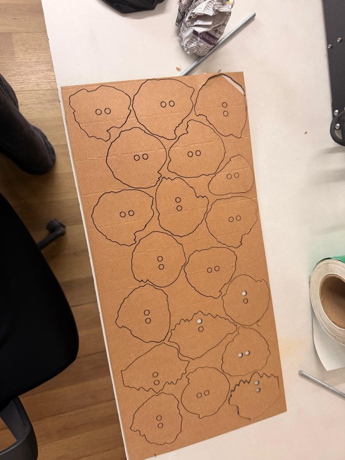
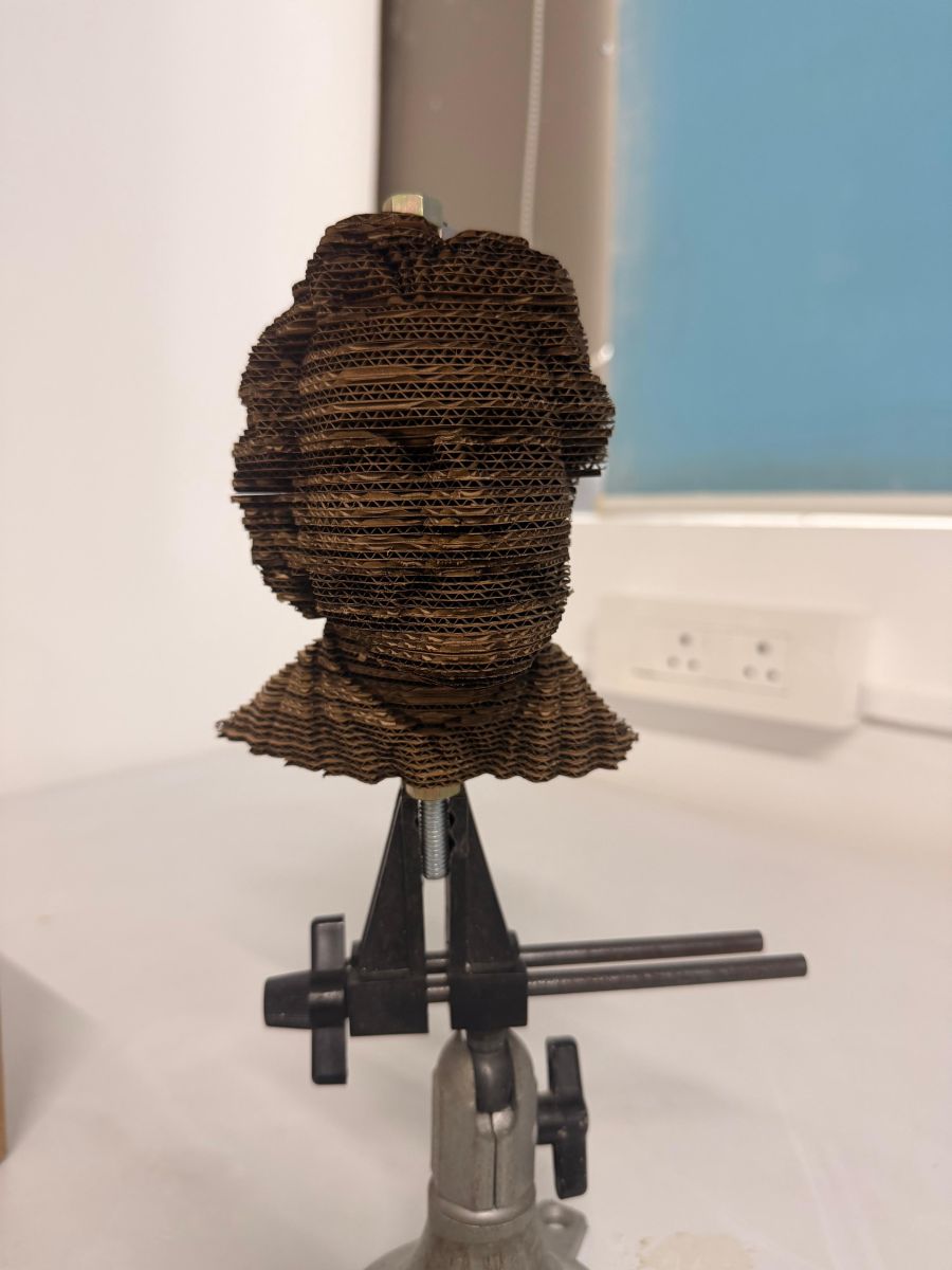
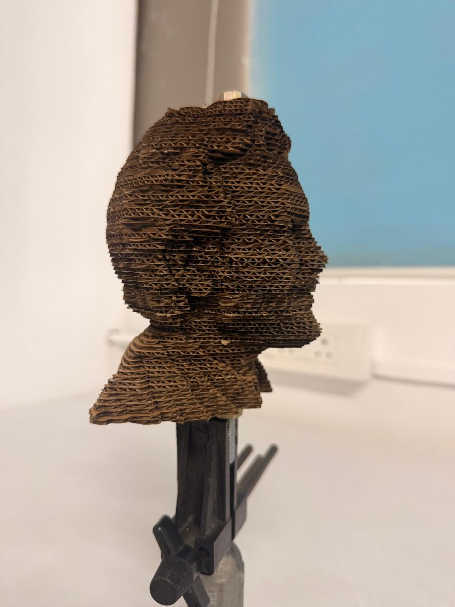
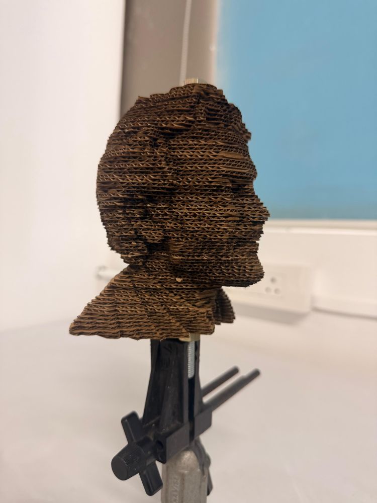
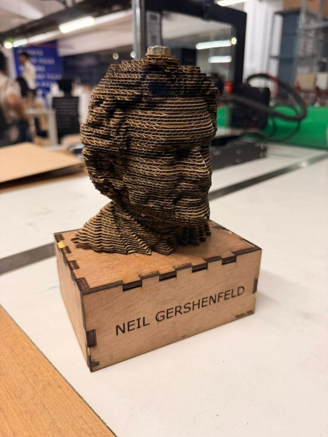
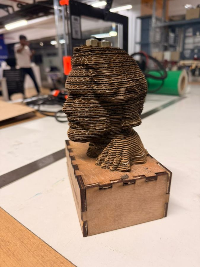
Final Assembly – Hero Shots#
After cutting all the layers, the pieces were stacked in order and aligned using the threaded rods inserted through the internal holes.
Final assembled layered statue:
Creating the Base for the Statue#
The next step was designing and fabricating the base for the layered statue.
First, I measured the required dimensions for the box that would hold and support the statue. Based on those dimensions, I used the following parametric box generator:
🔗 https://cuttle.xyz/@cuttle/Open-Box-with-Finger-Joints-D2ugGEvYUNfd
Using this tool, I entered:
- Required length
- Width
- Height
- Material thickness
The tool automatically generated an open box with finger joints, which was suitable for laser cutting.
After generating the box layout, I exported the design as an SVG file.
Editing in Inkscape#
The exported SVG was opened in Inkscape, where:
- I added the required text on the base
- Ensured all cut paths were strokes
- Verified stroke width was suitable for laser cutting
Once the design was finalized, the file was sent to the Trotec laser cutter.
Laser Cutting and Assembly#
The box parts were laser cut from cardboard using the appropriate power and speed settings.
After cutting:
- The finger joints were aligned
- The box was assembled manually
- The statue was mounted onto the base
Final Base + Statue – Hero Shots#
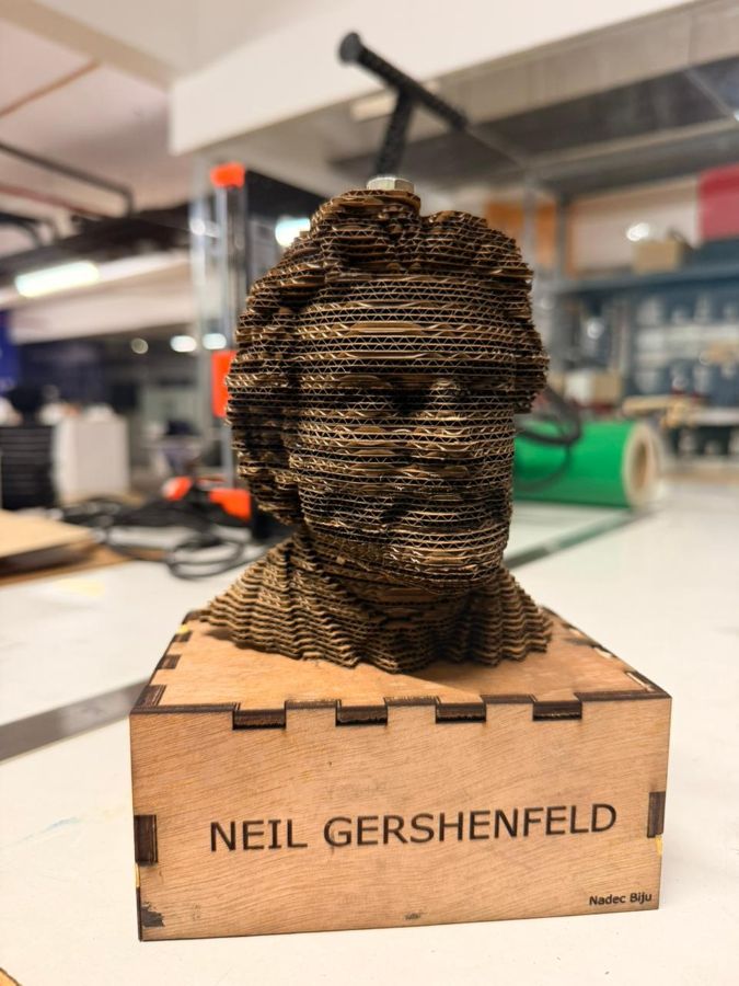
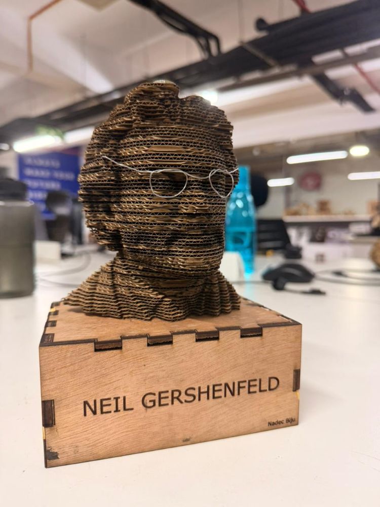
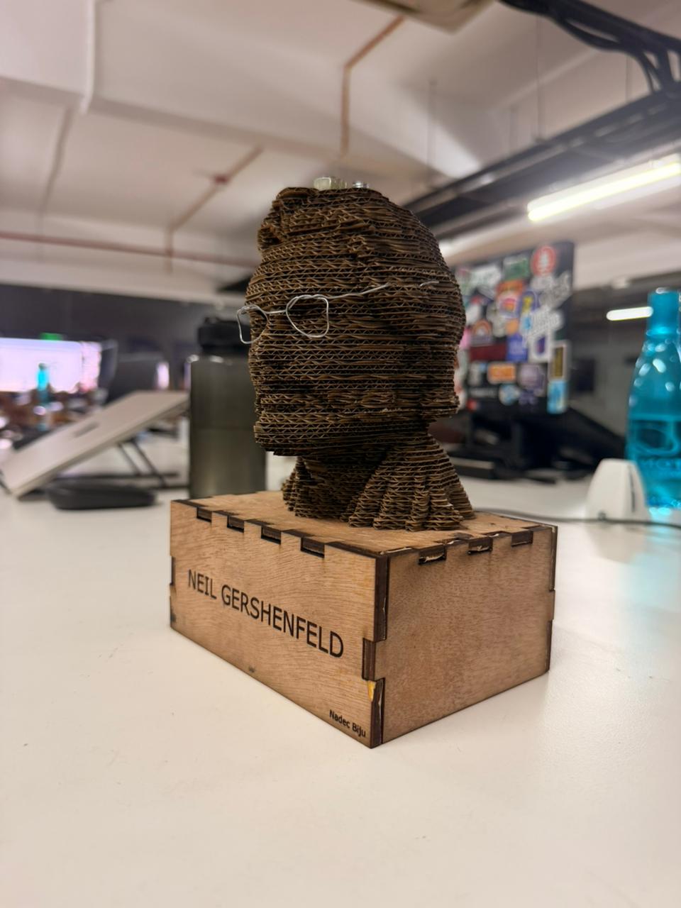
Wait a second… something was missing — THE GLASSES 😤👓#
So instead of redesigning anything fancy, I just bent some solder wire and made the glasses manually and attached them to the statue 😌🔥
Final Reflection#
This week made it very clear that designing is only half the job.
Understanding machine behavior, safety, kerf, and material limitations is just as important.
Week 3 successfully bridged the gap between digital design and physical fabrication.