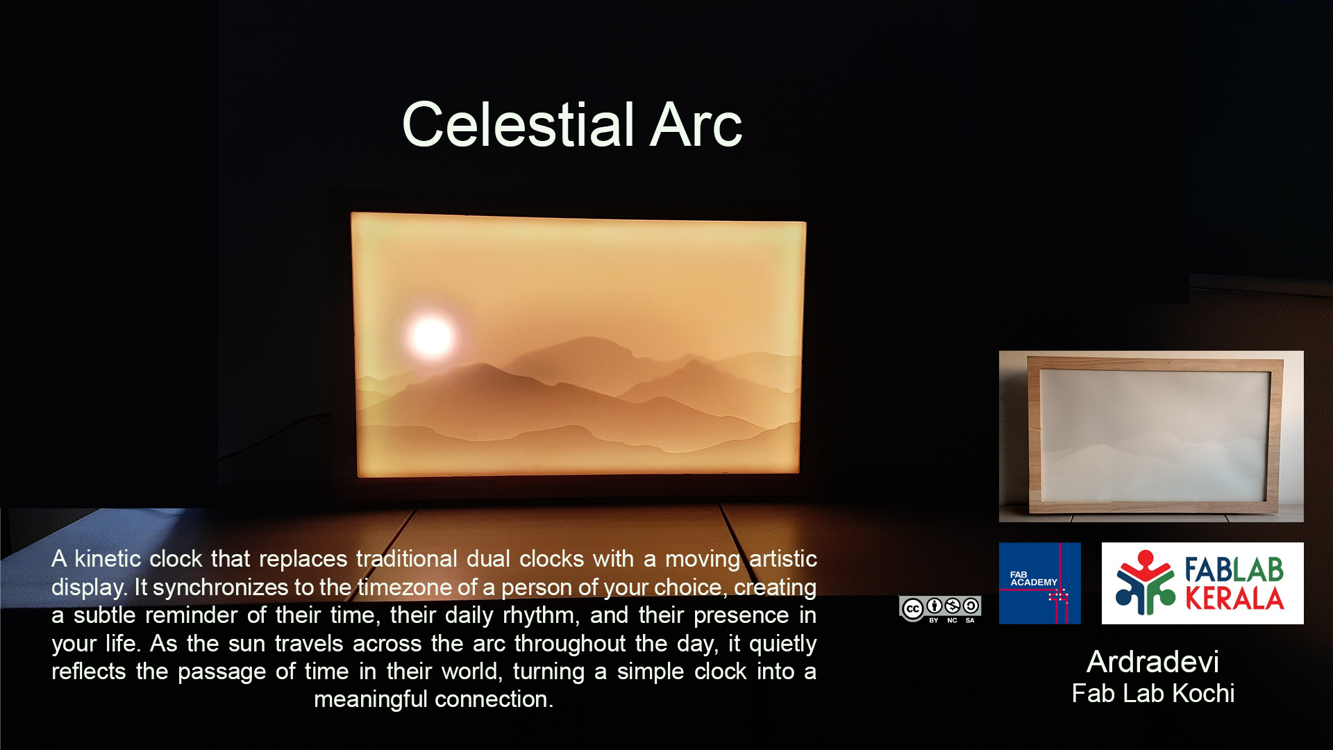
Celestial Arc
An artistic dual clock connecting lives across time
Final Presentation Slide
Final Presentation Video
A brief introduction
Celestial Arc is a kinetic dual time zone clock that transforms timekeeping into an artistic experience. It is both a functional timepiece and a wall décor piece. Celestial Arc allows users to keep track of the time of a friend or loved one living in another part of the world. During the day, the glowing ring acts as the sun, gradually travelling along an arc to represent the passage of time. At night, it transitions into the moon, creating a dynamic and calming visual display.
PROJECT IN A COMIC STRIP
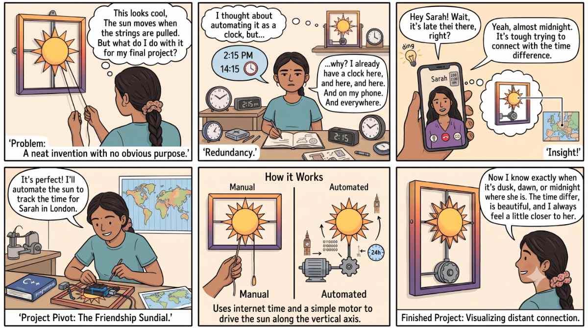
Prompt : My final project is inspired by these mechanical picture frames with an illuminated sun that can be moved along an axis. I thought about automating this, but then I questioned why I would need it as a clock when I already have clocks around me. This led to the idea of using it to show the time of a friend living abroad. If the sun could move on its own based on time, it would become a visually appealing way of displaying it. illustrate this as a comic strip with Indian woman
Ideation Process
Concept Evolution
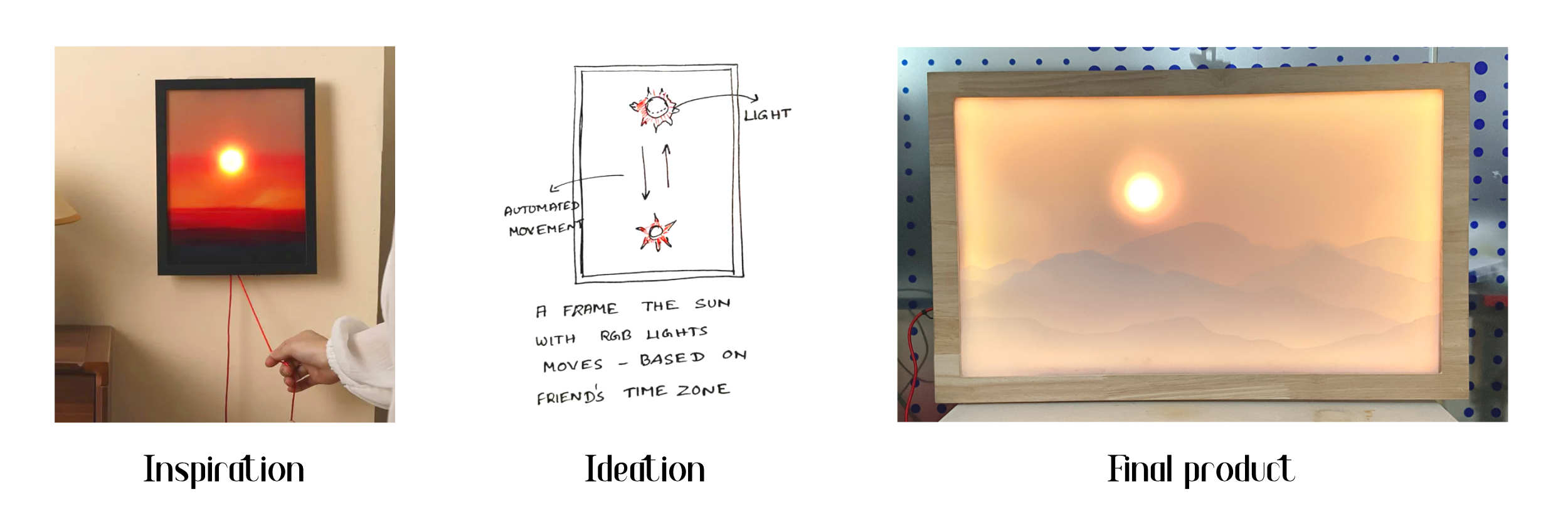
Image source on left: This was the design that inspired me to develop the Celestial Arc project. The first plan was to make it automated, then came the idea of syncing it as a dual clock. The initial sketch shows how I thought the product would look.
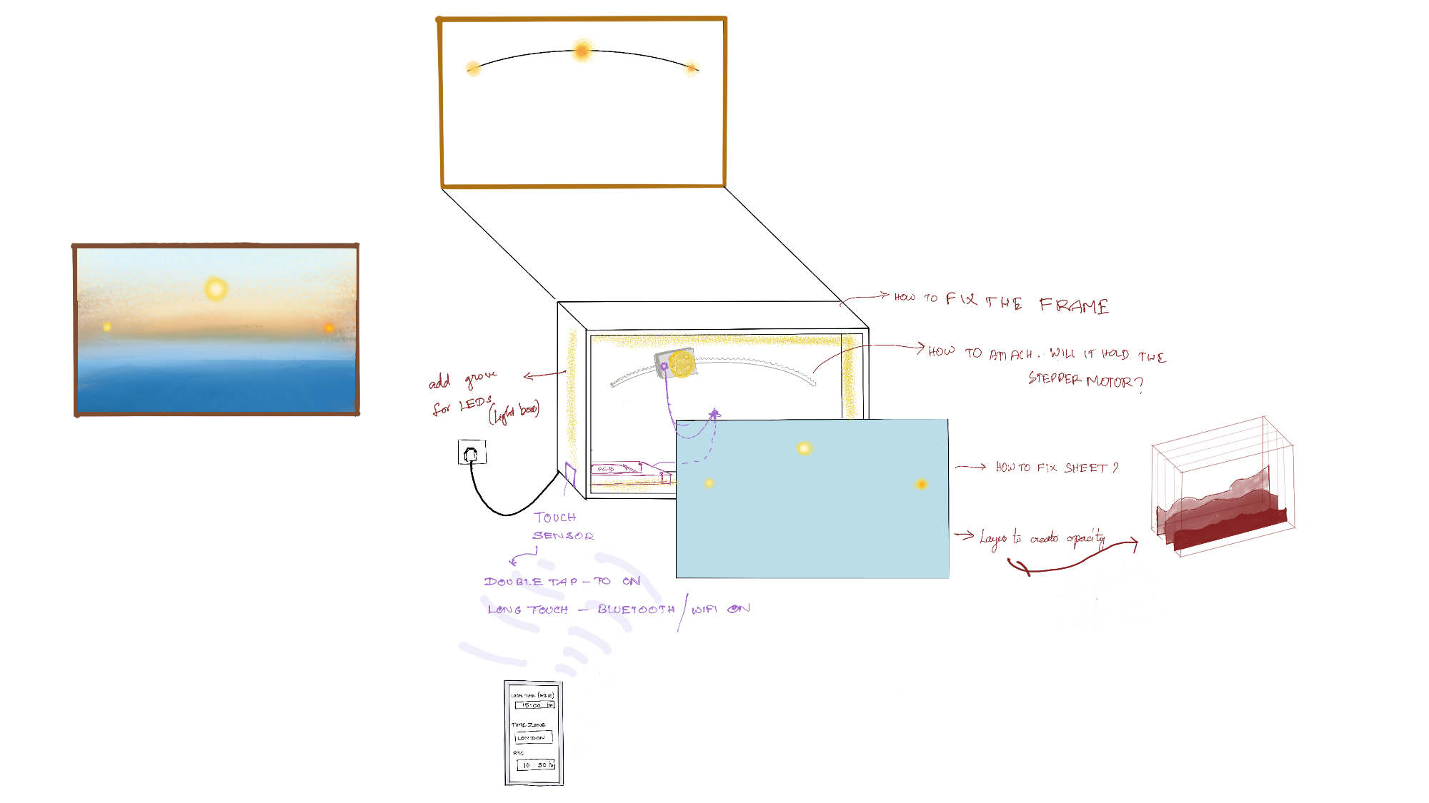
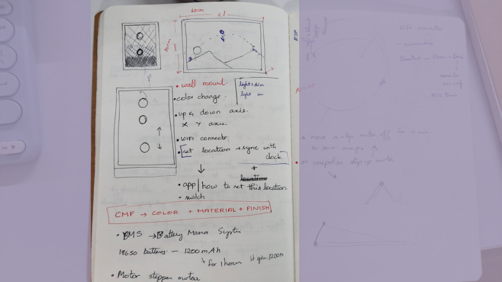
This was sketched on Procreate around Week 15. This gave a basic idea of the outlook. At the same time, it also raised questions about the fixing, wire connections, number of boards required, and how each part was going to be fixed.
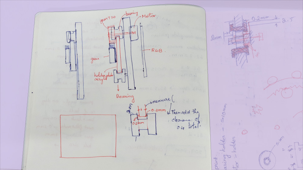
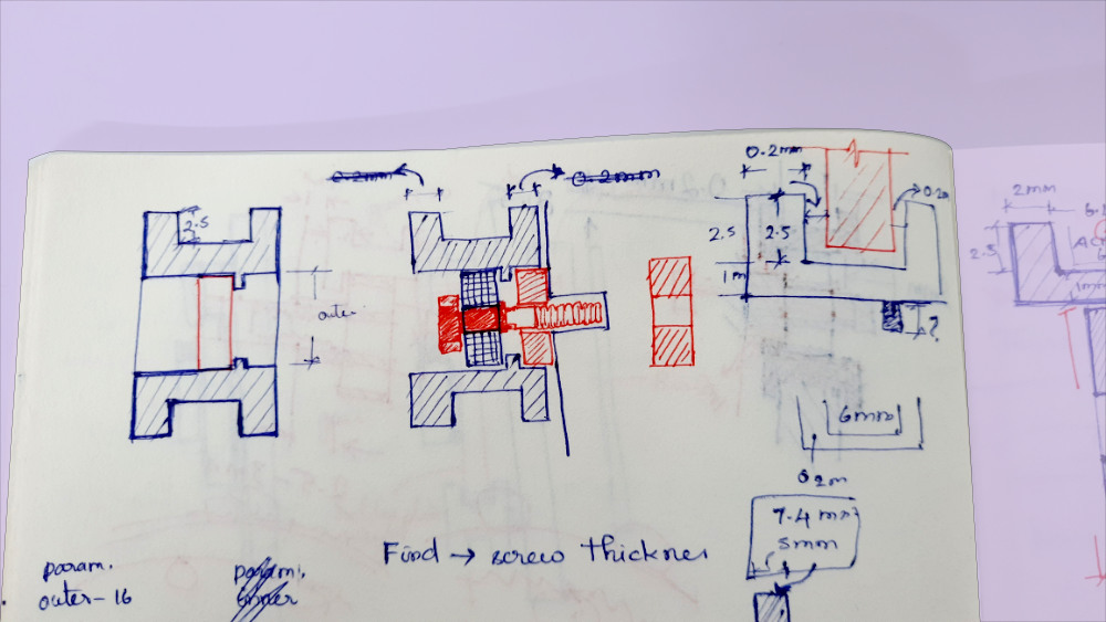
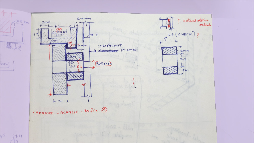
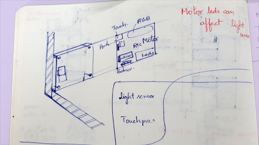
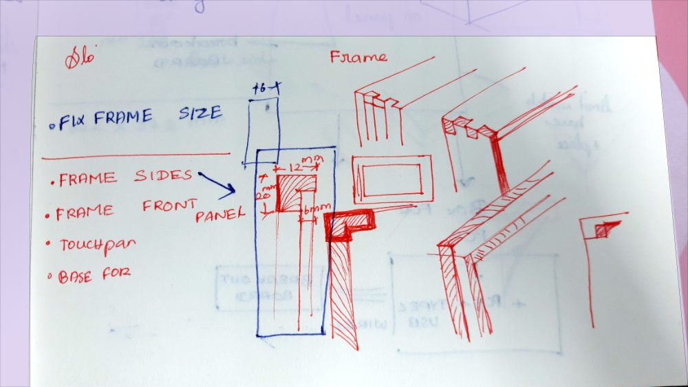
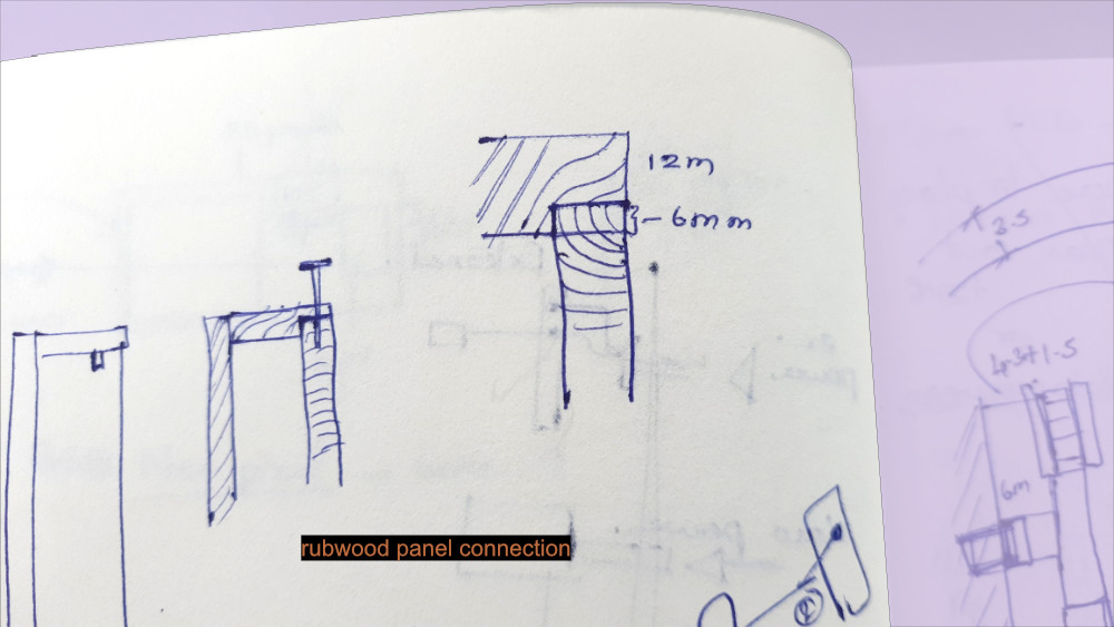
Hand Sketches
As the project moved closer to reality, the concept sketches were finalized, and it was time to focus on more technical sketches and develop a deeper understanding of its mechanical working.
3D Model in Fusion
3D model done in fusion
We learnt this software in WEEK 2 - Computer Aided Design
Design Journey
Design Journey -Post Production
Project assembly
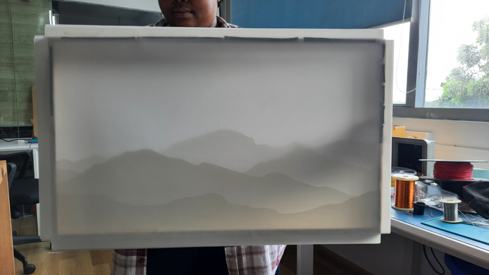
The synthetic paper stuck in layers.
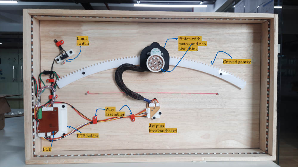
Internal and the main aspect of the design.
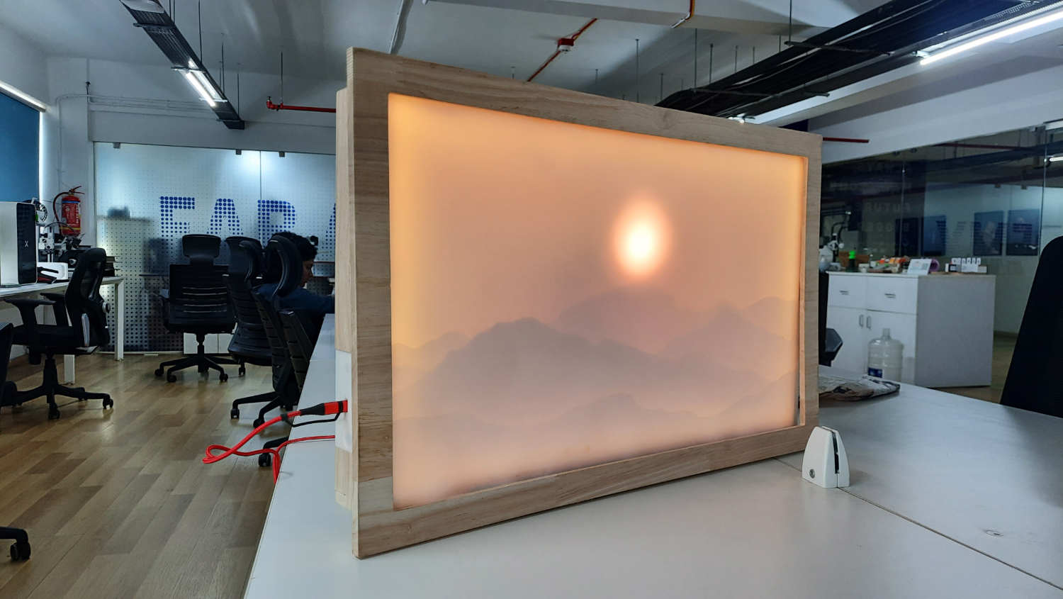
The assembled product powered by type c charger
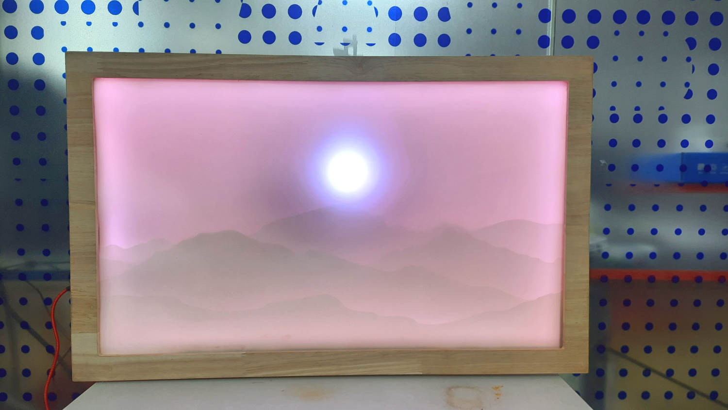
The backlight changes when it is night time.
Few details
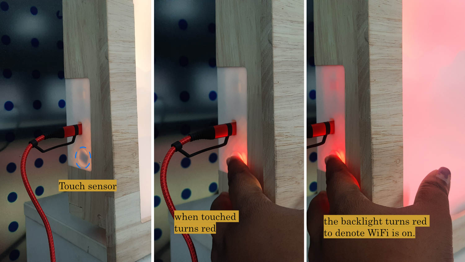
The interactive feature when tuning on Wifi to change time in the app that pops open
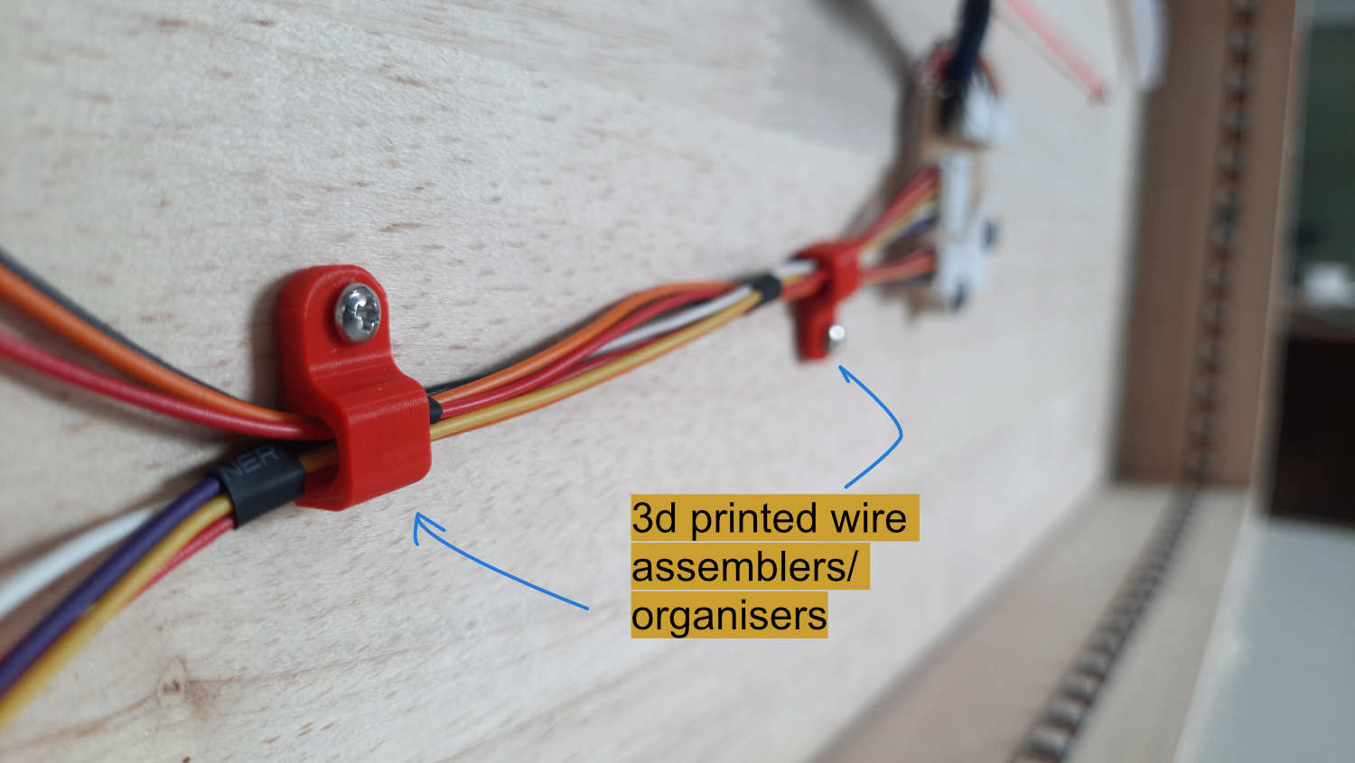
Wire management with 3d printed modules
Firmware
#include <Wire.h>
#include <RTClib.h>
#include <Adafruit_NeoPixel.h>
#include <WiFi.h>
#include <WebServer.h>
#include <DNSServer.h> // captive portal — redirects all DNS queries to our IP
#include <ESPmDNS.h> // celestialarc.local fallback
// =====================================================
// PINS
// =====================================================
#define IN1 D7
#define IN2 D8
#define IN3 D9
#define IN4 D10
#define LIMIT_SWITCH D6
#define BACKLIGHT_PIN D0
#define BACKLIGHT_COUNT 118
#define SUNMOON_PIN D1
#define SUNMOON_COUNT 9
#define SDA_PIN D4
#define SCL_PIN D5
#define TOUCH_PIN D3
// =====================================================
// 24C32 EEPROM
// Most DS3231 combo boards pull A0-A2 HIGH -> 0x57.
// If yours has A0-A2 LOW, change to 0x50.
// =====================================================
#define EEPROM_I2C_ADDR 0x57
#define EEPROM_MAGIC 0xCA
#define EEPROM_ADDR_MAGIC 0x0000 // 1 byte -- magic
#define EEPROM_ADDR_TZ 0x0001 // 2 bytes -- int16_t offset in minutes
// =====================================================
// TIMEZONES (38 real-world zones, UTC baseline)
// =====================================================
struct Timezone {
const char* label;
const char* abbr;
int16_t offset; // minutes from UTC
};
const Timezone TIMEZONES[] = {
{ "UTC-12:00", "IDLW", -720 },
{ "UTC-11:00", "NUT", -660 },
{ "UTC-10:00", "HST", -600 },
{ "UTC-09:30", "MART", -570 },
{ "UTC-09:00", "AKST", -540 },
{ "UTC-08:00", "PST", -480 },
{ "UTC-07:00", "MST", -420 },
{ "UTC-06:00", "CST", -360 },
{ "UTC-05:00", "EST", -300 },
{ "UTC-04:00", "AST", -240 },
{ "UTC-03:30", "NST", -210 },
{ "UTC-03:00", "BRT", -180 },
{ "UTC-02:00", "GST", -120 },
{ "UTC-01:00", "AZOT", -60 },
{ "UTC+00:00", "UTC", 0 },
{ "UTC+01:00", "CET", 60 },
{ "UTC+02:00", "EET", 120 },
{ "UTC+03:00", "MSK", 180 },
{ "UTC+03:30", "IRST", 210 },
{ "UTC+04:00", "GST", 240 },
{ "UTC+04:30", "AFT", 270 },
{ "UTC+05:00", "PKT", 300 },
{ "UTC+05:30", "IST", 330 },
{ "UTC+05:45", "NPT", 345 },
{ "UTC+06:00", "BST", 360 },
{ "UTC+06:30", "MMT", 390 },
{ "UTC+07:00", "ICT", 420 },
{ "UTC+08:00", "CST", 480 },
{ "UTC+08:45", "ACWST", 525 },
{ "UTC+09:00", "JST", 540 },
{ "UTC+09:30", "ACST", 570 },
{ "UTC+10:00", "AEST", 600 },
{ "UTC+10:30", "LHST", 630 },
{ "UTC+11:00", "SBT", 660 },
{ "UTC+12:00", "NZST", 720 },
{ "UTC+12:45", "CHAST", 765 },
{ "UTC+13:00", "TOT", 780 },
{ "UTC+14:00", "LINT", 840 }
};
const uint8_t TZ_COUNT = sizeof(TIMEZONES) / sizeof(TIMEZONES[0]);
int16_t activeTZOffset = 0; // loaded from EEPROM; defaults to UTC
// =====================================================
// RTC
// =====================================================
RTC_DS3231 rtc;
// =====================================================
// LEDS
// =====================================================
Adafruit_NeoPixel backlight(BACKLIGHT_COUNT, BACKLIGHT_PIN, NEO_GRB + NEO_KHZ800);
Adafruit_NeoPixel sunMoon(SUNMOON_COUNT, SUNMOON_PIN, NEO_GRB + NEO_KHZ800);
// =====================================================
// MOTOR
// =====================================================
const uint8_t stepSequence[8][4] = {
{1,0,0,0},
{1,1,0,0},
{0,1,0,0},
{0,1,1,0},
{0,0,1,0},
{0,0,1,1},
{0,0,0,1},
{1,0,0,1}
};
const unsigned long stepDelayMs = 1;
const long MAX_POSITION = 23500;
const long HOMING_MAX_STEPS = 30000;
int currentStepIndex = 0;
long currentPosition = 0;
long targetPosition = 0;
// =====================================================
// WIFI / WEBSERVER
// =====================================================
const char* AP_SSID = "CelestialArc";
WebServer server(80);
DNSServer dnsServer; // captive portal DNS
const byte DNS_PORT = 53;
bool pendingMotorTest = false; // set by /test route, consumed in loop
// =====================================================
// TIMERS
// =====================================================
unsigned long lastStepTime = 0;
int lastPrintedMinute = -1;
int lastTimeSlot = -1;
// AP timeout: exit settings if no client connects within this window
const unsigned long AP_TIMEOUT_MS = 60000UL; // 60 seconds
unsigned long apStartTime = 0;
bool apClientEverConnected = false;
// =====================================================
// TOUCH BUTTON
// =====================================================
bool lastTouchState = false;
unsigned long touchPressStart = 0;
bool longPressHandled = false;
const unsigned long LONG_PRESS_MS = 2000;
// =====================================================
// STATES
// =====================================================
enum SystemState { HOMING, STARTUP_SYNC, RUNNING, SETTINGS, FAULT };
SystemState systemState = HOMING;
// =====================================================
// 24C32 EEPROM HELPERS
// =====================================================
void eeprom_writeByte(uint16_t addr, uint8_t data) {
Wire.beginTransmission(EEPROM_I2C_ADDR);
Wire.write((uint8_t)(addr >> 8));
Wire.write((uint8_t)(addr & 0xFF));
Wire.write(data);
Wire.endTransmission();
delay(5); // 24C32 write cycle max 5ms
}
uint8_t eeprom_readByte(uint16_t addr) {
Wire.beginTransmission(EEPROM_I2C_ADDR);
Wire.write((uint8_t)(addr >> 8));
Wire.write((uint8_t)(addr & 0xFF));
Wire.endTransmission(false); // repeated start
Wire.requestFrom((uint8_t)EEPROM_I2C_ADDR, (uint8_t)1);
return Wire.available() ? Wire.read() : 0xFF;
}
void eeprom_writeInt16(uint16_t addr, int16_t value) {
eeprom_writeByte(addr, (uint8_t)((uint16_t)value >> 8));
eeprom_writeByte(addr + 1, (uint8_t)((uint16_t)value & 0xFF));
}
int16_t eeprom_readInt16(uint16_t addr) {
uint8_t hi = eeprom_readByte(addr);
uint8_t lo = eeprom_readByte(addr + 1);
return (int16_t)(((uint16_t)hi << 8) | lo);
}
void loadTimezoneFromEEPROM() {
uint8_t magic = eeprom_readByte(EEPROM_ADDR_MAGIC);
if (magic == EEPROM_MAGIC) {
int16_t stored = eeprom_readInt16(EEPROM_ADDR_TZ);
for (uint8_t i = 0; i < TZ_COUNT; i++) {
if (TIMEZONES[i].offset == stored) {
activeTZOffset = stored;
Serial.print("TZ loaded from EEPROM: ");
Serial.println(stored);
return;
}
}
Serial.println("EEPROM TZ unrecognised, defaulting UTC");
} else {
Serial.println("EEPROM uninitialised, defaulting UTC");
}
activeTZOffset = 0;
}
void saveTimezoneToEEPROM(int16_t offset) {
eeprom_writeByte(EEPROM_ADDR_MAGIC, EEPROM_MAGIC);
eeprom_writeInt16(EEPROM_ADDR_TZ, offset);
Serial.print("TZ saved: ");
Serial.println(offset);
}
// =====================================================
// TIME HELPERS
// =====================================================
DateTime applyOffset(DateTime utc, int16_t offsetMinutes) {
uint32_t unix = utc.unixtime() + (int32_t)offsetMinutes * 60L;
return DateTime(unix);
}
DateTime localNow() {
return applyOffset(rtc.now(), activeTZOffset);
}
// =====================================================
// LED FUNCTIONS
// =====================================================
void setBacklightColor(uint8_t r, uint8_t g, uint8_t b) {
for (int i = 0; i < BACKLIGHT_COUNT; i++)
backlight.setPixelColor(i, backlight.Color(r, g, b));
backlight.show();
}
void setSunMoonColor(uint8_t r, uint8_t g, uint8_t b) {
for (int i = 0; i < SUNMOON_COUNT; i++)
sunMoon.setPixelColor(i, sunMoon.Color(r, g, b));
sunMoon.show();
}
void dayMode() {
setBacklightColor(255, 180, 0);
setSunMoonColor(255, 120, 20);
}
void nightMode() {
setBacklightColor(0, 0, 0);
setSunMoonColor(180, 180, 255);
}
void settingsMode_LED() {
backlight.setBrightness(128);
setBacklightColor(255, 0, 0);
}
void restoreNormalBrightness() {
backlight.setBrightness(50);
}
// =====================================================
// MOTOR FUNCTIONS
// =====================================================
void writeMotorOutputs() {
digitalWrite(IN1, stepSequence[currentStepIndex][0]);
digitalWrite(IN2, stepSequence[currentStepIndex][1]);
digitalWrite(IN3, stepSequence[currentStepIndex][2]);
digitalWrite(IN4, stepSequence[currentStepIndex][3]);
}
void stepCW() {
currentStepIndex = (currentStepIndex + 1) % 8;
writeMotorOutputs();
currentPosition++;
}
void stepCCW() {
currentStepIndex = (currentStepIndex + 7) % 8;
writeMotorOutputs();
currentPosition--;
}
void motorOff() {
digitalWrite(IN1, LOW);
digitalWrite(IN2, LOW);
digitalWrite(IN3, LOW);
digitalWrite(IN4, LOW);
}
void fastTravelTo(long target) {
const long MAX_TRAVEL = MAX_POSITION + 500;
long steps = 0;
while (currentPosition < target && steps < MAX_TRAVEL) { stepCW(); delay(1); steps++; }
while (currentPosition > target && steps < MAX_TRAVEL) { stepCCW(); delay(1); steps++; }
motorOff();
lastStepTime = millis();
}
// =====================================================
// RTC PRINT
// =====================================================
void printTime(DateTime t) {
Serial.printf("Local: %02d:%02d\n", t.hour(), t.minute());
}
// =====================================================
// TIME SLOT
// =====================================================
int get5MinuteSlot(DateTime t) { return t.minute() / 5; }
// =====================================================
// POSITION CALCULATION
// =====================================================
long calculatePosition(DateTime local) {
int hour = local.hour();
int minute = local.minute();
int flooredMinute = (minute / 5) * 5;
if ((hour > 6 && hour < 18) || (hour == 6) || (hour == 18 && flooredMinute == 0)) {
long minutesSince6AM = ((hour - 6) * 60L) + flooredMinute;
if (minutesSince6AM > 720) minutesSince6AM = 720;
return (minutesSince6AM * MAX_POSITION) / 720L;
}
long minutesSince6PM;
if (hour >= 18) minutesSince6PM = ((hour - 18) * 60L) + flooredMinute;
else minutesSince6PM = ((hour + 6) * 60L) + flooredMinute;
long position = MAX_POSITION - ((minutesSince6PM * MAX_POSITION) / 720L);
return (position < 0) ? 0 : position;
}
// =====================================================
// LIGHTING
// =====================================================
void updateLighting(DateTime local) {
int h = local.hour(), m = local.minute();
if ((h > 6 && h < 18) || (h == 6) || (h == 18 && m == 0)) dayMode();
else nightMode();
}
// =====================================================
// HOMING
// =====================================================
long homingSteps = 0;
void runHoming() {
if (digitalRead(LIMIT_SWITCH) == LOW) {
currentPosition = 0;
motorOff();
Serial.println("HOME FOUND");
systemState = STARTUP_SYNC;
return;
}
if (homingSteps >= HOMING_MAX_STEPS) {
motorOff();
Serial.println("HOMING FAILED");
systemState = FAULT;
return;
}
if (millis() - lastStepTime >= stepDelayMs) {
lastStepTime = millis();
stepCCW();
homingSteps++;
}
}
// =====================================================
// STARTUP SYNC
// =====================================================
void startupSync() {
DateTime local = localNow();
updateLighting(local);
targetPosition = calculatePosition(local);
Serial.print("Sync -> position ");
Serial.println(targetPosition);
fastTravelTo(targetPosition);
lastTimeSlot = get5MinuteSlot(local);
Serial.println("Sync complete -> RUNNING");
systemState = RUNNING;
}
// =====================================================
// MOTOR TRACKING
// =====================================================
void updateMotor() {
if (millis() - lastStepTime < stepDelayMs) return;
lastStepTime = millis();
if (currentPosition < targetPosition) stepCW();
else if (currentPosition > targetPosition) stepCCW();
else motorOff();
}
// =====================================================
// TOUCH BUTTON
// =====================================================
void handleTouchButton() {
bool touched = (digitalRead(TOUCH_PIN) == HIGH);
if (touched && !lastTouchState) {
touchPressStart = millis();
longPressHandled = false;
}
if (touched && !longPressHandled) {
if (millis() - touchPressStart >= LONG_PRESS_MS) {
longPressHandled = true;
if (systemState == RUNNING) enterSettingsMode();
}
}
lastTouchState = touched;
}
// =====================================================
// MOTOR TEST SEQUENCE
// Called from loop() when pendingMotorTest is true.
// Blocking by design — this is a deliberate full-sweep test.
// Sequence: home → MAX_POSITION (dayMode) → home (nightMode) → RUNNING
// =====================================================
void runMotorTest() {
pendingMotorTest = false;
Serial.println("MOTOR TEST: starting");
// ---- Phase 1: Home ----
Serial.println("MOTOR TEST: homing");
long safetySteps = 0;
while (digitalRead(LIMIT_SWITCH) != LOW && safetySteps < HOMING_MAX_STEPS) {
stepCCW();
delay(1);
safetySteps++;
}
if (digitalRead(LIMIT_SWITCH) != LOW) {
// Homing failed during test — abort and go to FAULT
motorOff();
Serial.println("MOTOR TEST: homing failed — entering FAULT");
systemState = FAULT;
return;
}
currentPosition = 0;
motorOff();
Serial.println("MOTOR TEST: home found");
delay(300);
// ---- Phase 2: Sweep to MAX_POSITION in dayMode ----
Serial.println("MOTOR TEST: sweeping to MAX (dayMode)");
dayMode();
fastTravelTo(MAX_POSITION);
delay(500); // brief pause at end of arc so it's visible
// ---- Phase 3: Return to home in nightMode ----
Serial.println("MOTOR TEST: returning home (nightMode)");
nightMode();
fastTravelTo(0);
delay(300);
motorOff();
Serial.println("MOTOR TEST: complete — resuming RUNNING");
// ---- Phase 4: Exit settings and resume normally ----
exitSettingsMode(activeTZOffset); // no TZ change, just clean resume
}
// =====================================================
// SETTINGS MODE — ENTER / EXIT
// =====================================================
void enterSettingsMode() {
Serial.println("-> SETTINGS MODE");
systemState = SETTINGS;
settingsMode_LED();
WiFi.softAP(AP_SSID);
IPAddress apIP = WiFi.softAPIP(); // default: 192.168.4.1
Serial.print("AP IP: ");
Serial.println(apIP);
// Captive portal: answer every DNS query with our own IP.
// This makes Android/iOS/Windows detect a "login required" network
// and pop the browser open automatically.
dnsServer.start(DNS_PORT, "*", apIP);
setupWebServer();
server.begin();
// mDNS: reachable at http://celestialarc.local as a named fallback
if (MDNS.begin("celestialarc")) {
MDNS.addService("http", "tcp", 80);
Serial.println("mDNS: http://celestialarc.local");
}
// Start the no-connection timeout countdown
apStartTime = millis();
apClientEverConnected = false;
Serial.println("Web server started (60s timeout if no client connects)");
}
void exitSettingsMode(int16_t newOffset) {
bool tzChanged = (newOffset != activeTZOffset);
if (tzChanged) {
activeTZOffset = newOffset;
saveTimezoneToEEPROM(activeTZOffset);
Serial.print("TZ changed to: ");
Serial.println(activeTZOffset);
}
server.stop();
dnsServer.stop();
MDNS.end();
WiFi.softAPdisconnect(true);
WiFi.mode(WIFI_OFF);
restoreNormalBrightness();
DateTime local = localNow();
updateLighting(local);
if (tzChanged) {
long newTarget = calculatePosition(local);
Serial.print("Fast-travel -> ");
Serial.println(newTarget);
fastTravelTo(newTarget);
targetPosition = newTarget;
}
lastTimeSlot = get5MinuteSlot(local);
lastStepTime = millis();
systemState = RUNNING;
Serial.println("-> RUNNING");
}
// =====================================================
// WEBPAGE HELPERS
// =====================================================
uint8_t tzIndexByOffset(int16_t offset) {
for (uint8_t i = 0; i < TZ_COUNT; i++)
if (TIMEZONES[i].offset == offset) return i;
return 14; // UTC fallback
}
String formatHMS(DateTime t) {
char buf[9];
snprintf(buf, sizeof(buf), "%02d:%02d:%02d", t.hour(), t.minute(), t.second());
return String(buf);
}
String formatDate(DateTime t) {
const char* days[] = {"Sunday","Monday","Tuesday","Wednesday",
"Thursday","Friday","Saturday"};
const char* months[] = {"January","February","March","April","May","June",
"July","August","September","October","November","December"};
return String(days[t.dayOfTheWeek()]) + ", " +
String(t.day()) + " " +
String(months[t.month() - 1]) + " " +
String(t.year());
}
// =====================================================
// WEBPAGE BUILD
// =====================================================
String buildHTMLPage() {
DateTime utcTime = rtc.now();
DateTime locTime = applyOffset(utcTime, activeTZOffset);
uint8_t activeIdx = tzIndexByOffset(activeTZOffset);
// Build timezone <option> list
String tzOptions = "";
for (uint8_t i = 0; i < TZ_COUNT; i++) {
tzOptions += "<option value=\"";
tzOptions += TIMEZONES[i].offset;
tzOptions += "\"";
if (i == activeIdx) tzOptions += " selected";
tzOptions += ">";
tzOptions += TIMEZONES[i].label;
tzOptions += " \xe2\x80\x94 "; // em dash UTF-8
tzOptions += TIMEZONES[i].abbr;
tzOptions += "</option>\n";
}
// Build JS timezone array (mirrors C++ array for client-side time math)
String jsTZArray = "[\n";
for (uint8_t i = 0; i < TZ_COUNT; i++) {
jsTZArray += "{offset:";
jsTZArray += TIMEZONES[i].offset;
jsTZArray += ",abbr:\"";
jsTZArray += TIMEZONES[i].abbr;
jsTZArray += "\",label:\"";
jsTZArray += TIMEZONES[i].label;
jsTZArray += "\"}";
if (i < TZ_COUNT - 1) jsTZArray += ",";
jsTZArray += "\n";
}
jsTZArray += "]";
String html = "";
html.reserve(8000);
html += "<!DOCTYPE html><html lang='en'><head>"
"<meta charset='UTF-8'>"
"<meta name='viewport' content='width=device-width,initial-scale=1.0'>"
"<title>CelestialArc Settings</title>"
"<style>"
"*{box-sizing:border-box;margin:0;padding:0}"
"body{font-family:-apple-system,BlinkMacSystemFont,'Segoe UI',sans-serif;"
"background:#0f0f1a;color:#e0d8ff;min-height:100vh;"
"display:flex;flex-direction:column;align-items:center;"
"justify-content:center;padding:24px;gap:14px;}"
"h1{font-size:1.25rem;font-weight:500;letter-spacing:.12em;"
"color:#a090d0;text-transform:uppercase;}"
".card{background:#1a1830;border:1px solid #2e2a50;border-radius:16px;"
"padding:24px 28px;width:100%;max-width:400px;}"
".lbl{font-size:.65rem;text-transform:uppercase;letter-spacing:.15em;"
"color:#5a5080;margin-bottom:8px;}"
".time-row{display:flex;align-items:baseline;gap:10px;}"
".t-big{font-size:2.8rem;font-weight:300;letter-spacing:.04em;"
"color:#fff;font-variant-numeric:tabular-nums;}"
".t-abbr{font-size:.85rem;color:#7060a0;}"
".date-ln{font-size:.88rem;color:#7060a0;margin-top:4px;margin-bottom:16px;}"
".divider{border:none;border-top:1px solid #2e2a50;margin:14px 0;}"
".utc-row{display:flex;align-items:center;justify-content:space-between;}"
".utc-lbl{font-size:.65rem;text-transform:uppercase;letter-spacing:.12em;color:#5a5080;}"
".utc-t{font-size:1.3rem;font-weight:300;letter-spacing:.04em;"
"color:#5a5080;font-variant-numeric:tabular-nums;}"
"select{width:100%;background:#0f0f1a;color:#e0d8ff;"
"border:1px solid #2e2a50;border-radius:10px;padding:11px 36px 11px 14px;"
"font-size:.88rem;appearance:none;cursor:pointer;"
"background-image:url(\"data:image/svg+xml,%3Csvg xmlns='http://www.w3.org/2000/svg'"
" width='12' height='12' viewBox='0 0 24 24' fill='none' stroke='%237060a0'"
" stroke-width='2'%3E%3Cpath d='M6 9l6 6 6-6'/%3E%3C/svg%3E\");"
"background-repeat:no-repeat;background-position:right 14px center;}"
"select:focus{outline:none;border-color:#534AB7;}"
".preview-row{display:flex;align-items:baseline;gap:8px;margin-top:12px;min-height:30px;}"
".prev-t{font-size:1.6rem;font-weight:300;color:#c0b0ff;font-variant-numeric:tabular-nums;}"
".prev-lbl{font-size:.8rem;color:#5a5080;}"
".save-btn{background:#534AB7;color:#fff;border:none;border-radius:10px;"
"padding:14px;font-size:.95rem;font-weight:500;cursor:pointer;"
"width:100%;max-width:400px;transition:background .2s;}"
".save-btn:hover{background:#7F77DD;}"
".test-btn{background:#1a3a2a;color:#4dbb7a;border:1px solid #2a5a3a;"
"border-radius:10px;padding:13px;font-size:.9rem;font-weight:500;"
"cursor:pointer;width:100%;max-width:400px;transition:background .2s;}"
".test-btn:hover{background:#1e4a32;}"
".test-note{font-size:.68rem;color:#3a3060;text-align:center;"
"max-width:400px;line-height:1.5;}"
"</style></head><body>"
"<h1>☄ CelestialArc</h1>";
// --- Active timezone card ---
html += "<div class='card'>"
"<div class='lbl'>Active timezone — ";
html += TIMEZONES[activeIdx].label;
html += " (";
html += TIMEZONES[activeIdx].abbr;
html += ")</div>"
"<div class='time-row'>"
"<span class='t-big' id='localClock'>";
html += formatHMS(locTime);
html += "</span>"
"<span class='t-abbr' id='localAbbr'>";
html += TIMEZONES[activeIdx].abbr;
html += "</span></div>"
"<div class='date-ln' id='localDate'>";
html += formatDate(locTime);
html += "</div>"
"<hr class='divider'>"
"<div class='utc-row'>"
"<span class='utc-lbl'>UTC</span>"
"<span class='utc-t' id='utcClock'>";
html += formatHMS(utcTime);
html += "</span></div></div>";
// --- Timezone selector card ---
html += "<div class='card'>"
"<div class='lbl'>Select timezone</div>"
"<select id='tzSelect' onchange='onTZChange(this)'>\n";
html += tzOptions;
html += "</select>"
"<div class='preview-row'>"
"<span class='prev-t' id='previewClock'></span>"
"<span class='prev-lbl' id='previewLabel'></span>"
"</div></div>";
// --- Save form ---
html += "<form action='/save' method='POST'>"
"<input type='hidden' name='tz' id='tzHidden' value='";
html += activeTZOffset;
html += "'>"
"<button class='save-btn' type='submit'>Save & Exit</button>"
"</form>";
// --- Motor test button ---
html += "<form action='/test' method='POST'>"
"<button class='test-btn' type='submit'>"
"▶ Run Motor Test"
"</button>"
"</form>"
"<div class='test-note'>"
"Homes → sweeps to MAX (day) → returns home (night) → resumes"
"</div>";
// --- Script ---
html += "<script>"
"const TZ=";
html += jsTZArray;
html += ";\n"
"const utcParts=document.getElementById('utcClock').textContent.split(':');\n"
"let uh=+utcParts[0],um=+utcParts[1],us=+utcParts[2];\n"
"let activeTZMin=";
html += activeTZOffset;
html += ";\n"
"let selectedTZMin=activeTZMin;\n"
"function pad(n){return String(n).padStart(2,'0');}\n"
"function localFromUTC(uh,um,us,offMin){\n"
" let t=uh*3600+um*60+us+offMin*60;\n"
" t=((t%86400)+86400)%86400;\n"
" return{h:Math.floor(t/3600),m:Math.floor((t%3600)/60),s:t%60};\n"
"}\n"
"function tick(){\n"
" us++;if(us>=60){us=0;um++;}if(um>=60){um=0;uh++;}if(uh>=24)uh=0;\n"
" document.getElementById('utcClock').textContent=pad(uh)+':'+pad(um)+':'+pad(us);\n"
" const loc=localFromUTC(uh,um,us,activeTZMin);\n"
" document.getElementById('localClock').textContent=pad(loc.h)+':'+pad(loc.m)+':'+pad(loc.s);\n"
" if(selectedTZMin!==activeTZMin){\n"
" const p=localFromUTC(uh,um,us,selectedTZMin);\n"
" document.getElementById('previewClock').textContent=pad(p.h)+':'+pad(p.m)+':'+pad(p.s);\n"
" }\n"
"}\n"
"setInterval(tick,1000);\n"
"function onTZChange(sel){\n"
" selectedTZMin=parseInt(sel.value);\n"
" document.getElementById('tzHidden').value=selectedTZMin;\n"
" const tz=TZ.find(t=>t.offset===selectedTZMin);\n"
" if(selectedTZMin===activeTZMin){\n"
" document.getElementById('previewClock').textContent='';\n"
" document.getElementById('previewLabel').textContent='';\n"
" } else {\n"
" const p=localFromUTC(uh,um,us,selectedTZMin);\n"
" document.getElementById('previewClock').textContent=pad(p.h)+':'+pad(p.m)+':'+pad(p.s);\n"
" document.getElementById('previewLabel').textContent=tz?tz.abbr+' '+tz.label:'';\n"
" }\n"
"}\n"
"</script></body></html>";
return html;
}
// =====================================================
// WEB SERVER ROUTES
// =====================================================
void setupWebServer() {
// ---- Captive portal detection endpoints ----
// Each OS probes a known URL; if it doesn't get the expected response
// it concludes there's a captive portal and pops the browser.
// We redirect all of them to our main page.
// iOS / macOS
server.on("/hotspot-detect.html", HTTP_GET, []() { server.sendHeader("Location", "/", true); server.send(302, "text/plain", ""); });
server.on("/library/test/success.html", HTTP_GET, []() { server.sendHeader("Location", "/", true); server.send(302, "text/plain", ""); });
// Android
server.on("/generate_204", HTTP_GET, []() { server.sendHeader("Location", "/", true); server.send(302, "text/plain", ""); });
server.on("/gen_204", HTTP_GET, []() { server.sendHeader("Location", "/", true); server.send(302, "text/plain", ""); });
// Windows (NCSI)
server.on("/ncsi.txt", HTTP_GET, []() { server.sendHeader("Location", "/", true); server.send(302, "text/plain", ""); });
server.on("/connecttest.txt", HTTP_GET, []() { server.sendHeader("Location", "/", true); server.send(302, "text/plain", ""); });
server.on("/redirect", HTTP_GET, []() { server.sendHeader("Location", "/", true); server.send(302, "text/plain", ""); });
// Catch-all: anything not matched above also redirects to main page.
// This is the safety net that makes the captive portal fully robust —
// any unknown probe URL from any OS still lands on the settings page.
server.onNotFound([]() {
server.sendHeader("Location", "/", true);
server.send(302, "text/plain", "");
});
// ---- Main routes ----
server.on("/", HTTP_GET, []() {
server.send(200, "text/html", buildHTMLPage());
});
server.on("/save", HTTP_POST, []() {
int16_t newOffset = activeTZOffset;
if (server.hasArg("tz")) {
long val = server.arg("tz").toInt();
for (uint8_t i = 0; i < TZ_COUNT; i++) {
if (TIMEZONES[i].offset == (int16_t)val) {
newOffset = (int16_t)val;
break;
}
}
}
uint8_t idx = tzIndexByOffset(newOffset);
String resp = "<!DOCTYPE html><html lang='en'><head>"
"<meta charset='UTF-8'>"
"<meta name='viewport' content='width=device-width,initial-scale=1.0'>"
"<title>CelestialArc</title>"
"<style>"
"body{font-family:-apple-system,BlinkMacSystemFont,'Segoe UI',sans-serif;"
"background:#0f0f1a;color:#e0d8ff;min-height:100vh;display:flex;"
"flex-direction:column;align-items:center;justify-content:center;"
"padding:24px;text-align:center;gap:12px;}"
"h2{font-weight:400;color:#a090d0;font-size:1.2rem;}"
"p{color:#5a5080;font-size:.85rem;line-height:1.6;}"
".tz{color:#c0b0ff;font-size:1rem;}"
"</style></head><body>"
"<h2>✓ Settings saved</h2>"
"<p class='tz'>";
resp += TIMEZONES[idx].label;
resp += " — ";
resp += TIMEZONES[idx].abbr;
resp += "</p><p>CelestialArc is syncing to the new timezone<br>"
"and resuming normal operation.</p>"
"<p>You can close this page.</p>"
"</body></html>";
server.send(200, "text/html", resp);
exitSettingsMode(newOffset);
});
server.on("/test", HTTP_POST, []() {
// Send the response immediately — the test sequence is blocking
// so we can't run it inside the handler. Set a flag and let loop() do it.
String resp = "<!DOCTYPE html><html lang='en'><head>"
"<meta charset='UTF-8'>"
"<meta name='viewport' content='width=device-width,initial-scale=1.0'>"
"<title>CelestialArc</title>"
"<style>"
"body{font-family:-apple-system,BlinkMacSystemFont,'Segoe UI',sans-serif;"
"background:#0f0f1a;color:#e0d8ff;min-height:100vh;display:flex;"
"flex-direction:column;align-items:center;justify-content:center;"
"padding:24px;text-align:center;gap:14px;}"
"h2{font-weight:400;color:#a090d0;font-size:1.2rem;}"
"p{color:#5a5080;font-size:.85rem;line-height:1.6;}"
".steps{background:#1a1830;border:1px solid #2e2a50;border-radius:12px;"
"padding:20px 24px;text-align:left;max-width:320px;width:100%;}"
".step{display:flex;align-items:center;gap:10px;padding:6px 0;"
"font-size:.85rem;color:#8070b0;border-bottom:1px solid #1e1c30;}"
".step:last-child{border-bottom:none;}"
".dot{width:8px;height:8px;border-radius:50%;background:#534AB7;flex-shrink:0;}"
"</style></head><body>"
"<h2>▶ Motor Test Running</h2>"
"<div class='steps'>"
"<div class='step'><span class='dot'></span>Homing to position 0</div>"
"<div class='step'><span class='dot'></span>Sweeping to MAX in day mode</div>"
"<div class='step'><span class='dot'></span>Returning home in night mode</div>"
"<div class='step'><span class='dot'></span>Resuming normal operation</div>"
"</div>"
"<p>CelestialArc will resume automatically.<br>You can close this page.</p>"
"</body></html>";
server.send(200, "text/html", resp);
pendingMotorTest = true; // handled in loop() after response is sent
});
}
// =====================================================
// SETUP
// =====================================================
void setup() {
Serial.begin(115200);
pinMode(IN1, OUTPUT);
pinMode(IN2, OUTPUT);
pinMode(IN3, OUTPUT);
pinMode(IN4, OUTPUT);
pinMode(LIMIT_SWITCH, INPUT_PULLUP);
pinMode(TOUCH_PIN, INPUT);
Wire.begin(SDA_PIN, SCL_PIN);
if (!rtc.begin()) {
Serial.println("RTC NOT FOUND");
backlight.begin();
backlight.setBrightness(50);
setBacklightColor(255, 0, 0);
motorOff();
systemState = FAULT;
return;
}
if (rtc.lostPower())
Serial.println("WARNING: RTC lost power - time may be invalid");
loadTimezoneFromEEPROM();
backlight.begin();
backlight.setBrightness(50);
backlight.show();
sunMoon.begin();
sunMoon.setBrightness(204);
sunMoon.show();
dayMode();
WiFi.mode(WIFI_OFF);
Serial.println("STARTING HOMING");
}
// =====================================================
// LOOP
// =====================================================
void loop() {
if (systemState == RUNNING || systemState == SETTINGS)
handleTouchButton();
switch (systemState) {
case HOMING:
runHoming();
break;
case STARTUP_SYNC:
startupSync();
break;
case RUNNING: {
DateTime local = localNow();
updateLighting(local);
if (local.minute() != lastPrintedMinute) {
lastPrintedMinute = local.minute();
printTime(local);
}
int slot = get5MinuteSlot(local);
if (slot != lastTimeSlot) {
lastTimeSlot = slot;
targetPosition = calculatePosition(local);
Serial.print("TARGET=");
Serial.println(targetPosition);
}
updateMotor();
break;
}
case SETTINGS:
dnsServer.processNextRequest(); // must be called every loop for captive portal
updateMotor();
server.handleClient();
// Motor test requested via webpage — run after HTTP response is flushed
if (pendingMotorTest) {
runMotorTest(); // blocking; exits settings mode internally when done
break;
}
// Latch once any device joins the AP — timer stops permanently
if (!apClientEverConnected && WiFi.softAPgetStationNum() > 0) {
apClientEverConnected = true;
Serial.println("Client connected — AP timeout cancelled");
}
// If no client ever connected and the window has expired, bail out
if (!apClientEverConnected &&
(millis() - apStartTime >= AP_TIMEOUT_MS)) {
Serial.println("AP timeout — no client connected, returning to RUNNING");
exitSettingsMode(activeTZOffset); // no TZ change, just clean exit
}
break;
case FAULT:
motorOff();
break;
}
}
Moving to position
Bill of Materials
| Sl. No. | Category | Item | Quantity | Unit Cost (₹) | Total Cost (₹) | Supplier | Alternate Supplier | Search Name |
|---|---|---|---|---|---|---|---|---|
| Electronics | ||||||||
| 1 | Microcontroller | XIAO ESP32-C6 | 1 | 555 | 555 | FAB INVENTORY | Robu | Seeed Studio XIAO ESP32C6 |
| 2 | Stepper Motor | 28BYJ-48 Stepper Motor 5V | 1 | 92 | 92 | FAB INVENTORY | Robu | 28BYJ-48 Stepper Motor DC 5V |
| 3 | Motor Driver | ULN2003A IC | 1 | 75 | 75 | ROBU | Robu | ULN2003LVDR Texas Instruments Darlington Transistor Array |
| 4 | NeoPixel | WS2812B RGB SMD 5050 LED | 9 | 5 | 45 | FAB INVENTORY | Ktron | WS2812B RGB SMD 5050 LED |
| 6 | RTC | DS3231 RTC Module | 1 | 158 | 158 | ROBU | Robokits | DS3231 AT24C32 High Precision Clock I2C Module |
| 7 | Limit Switch | Limit Switch | 1 | 49 | 49 | FAB INVENTORY | Robu | OMRON 3D Printer Limit Switch ENDSTOP SS-5GL |
| 8 | Light Sensor | CJMCU TEMT6000 Ambient Light Sensor Module | 1 | 80 | 80 | ROBU | Robu | CJMCU TEMT6000 Ambient Light Sensor Module |
| 9 | Battery for RTC | CR2032 Coin Cell Battery | 1 | 43 | 43 | ROBU | Robu | Panasonic CR2032 3V Lithium Coin Battery |
| 10 | NeoPixel Strip | WS2812B Addressable LED Strip | 1 | 720 | 720 | Quartz Components | Quartz Components | WS2812B Neopixel LED Strip 60 LED/Meter |
| Mechanical | ||||||||
| 1 | Bearings | Transparent OpenBuilds 5mm V-Shaped Pulley | 3 | 64 | 192 | Flyrobo | Flyrobo | Transparent OpenBuilds 5mm V-Shaped Pulley |
| 2 | Rubwood | 18mm Rubwood Sheet (8x4 ft) | 12 | 135 | 1620 | FAB INVENTORY | IndiaMART | 18mm Rubwood |
| 3 | Acrylic Sheet | 6mm Acrylic Sheet | 2.5 | 110 | 275 | FAB INVENTORY | IndiaMART | Acrylic Sheet |
| 4 | Synthetic Paper | Synthetic Paper | 2 | 50 | 100 | Local Store | Phoenix Kochi | Synthetic Paper |
Total electronics cost: ₹1,817.
Total mechanical cost: ₹2,187.
Total project cost: ₹4,004.
Licence

Anyone may use and adapt this design for non commercial purposes with proper credit. Any derivative work must be shared under the same Creative Commons license. Since this project was inspired by the work of others, I hope sharing it openly will help others learn, build upon it, and create new ideas.
Design files - download
Acknowledgement
Instructors : Sibin KS Jogin Francis Revishankar S Saheen Palayi Mufeed Mohamed Namita Aravind Akhil G Babu Akash Edamana Sreyas George
Global Instructors : Pradnya P Shindekar Rico Kanthatham Ye Eun Miriam Choi Adrian Torres
Batchmates : Abhishek Shah Ali Abdul Gafoor Archita B K Ashtami P S Kevin Jijo Merin Cyriac Mishael Sharaf Nadec Biju Kurian