WEEK 18
Applications and Implications, Project Development
How the week started
This is ongoing along with the final project execution. Still also a time to realsie and analyse how much my project has evolved or cut short.
How the week ended
This week's documentation was doen in a day. A pretty long exhausting day I would say.
Week 18’s Assignment
Applications and Implications:
- 2D and 3D design
- Additive and subtractive fabrication processes
- Electronics design and production
- Embedded microcontroller interfacing and programming
- System integration and packaging.
- Where possible, you should make rather than buy the parts of your project.
- Projects can be separate or joint, but need to show individual mastery of the skills, and be independently operable.
- Prepare drafts of your final project summary slide (presentation.png, 1920×1080).
- Prepare a video clip (presentation.mp4, 1080p HTML5, approximately 1 minute, less than 25 MB).
- Place both files in your root directory.
- Check that they are linked in the final presentation schedule.
Plan a final project masterpiece that integrates the range of units covered.
Your project should incorporate:
Project Assignment
Final Project Requirements
See Final Project Requirements for a complete list of requirements you must fulfil.
Document a final project masterpiece that integrates the range of units covered, answering:
- What does it do?
- Who's done what beforehand?
- What did you design?
- What sources did you use?
- What materials and components were used?
- Where did they come from?
- How much did they cost?
- What parts and systems were made?
- What processes were used?
- What questions were answered?
- What worked? What didn't?
- How was it evaluated?
- What are the implications?
Prepare a summary slide and a one minute video showing its conception, construction, and operation. Your project should incorporate 2D and 3D design, additive and subtractive fabrication processes, electronics design and production, embedded microcontroller interfacing and programming, system integration and packaging. Where possible, you should make rather than buy the parts of your project. Projects can be separate or joint, but need to show individual mastery of the skills, and be independently operable. Present your final project.
A brief introduction
Celestial Arc is a kinetic dual time zone clock that transforms timekeeping into an artistic experience. It is both a functional timepiece and a wall décor piece. Celestial Arc allows users to keep track of the time of a friend or loved one living in another part of the world. During the day, the glowing ring acts as the sun, gradually travelling along an arc to represent the passage of time. At night, it transitions into the moon, creating a dynamic and calming visual display.
Assignment
What will it do?
In simple terms, Celestial Arc is an artistic clock that combines motion of sun, light, and minimalist scenery to create a unique way of experiencing time. Designed to display the time of a person of your choice living in another country, it serves as both a functional timepiece and a decorative wall feature. Rather than relying on traditional clock hands, it subtly represents the passage of time through movement and light, making it as much a piece of art as it is a clock.
Who's done what beforehand?
Well I am inspired from an already exisitng product. The light in that has to be manually moved
video source
I have seen similar videos of this on Pinterest. They move the sun manually, my first thought was to automate this. Then I was wondering why to see sun move when I already know the time of my place. That is when I thought of the dual clock I use to check my friend's time who is in Dubai. Thus born this idea of moving the sun based on the location of another person. Now I can have a device which passively tells me time at my friend's location
What will you design?
I am designing a kinetic clock + wall decor. The product has an intergration of Mechanical, Electrcial and Software Systems.
Mechanical system
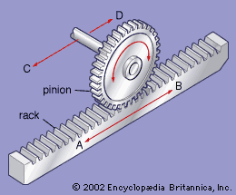
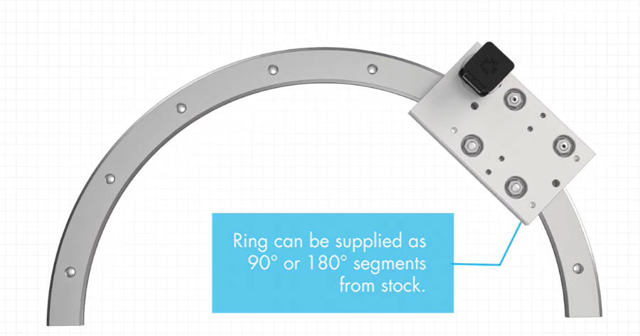
I am using a curved gantry to move the sun in the path of an arc. The gears will be designed on Fusion. The 28byj-48 stepper motor is mounted on the pinion. The curved grantry would either be 3D printed or lazer cut on acrylic sheet.
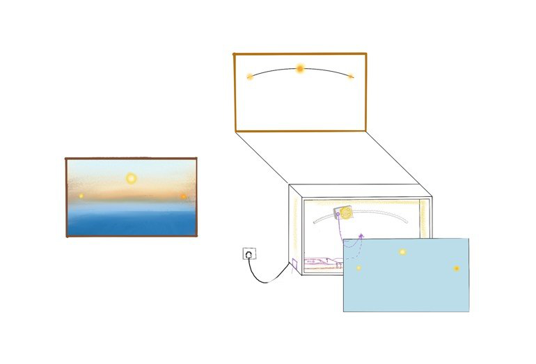
Created on procreate
The frame is to be made using rubwood, cut on Shopbot or Zund machine. The images are created by stacking synthetic paper. The paper will be lazer cut to create the lightbox frame.
The pinion will be 3d Printed
Electronic System
Milling of pcb on Modela, soldering and testing the baord. The following components are used Microcontroller -xiao esp32c6 connected to rtc, stepper motor, photo-transsitor, neo pixel ring, limit switch, capacitative touch.
Final RTC output from WEEK 9
Firmware
- Use of Ardunio to program xiao.
Software system - application
.jpg)
I created an interface for the user to change the location , based on which the time will change to that timezone.
What sources will you use?
The pretty basic source to do anything would be to Google Search. Pinterest - without which my project would'nt exist. I do need the help from instructors of Super Fab Lab Kochi.
mechanical - gear design - Gear Generator
pcb design - Input week & Output week
Neo-pixel ring PCB - Custom NeoPixel Rings From Scratch!-By- Hyper Ion Namitha Aravind
Programming and system integration - ChatGPT, Claude ,Gemini
I would also be discussing doubts with the AI mentioned above.
What materials and components will be used? Where will come from? How much will they cost?
| Sl.no | Category | Item | Quantity | Unit Cost (₹) | Total Cost | Supplier | Alternate Supplier | Search Name |
|---|---|---|---|---|---|---|---|---|
| Electronics | ||||||||
| 1 | Microcontroller | XIAO ESP32-C6 | 1 | 555 | 555 | FAB INVENTORY | Link | Seeed Studio XIAO ESP32C6 |
| 2 | Stepper motor | 28BYJ-48 Stepper Motor 5V | 1 | 92 | 92 | FAB INVENTORY | Link | 28BYJ-48 Stepper Motor DC 5V |
| 3 | Motor driver | ULN2003A IC | 1 | 75 | 75 | ROBU | Link | ULN2003LVDR Texas Instruments Darlington Array |
| 4 | Neo Pixel | WS2812B RGB SMD 5050 LED | 9 | 5 | 45 | FAB INVENTORY | Link | WS2812B RGB SMD 5050 LED |
| 6 | RTC | DS3231 RTC Module | 1 | 158 | 158 | ROBU | Link | DS3231 AT24C32 High Precision Clock Module |
| 7 | Limit switch | Limit switch | 1 | 49 | 49 | FAB INVENTORY | Link | OMRON 3D Printer Limit Switch ENDSTOP SS-5GL |
| 8 | Light sensor | CJMCU TEMT6000 Ambient Light Sensor Module | 1 | 80 | 80 | ROBU | Link | CJMCU TEMT6000 Ambient Light Sensor Module |
| 12 | Battery for RTC | CR2032 Coin Cell Battery | 1 | 43 | 43 | ROBU | Link | Panasonic CR2032 3V Lithium Coin Battery |
| 13 | Type C | Type C PD Sink Decoy | 1 | 249 | 249 | FAB INVENTORY | Link | USB C PD Trigger Decoy Module |
| TOTAL | 1097 | |||||||
| Mechanical | ||||||||
| 1 | Bearings | Transparent OpenBuilds 5mm V Shaped Pulley | 3 | 64 | 192 | Flyrobo | Link | Transparent OpenBuilds 5mm V Shaped Pulley for 3D Printer |
| 2 | Rubwood 8x4ft | 18mm Rubwood | 12 | 135 | 1620 | FAB INVENTORY | Link | 18mm Rubwood |
| 3 | Acrylic sheet | 6mm Acrylic Sheet | 2.5 | 110 | 275 | FAB INVENTORY | Link | Acrylic Sheet |
| MECHANICAL TOTAL | 2087 | |||||||
| GRAND TOTAL | 3184 | |||||||
What parts and systems were made?
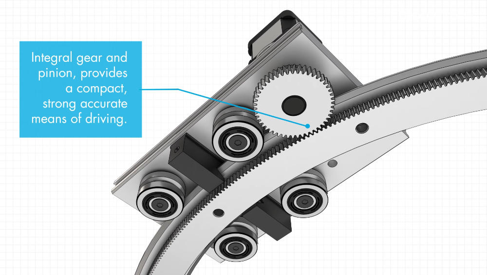
I have to create a curved gantry and pinion. The curved gantry would be cut from 6mm acrylic. We had cut an acrylic gear for our WEEK-12 Machine Week. The smaller gear would be 3D printed so it can be iterated easily if needed. The pinion would be 3D printed too.
The Frame would be made from Rubwood. It has an aesthetic appeal to it. Though not as strong as plywood, it could hold the frame and the gantry inside.
An illustrated image would be created by layering translucent material, synthetic material. This would create an aesthetic appeal.
The sun would be made using a NEOPIXEL ring. Instead of the 8 Bit WS2812 5050 RGB LED Circular Development Board, the Neopixel ring is to be custom designed, milled, and soldered.
Regarding the illumination of the sun by the Neopixel ring, the question of how to illuminate it without casting shadows arises. The synthetic paper itself seems to diffuse the light.
The PCB and breakout board would be designed, milled, and soldered, as done in previous weeks.
What processes will be used?
| METHOD | PARTS | MATERIAL | PROCESS | MACHINE | Links |
|---|---|---|---|---|---|
| Subtractive process | Frame | Rubwood | Routing | Shopbot or Zund machine | Link |
| Subtractive process | Front panel | Synthetic sheet | Laser cutting | Speedy Trotec 100 | Link |
| Subtractive process | Curved gantry | Acrylic sheet | Laser cutting | Speedy Trotec 100 | Link |
| Subtractive process | PCB | Copper clad | Milling | Modela MDX-20 3D Milling Machine | Link |
| Additive process | Gear | PLA | 3D printing | Bambu Lab A1 | Link |
| Additive process | Bearing holder | PLA | 3D printing | Bambu Lab A1 | Link |
| Digital process | Whole model | - | Digital sketch | Procreate | Link |
| Digital process | Whole model | - | 3D model | Autodesk Fusion | Link |
| Digital process | Image | - | Illustration / Trace bitmap | Affinity | Link |
What questions need to be answered?
What would be the gear ratio?
How can the pinion be prevented from sliding off the curved gantry?
How much distance should there be between the synthetic sheet and the light source to achieve diffusion without shadows?
How would this affect the thickness of the frame?
Is backlighting necessary?
How will it be evaluated?
It will depend on how accurately the microcontroller can calculate the required steps and move the sun (Neopixel ring). The sun has to move according to the time received from the time zone set in the app. It will also depend on how effectively the light is diffused without creating shadows. The smooth transition of the motor is important, as it directly affects the visual appeal of the sun's movement. The overall visual effect will also depend on the sun's transitions and the illumination of the layered illustrated image.
Project Development
I have added a trial slide to the public folder to understand how to upload the image and its constraints
SLIDE - Presenation.png how to edit and add
I have created the slide using Affinity and pasted the image I drew in Procreate which is an ios app
The slide has to have few details like a title, image, description, creative license, fab logo, fab lab kerala logo and name
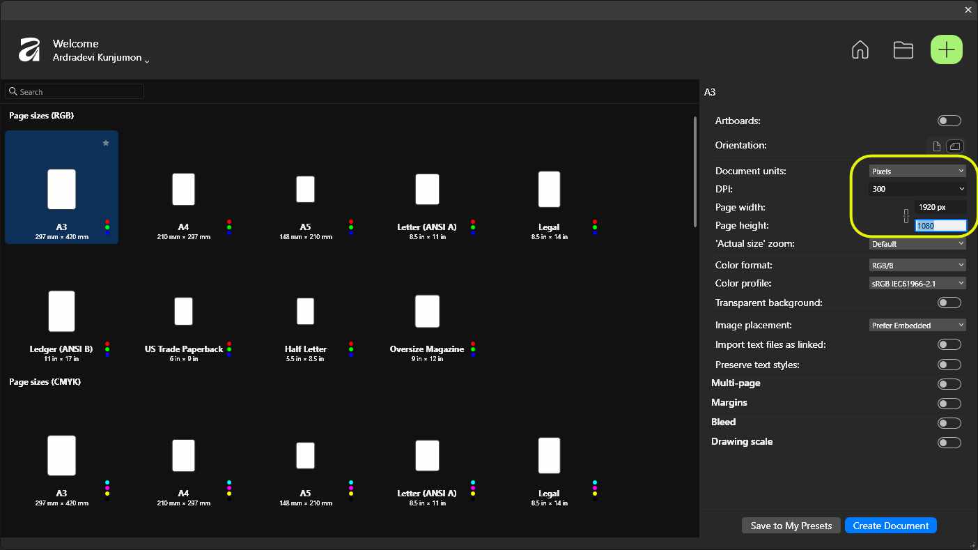
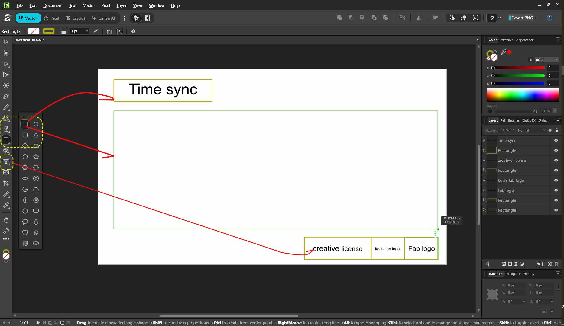
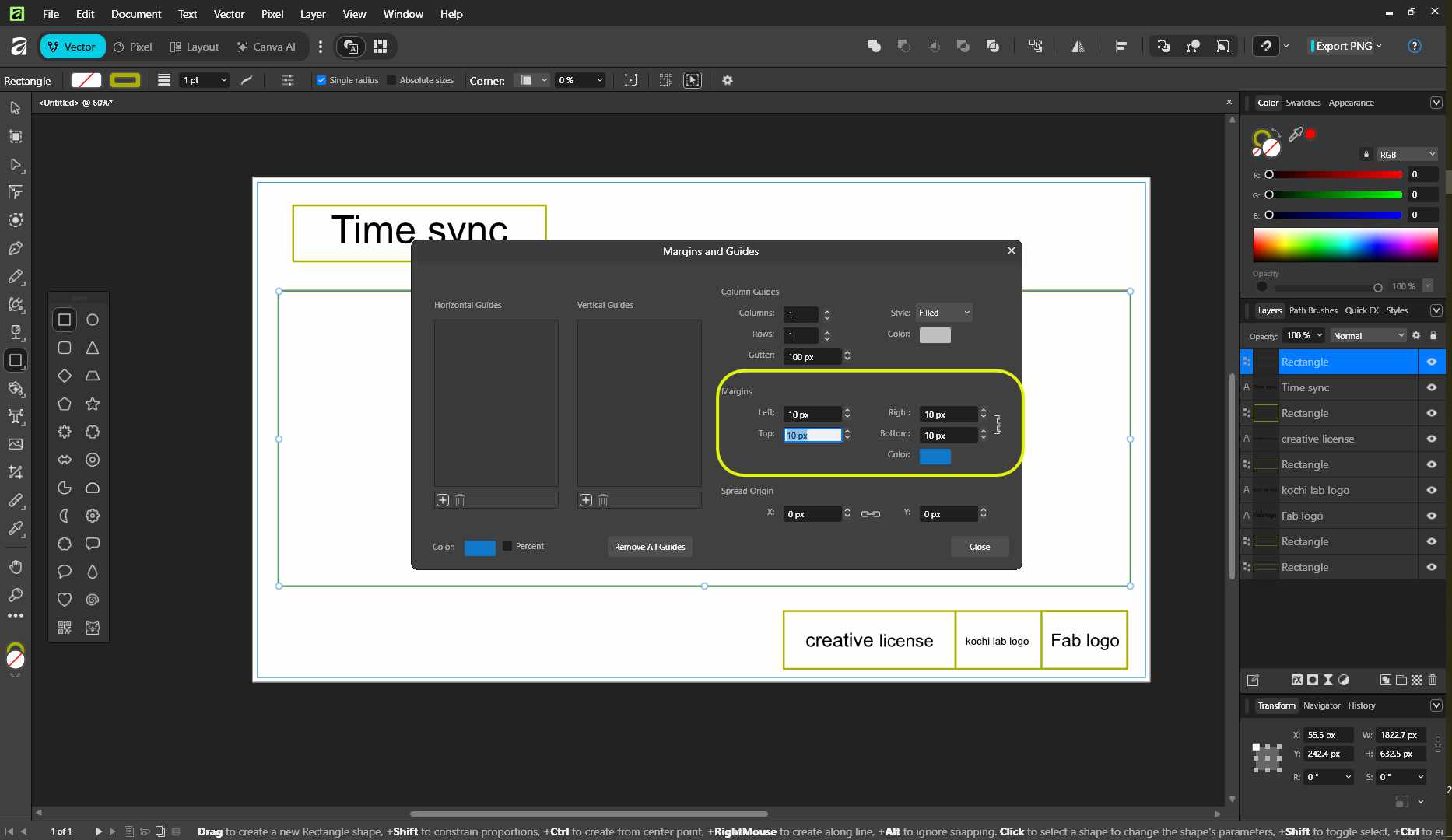
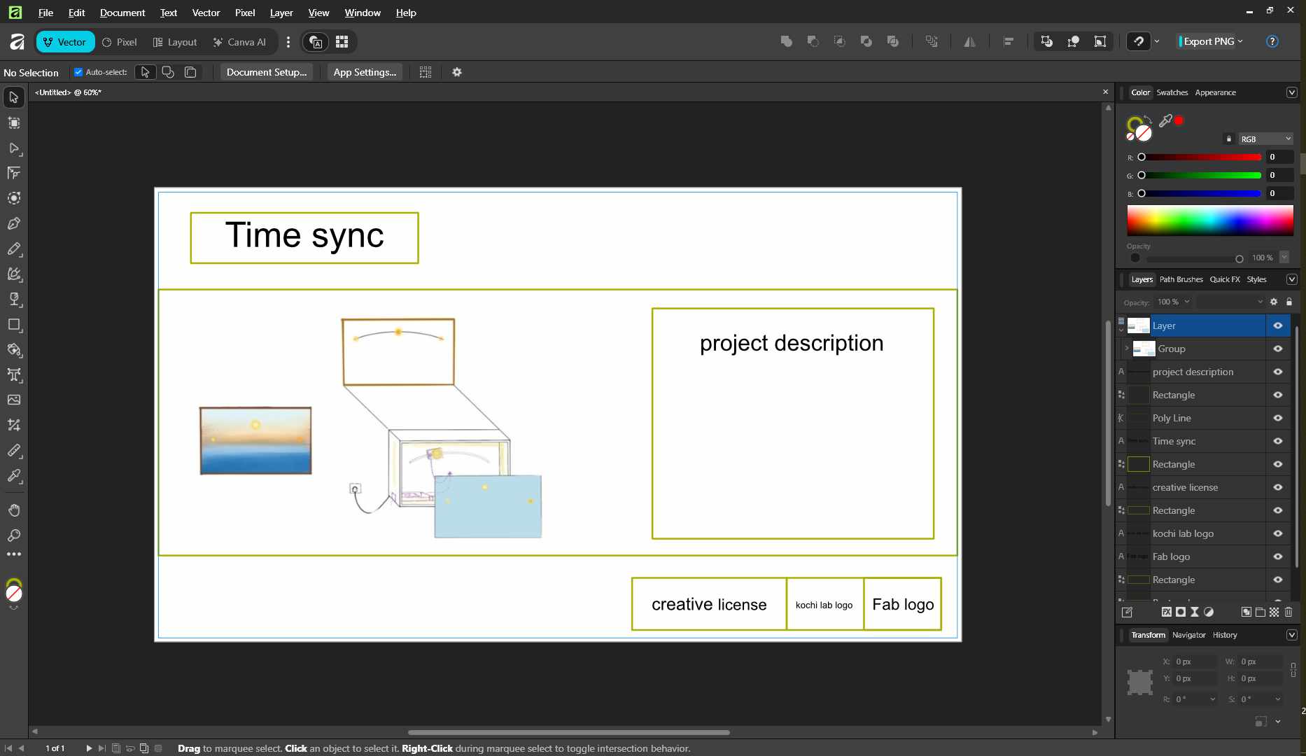
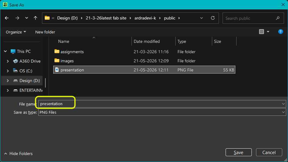
![To export the file. FILE > EXPORT or shortkey [Alt+Ctrl+Shift+w] Selct the PNG format from the left side panel. Make sure the size is still 1920x1080px . Click export and choose the file location to save.](../images/week-18/af5.jpg)
Final Project Presentation Draft Slide
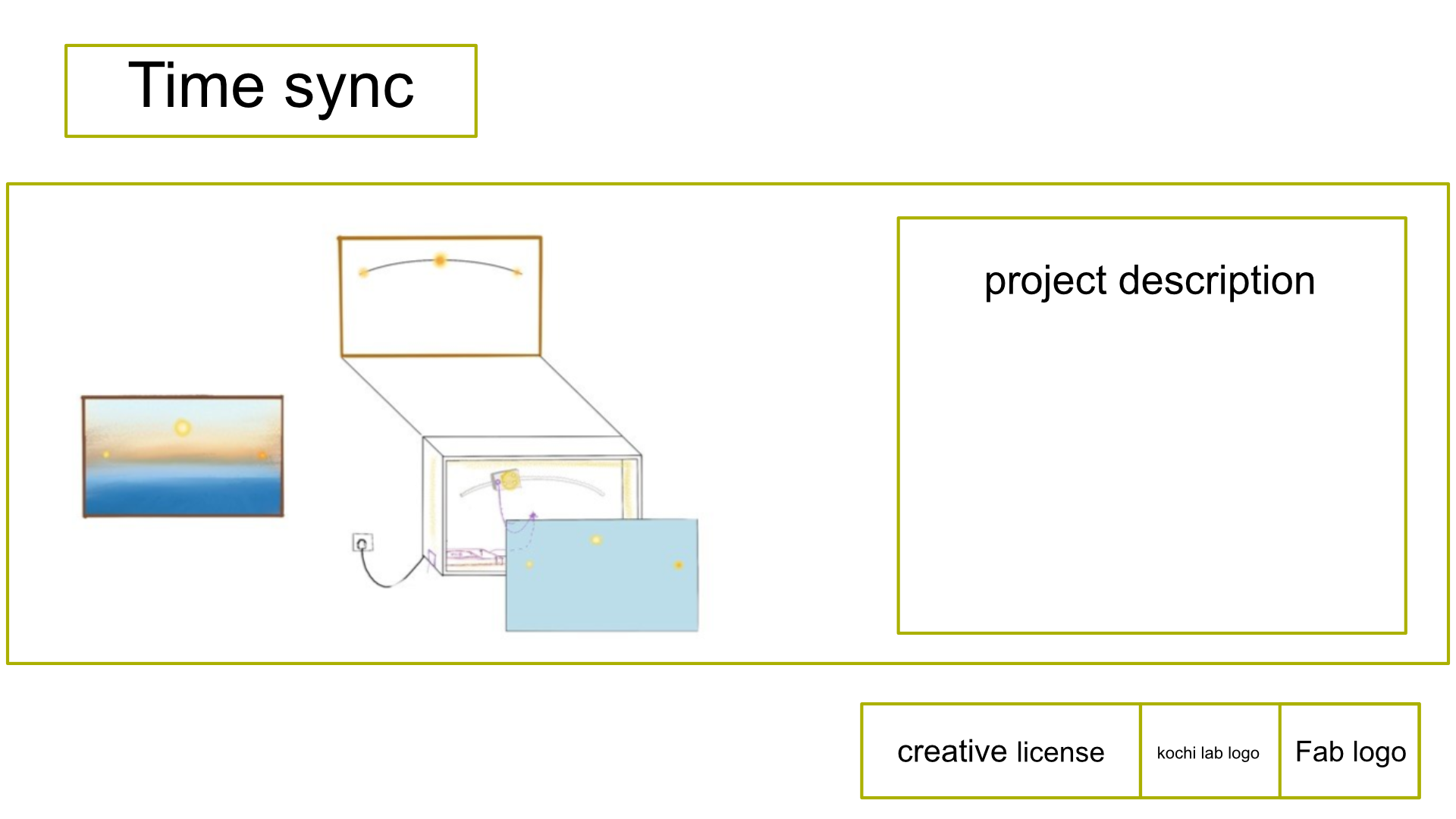
The draft of the presenantion.png slide that was added to the public folder.
VIDEO - Presenation.mp4 how to edit and add
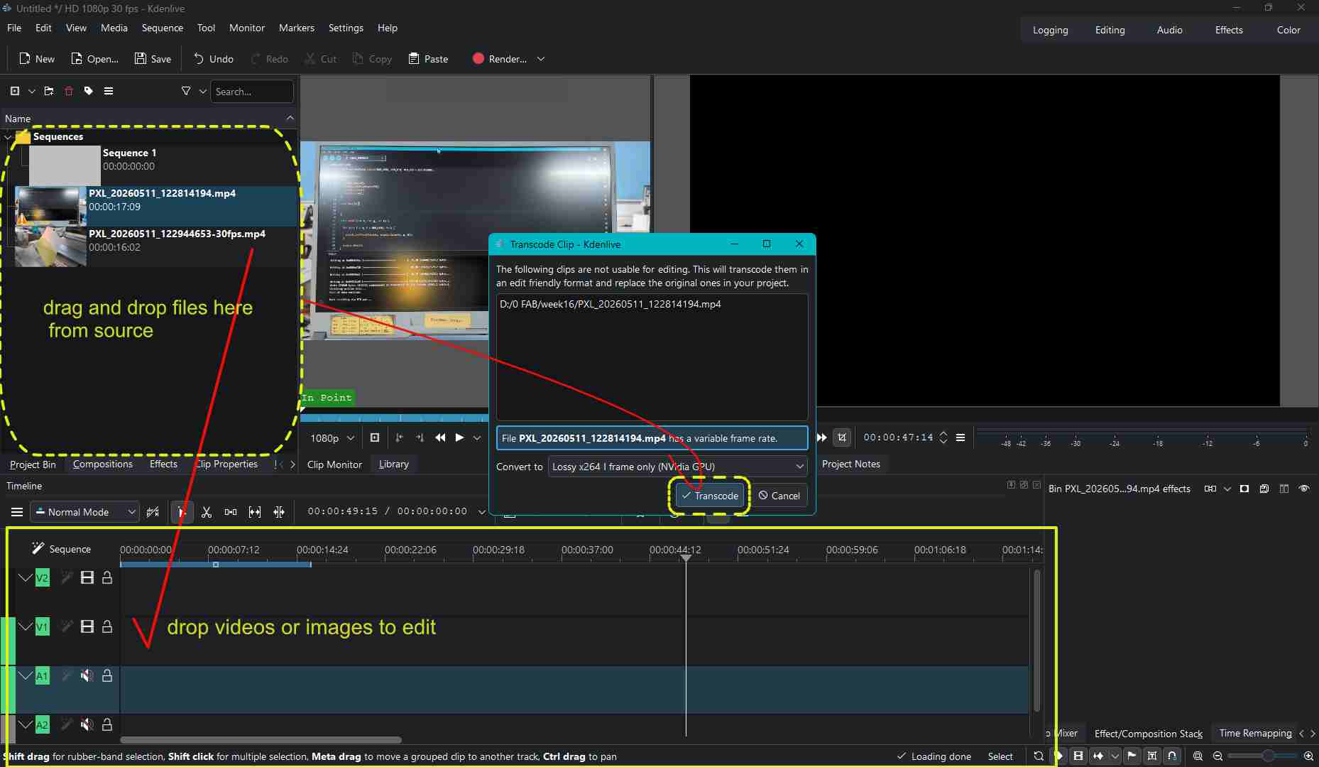
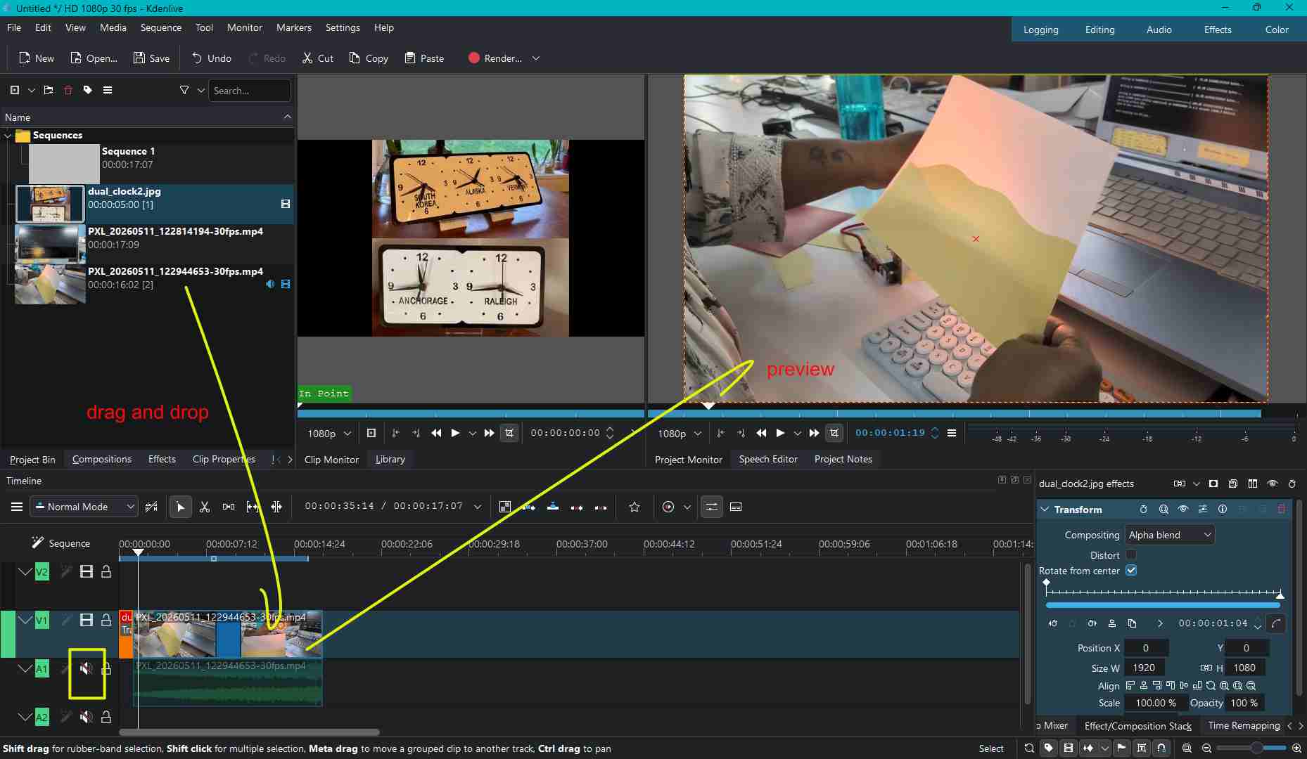
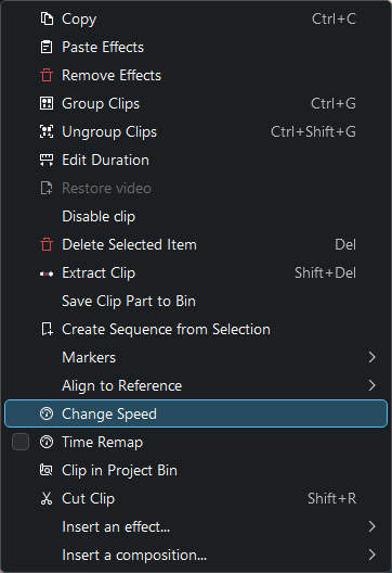
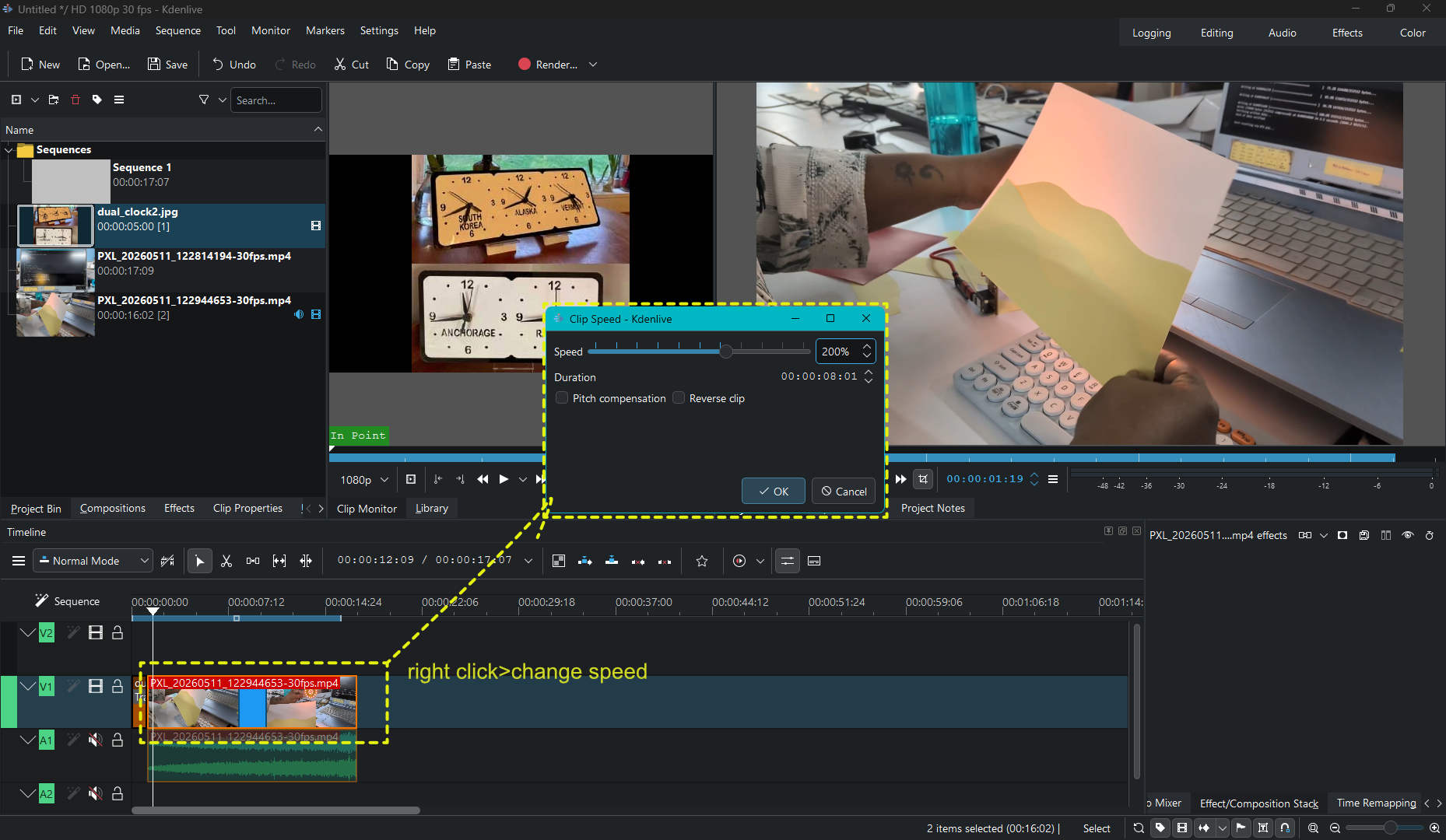
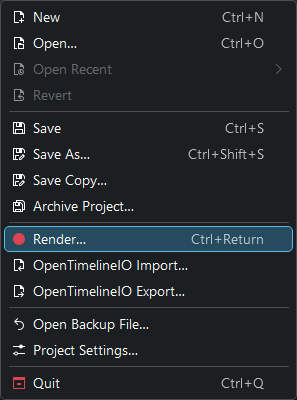
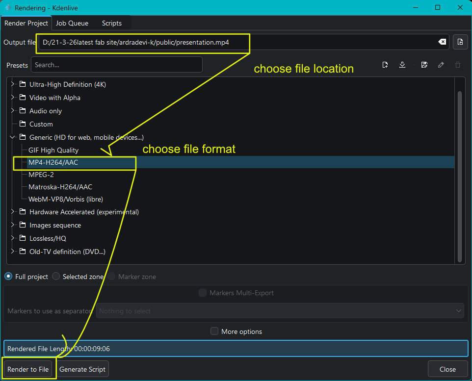
I tried to edit in Kdenlive. In Handbrake I tried to compress the video with presets shared in lab
Kdenlive ediitng
Handbrake- video compresser
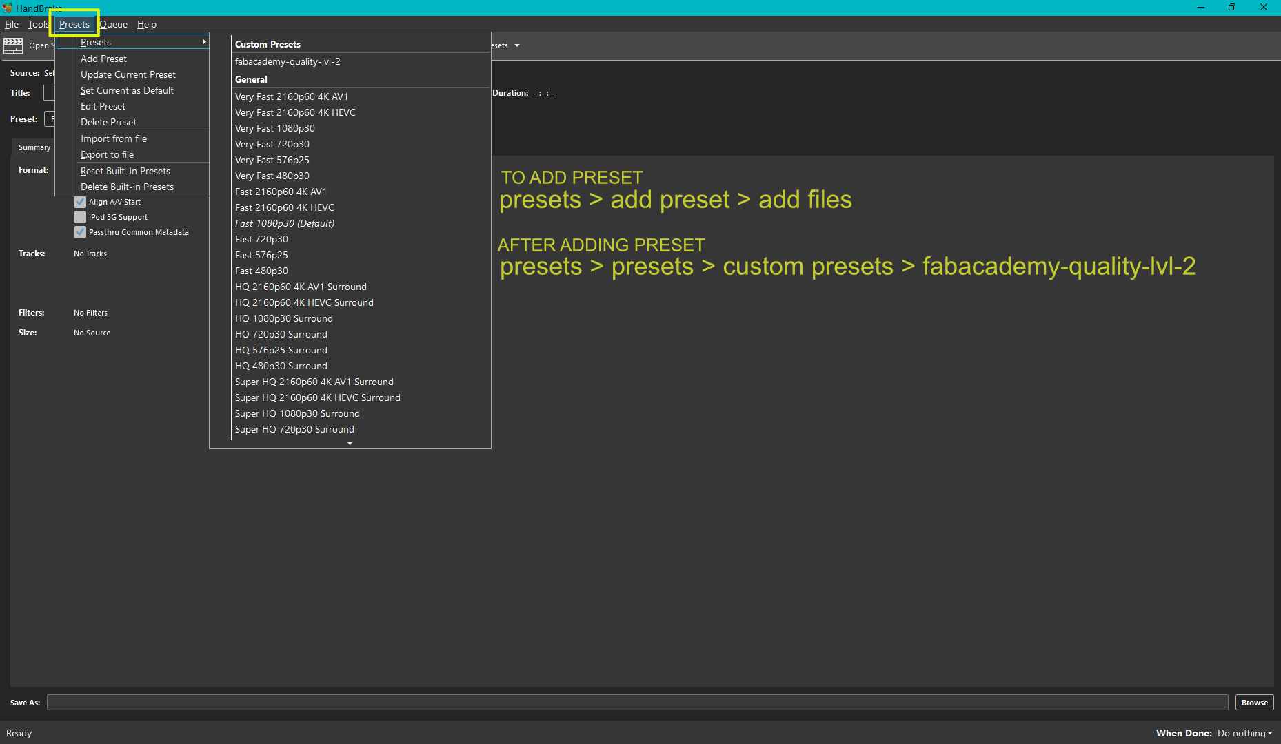
Final Project Presentation Draft Video
The draft of the presenantion.mp4 video that was added to the public folder.
Uploading the files
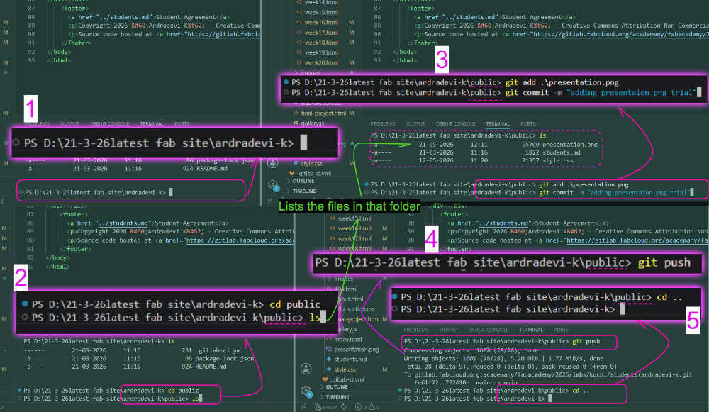
We can push specific files alone.
Usually, I push from this location: PS D:\21-3-26latest fab site\ardradevi-k>. So I am in the folder named ardradevi-k when I push the pages.
My pages are inside the assignments folder: ardradevi-k folder > public > assignments > week18.html.
My images and videos are inside that week's folder: ardradevi-k folder > public > images > week18.
When adding files in the VS Code terminal, it would look like this:
PS D:\21-3-26latest fab site\ardradevi-k> git add .
That space and dot mean to add everything. I just want to add a specific file.
I changed the folder from where I was pushing. For that, I have to change the location in VS Code.
PS D:\21-3-26latest fab site\ardradevi-k>
Enter cd public. Public is the name of the folder I want to be in, as the image and video are also there.
This changes PS D:\21-3-26latest fab site\ardradevi-k> to PS D:\21-3-26latest fab site\ardradevi-k\public>.
Enter ls, then git add .\presentation.png. You have to enter it exactly like this.
Then use the usual command:
git commit -m "adding presentation trial image"
Add a commit message you like, then run:
git push
After this, we have to go back to the original folder we were pushing from:
PS D:\21-3-26latest fab site\ardradevi-k>
Enter cd ...
This changes the current location from PS D:\21-3-26latest fab site\ardradevi-k\public> back to PS D:\21-3-26latest fab site\ardradevi-k>.


Before adding the slide and video. In the page it would look like this beside our name. "missing slide" here this person has added the video
This is how it would like, thought this is a screenshot after the final presentation.
Time Management
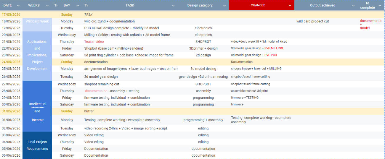
We started our schedule earlier, but I misjudged the time required for the tasks. I should have completed the PCB milling, but I was working on my Wildcard Week project until Wednesday. I had to catch up later. Created this table in Google Sheets.
More about project development is documented in THIS page.