WEEK 10
Output Devices
How the week started
Input device week did give an idea about how these devices work. So the output devices have been chosen after discussing with my instructor Sibin and Saheen.
How the week ended
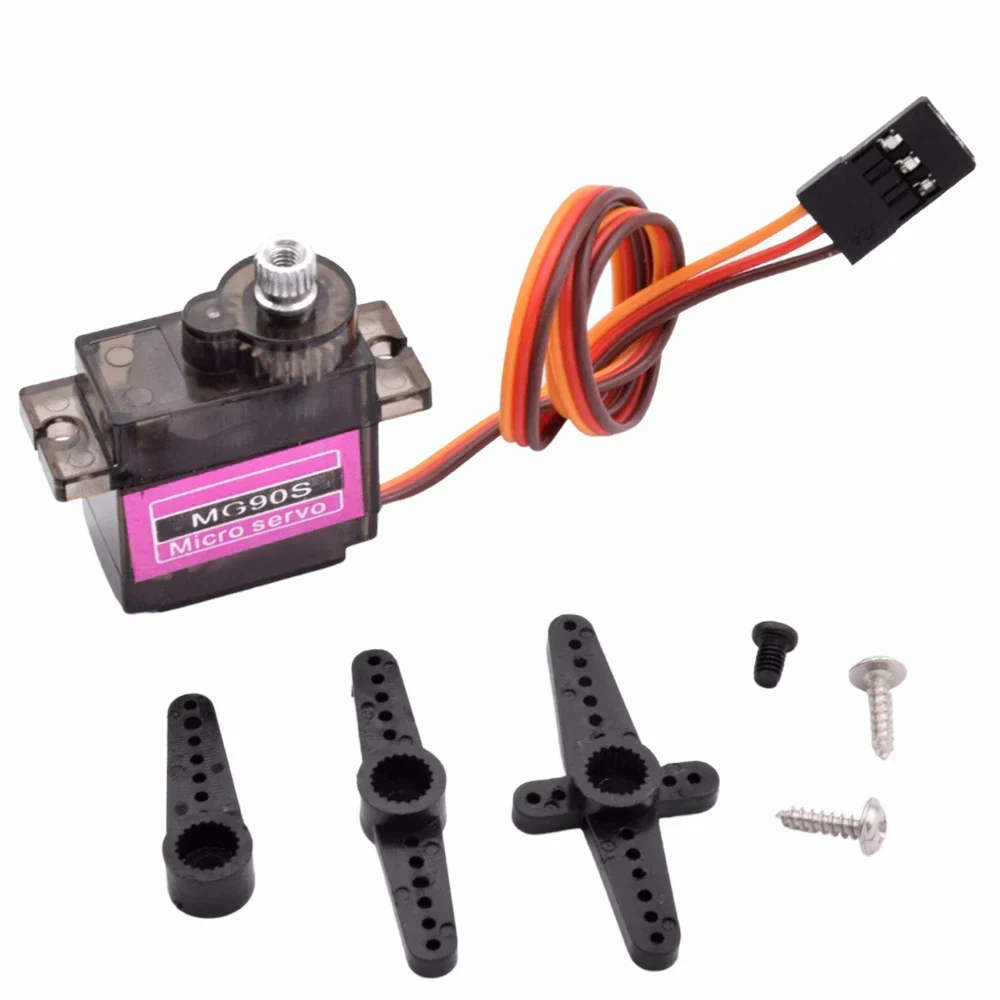
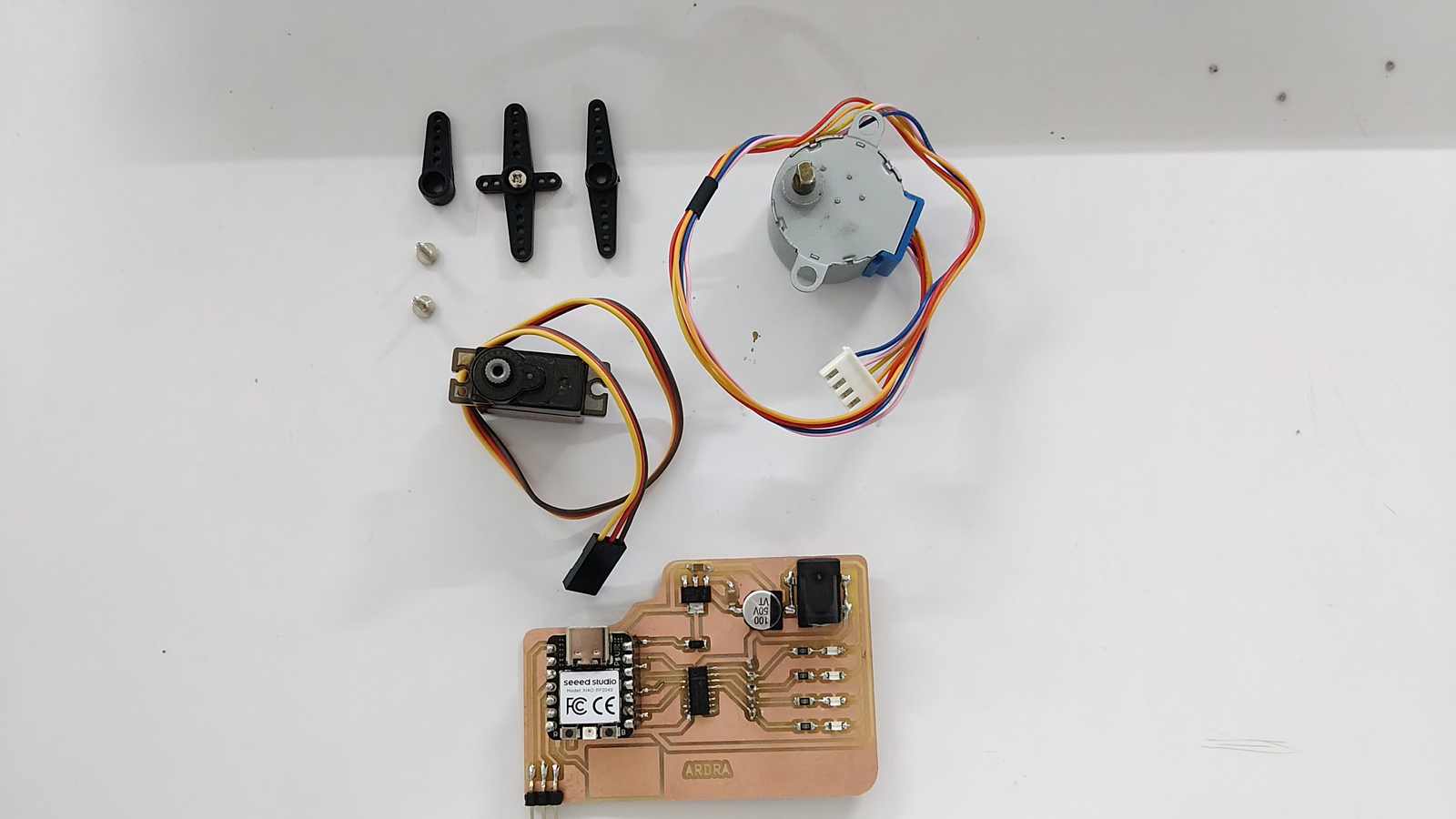
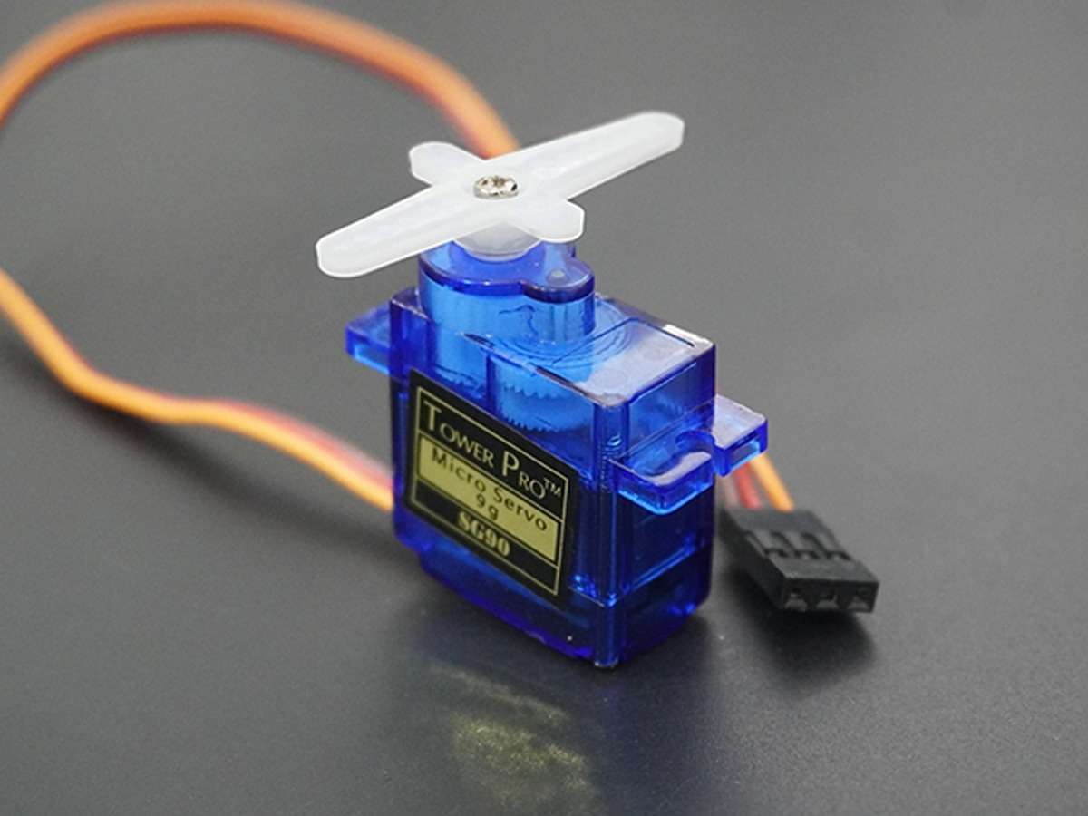
The week did start off well. As part of the spiral development, I chose to try out a servo motor and a stepper motor. A bit of planning would have been better on my side. I am yet to test the module.
Week 10’s Assignment
Group assignment:
- Measure the power consumption of an output device.
- Document your work on the group work page and reflect on your individual page what you learned.
Individual assignment:
- Add an output device to a microcontroller board you’ve designed and program it to do something.
Group assignemnt insight
We are calculating the power consumed by 3 NeoPixel lights (WS2812B). In NeoPixel lights, we can change the colors and the brightness. These affect the power consumption.
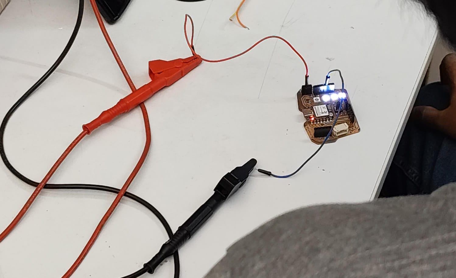
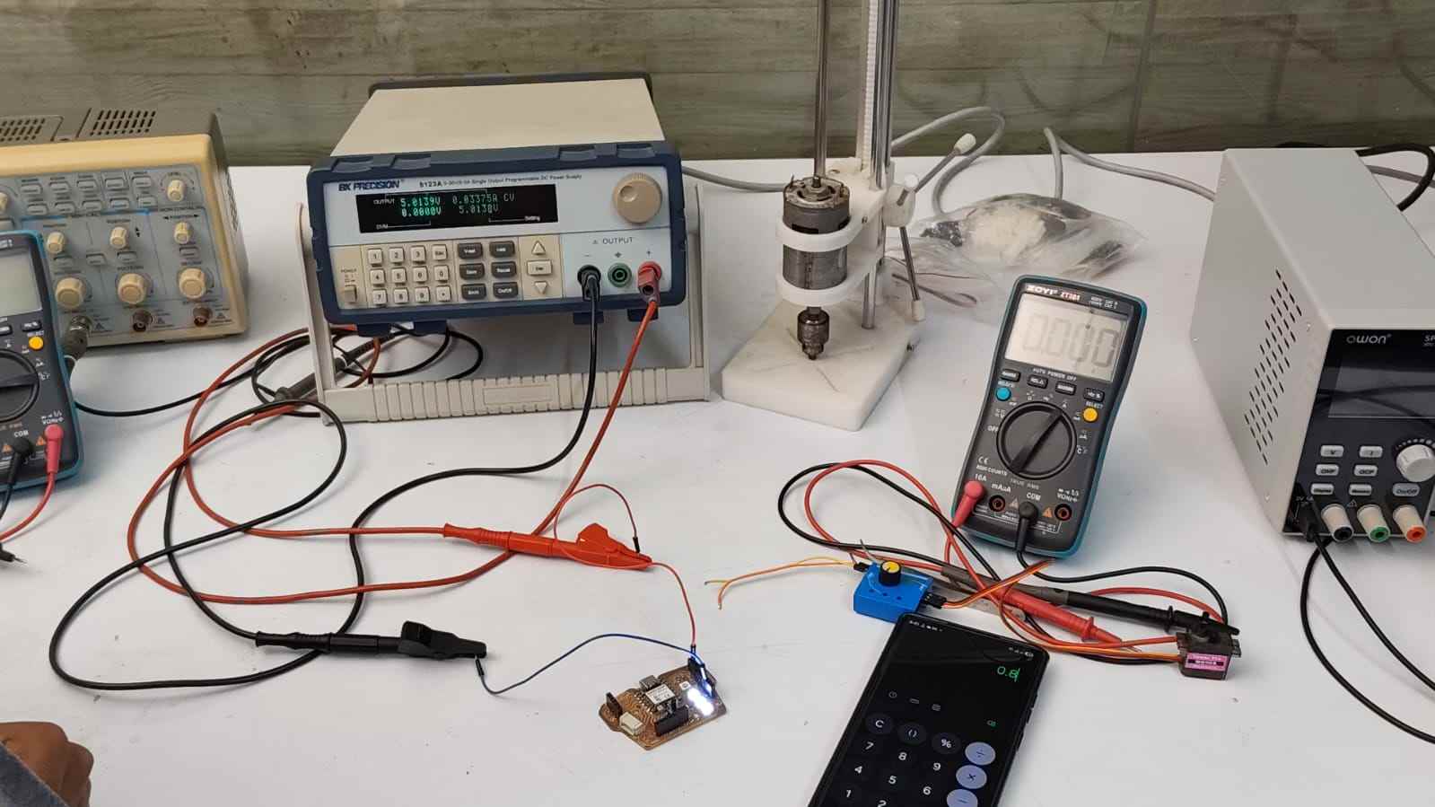
The board was programmed and then the NeoPixel was set to white light and 50/255 (20%) brightness level. The NeoPixels were powered from Bench Power Supply 9123A with a 5V supply voltage and 0.5A maximum current limit.
The probes were connected to the power and ground pins. A digital multimeter was used to measure the current consumption. The meter was set to current measurement mode. The probes connect the meter in series with the power supply to measure the current consumption. The measured current consumption was 0.0337A at a 5V input supply.
NeoPixel Power Consumption = Current × Voltage = 0.0337A × 5.0V = 0.16W
This means that if we want to run 20 NeoPixels for 3 hours, we will need 3.2Wh or about a 640mAh 5V battery.
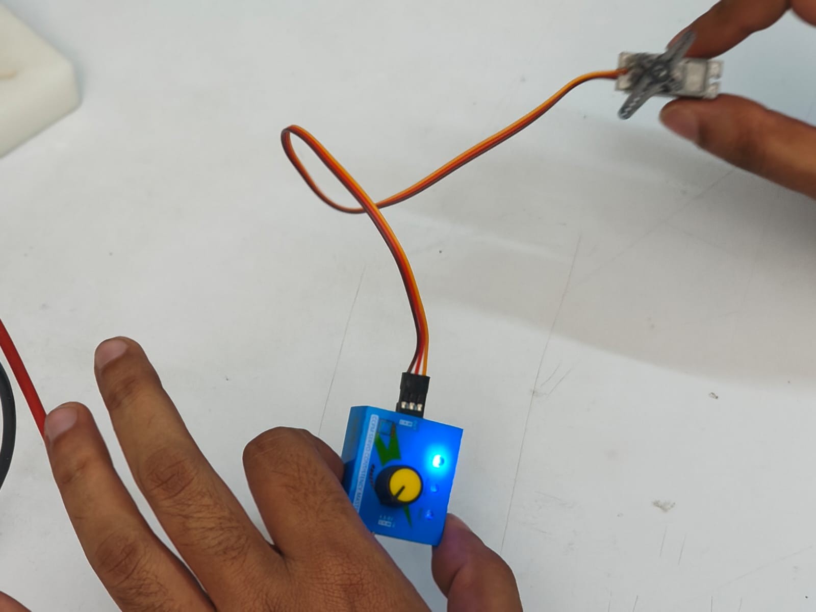
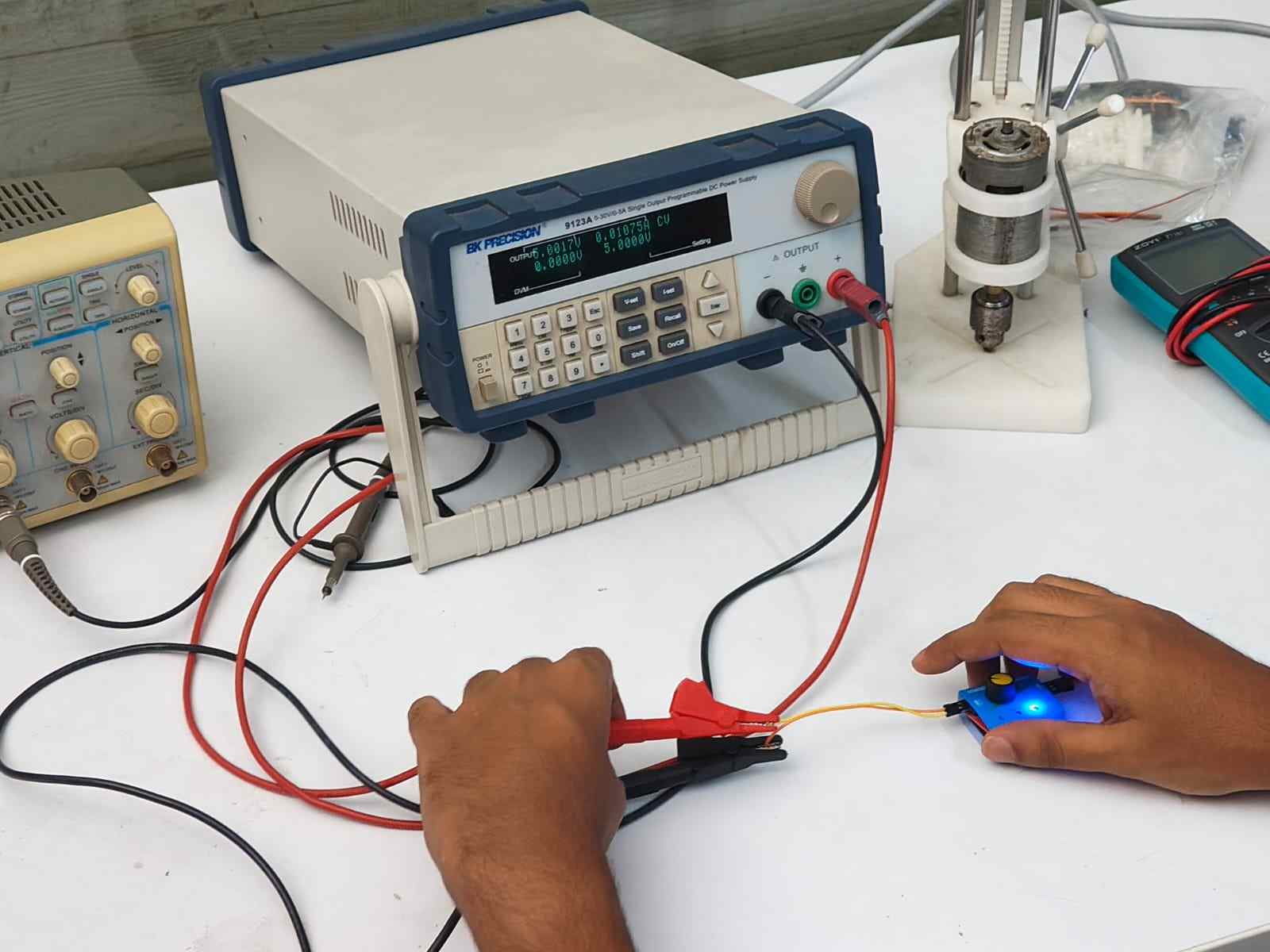
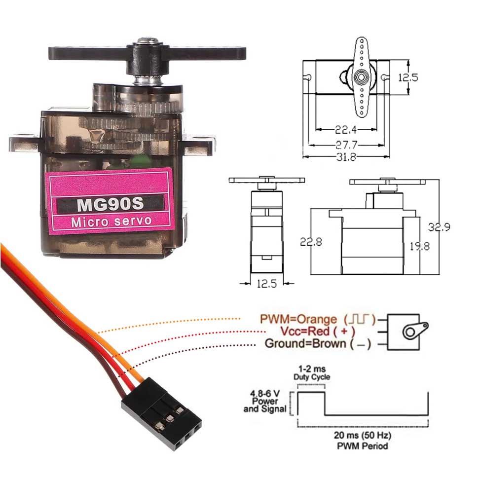
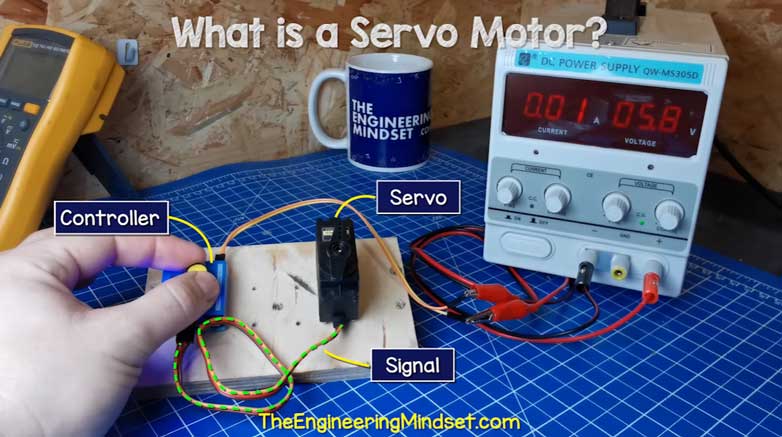
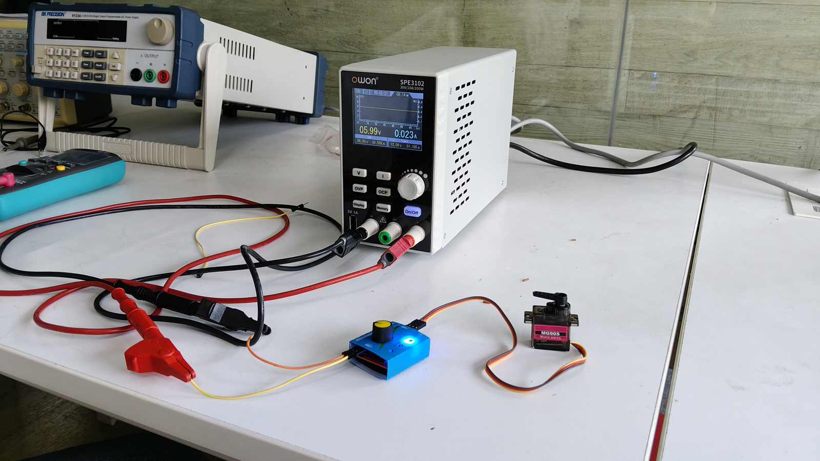
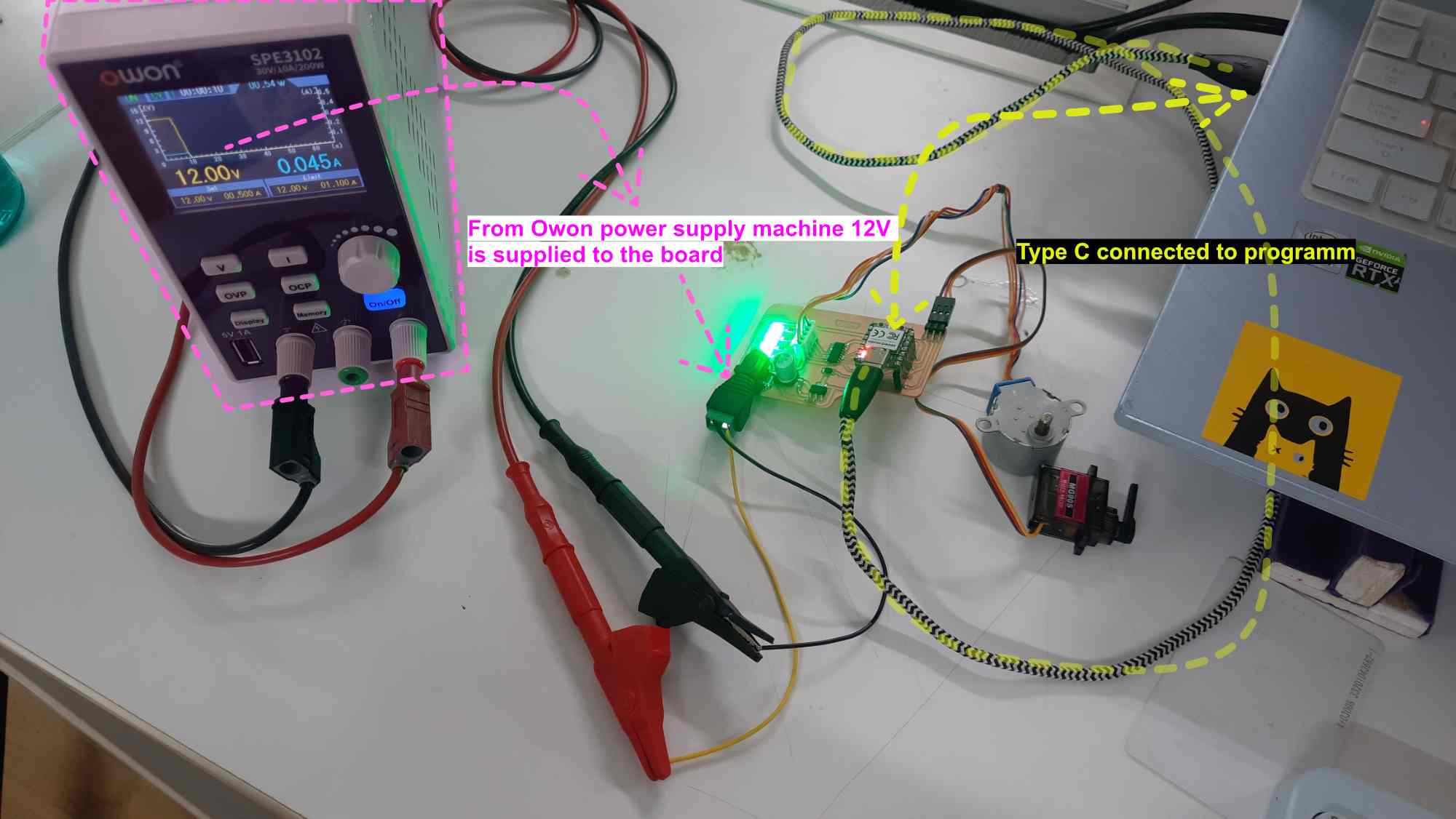
With a motor controller board, we powered the servo motor. With a 5V input supply, it consumed 0.011A of current.
Motor Power Consumption = Current × Voltage = 0.011A × 5.0V = 0.05W
If you scroll a bit above you could find the group link. In case you are feeling lazy to do so Here is the link to group assignment
Why I need an Output Device?
This week we are using devices that interact with us. In my final project I need the sun to move in a curved path. This movement of the light is linked to the time in the RTC. The RTC tells time to the microcontroller, then the light moves. This is the output part.
To do this movement I need a motor. There are stepper motors and servo motors.
My understanding of Output devices
How Electric Motors Work
What is a Motor?
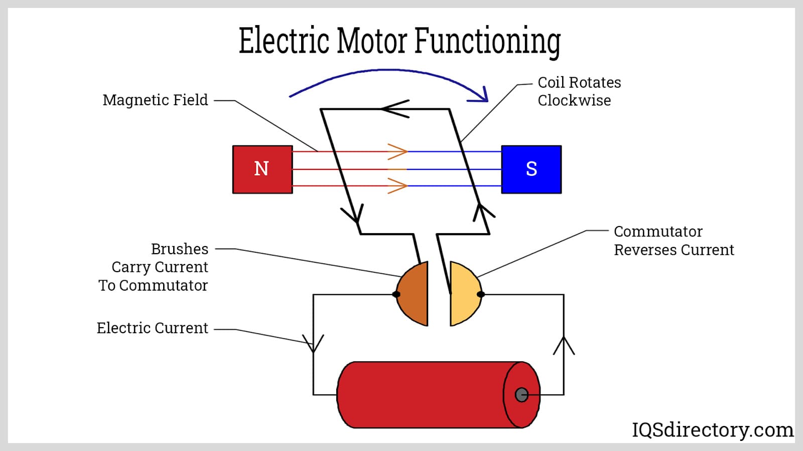
An electric motor converts electrical energy into mechanical energy, usually as rotational motion. There are two types of electric motors based on the type of current they use, the coil design, and the magnetic field created.
Image source ‖ An Introduction to Motors ‖ What is an Eelctric Motor? ‖ ‖ Youtube - How does an Electric Motor work? ‖
DC motors
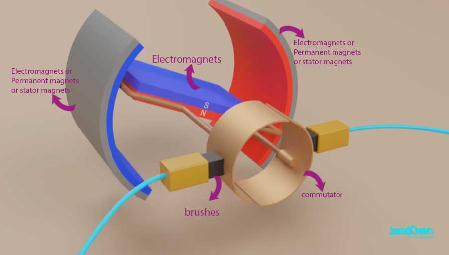
The DC motor works by direct current flowing to the commutator. The commutator is connected to the electromagnets. The electromagnets rotate as the polarity changes due to the current. The electromagnets are surrounded by permanent magnets. The rotation happens because of continuous switching of current direction through the commutator and brushes.
DC motors are of two types based on the commutation they use: brushed motor and brushless motor.
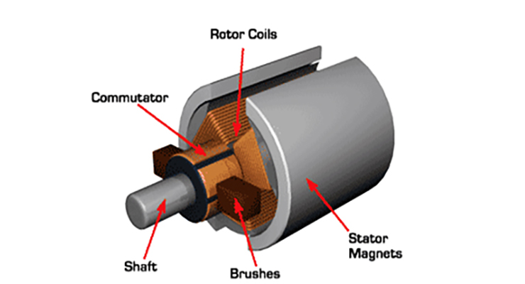
Brushed DC Motor
Dc Motors that use mechanical commutation , that is they use brushes as the mechanical contact. The current is delivered as the rotor turns, the brushes make contact with the commutor. These brushes stay in contact with the rotating part (Shaft).
BLDC - Brushless DC Motor
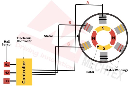
Dc Motors that use elctronic commutation are called Brushless DC motors (BLDC). As it operates without brushes it has high efficiency, long life, and precise control when compared to brushed dc motor.
- ESC (electronic speed controller) electronically commutates the motor by controlling the flow of current in the stator’s winding based on feedback from hall sensors.
- Hall sensor gives real time rotor position feedback, allowing the electronic controller to switch the stator coil current (commutation) at the precise moment for smooth, efficient operation.
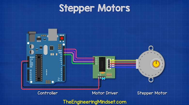 Image source
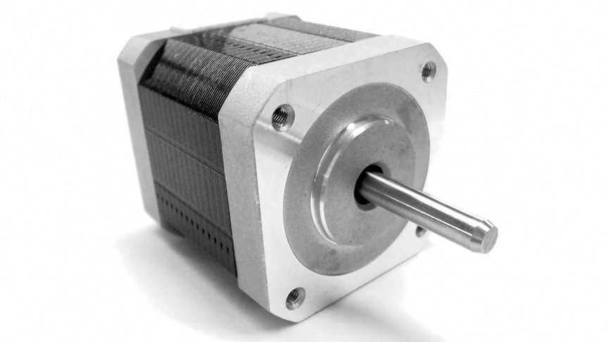
Stepper Motor
Stepper motors are a type of brushless motors. It is rotated by direct current. It is an electronic motor which rotates in steps rather than an continuous rotation motion. Since it rotates in steps it has larger number of magnetic poles.It divides a full rotation (360°) into a series of equal steps. This results in a step angle of 1.8°, which means each electrical pulse moves the shaft by exactly that amount.
Stepper motors have a relatively large torque, especially at low speeds .
Image source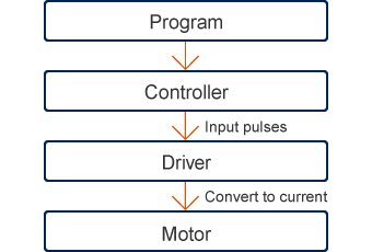
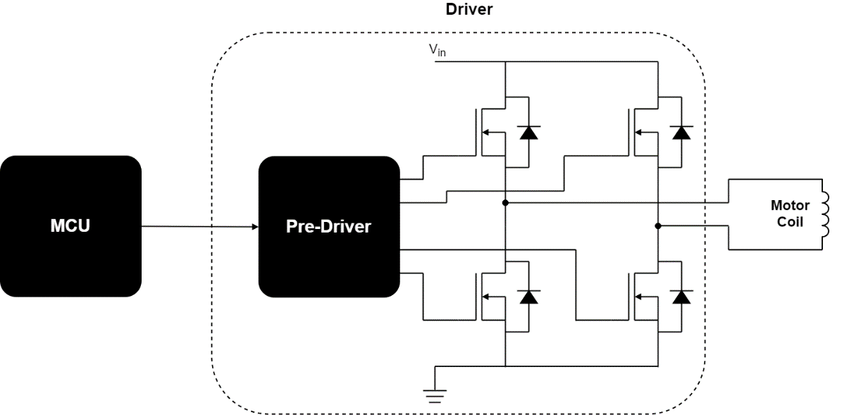
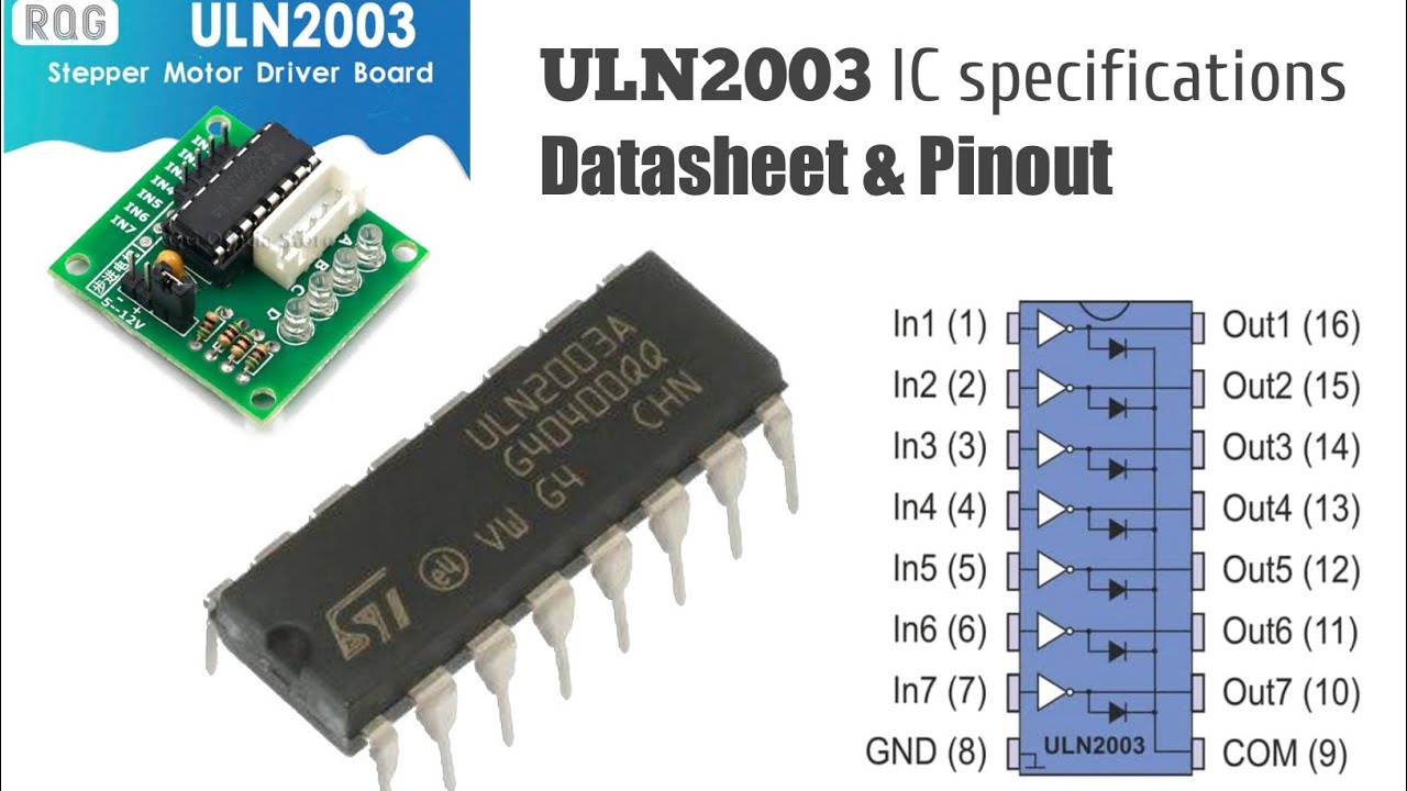
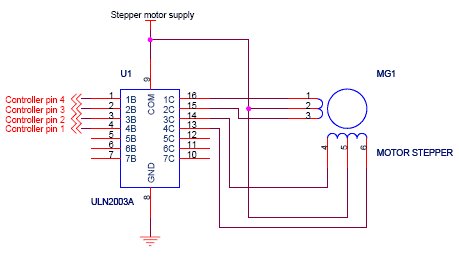
Stepper Motor + Driver
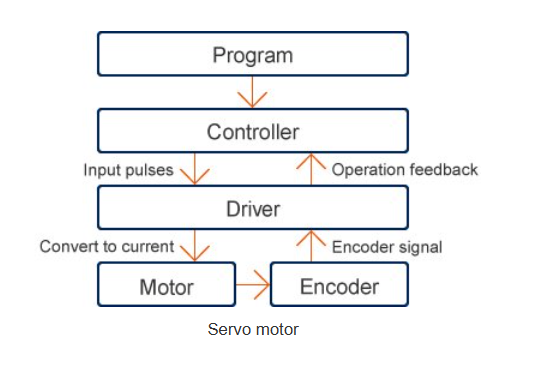
Stepper motors work based on the number of steps required for the motor to rotate. The number of steps can be called input impulses. The driver rotates the motor based on the number of steps it is instructed to move. The driver does not know the exact position of the motor, it only follows the given steps. Therefore, if there are any unexpected changes in the load or the device, the change in position of the rotation is not known by the driver.
Image sourceNote
Before you read more, let's see some terms.
Feedback device: This is a sensor on the motor which keeps note of its position in real time, speed, steps, and direction. For example, a rotary encoder. If this is the knob on a stereo player and I turn it clockwise, it would increase the volume, so this converts physical rotation to digital pulses.
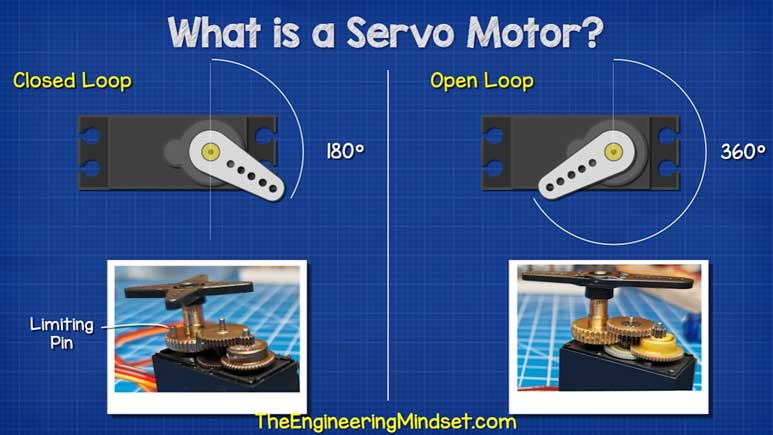
Open-loop system - NO feedback device If the motor is told to move 20 steps, and I happen to apply too much load on it, the motor may miss a few steps. The controller would have sent 20 pulses for it, but the load applied might have been too much to handle, and let's say it missed a few steps. The controller wouldn't know this.
Closed-loop system - WITH feedback device If the motor is to send out 20 pulses and only 16 steps are taken by the motor, the controller would get this report and send 4 more steps to complete the move to the correct position.
There are different types of stepper motors:
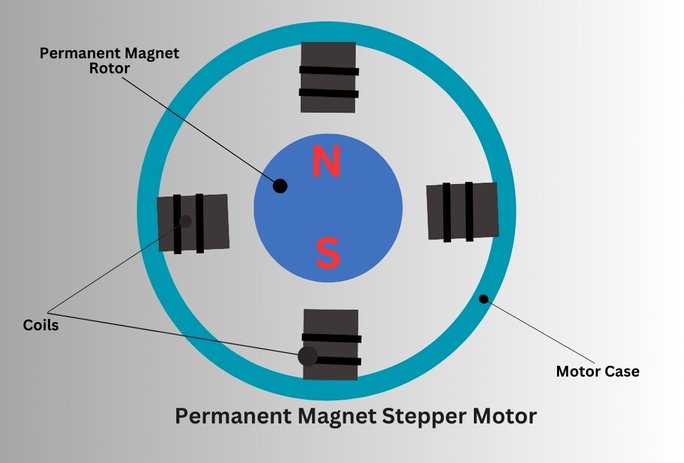
- Permanent Magnet (PM)
- Variable Reluctance (VR)
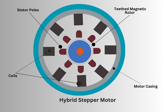
- Hybrid motors
Types of Stepper Motors

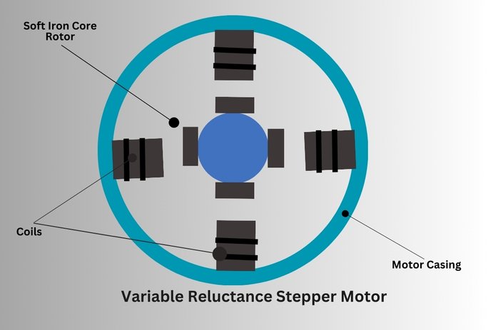

A hybrid stepper motor has a closed-loop system. This allows for precise control of the steps with help from the feedback device. All basic stepper motors run as open-loop by default.
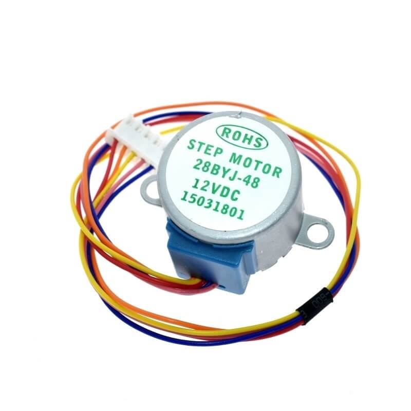
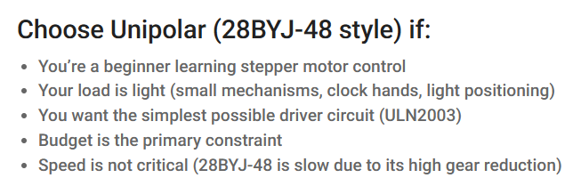
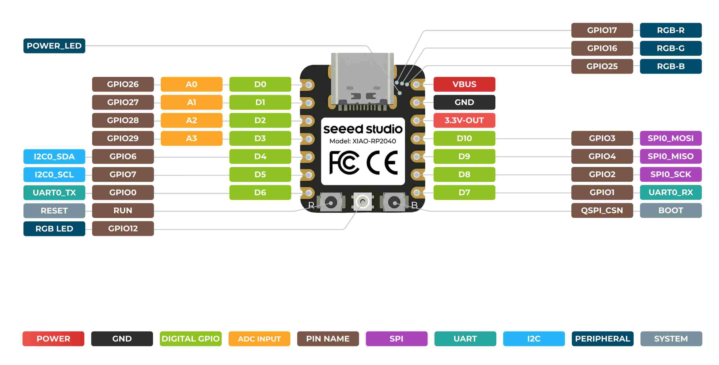
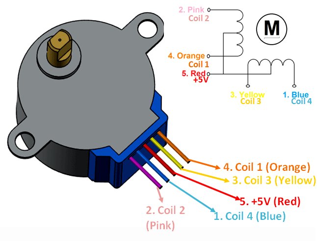
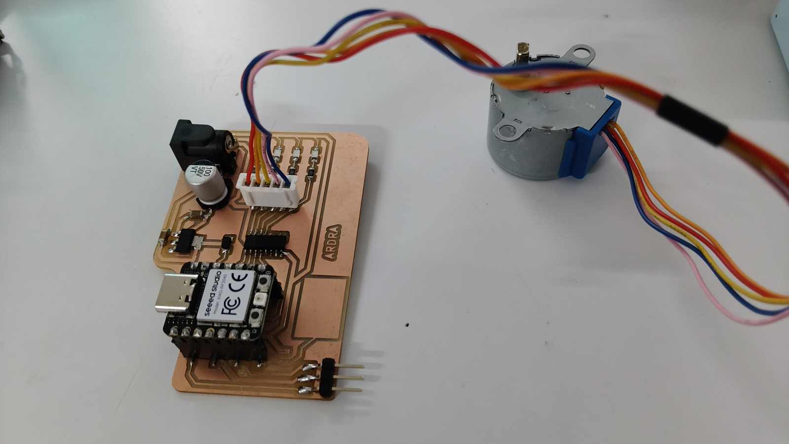
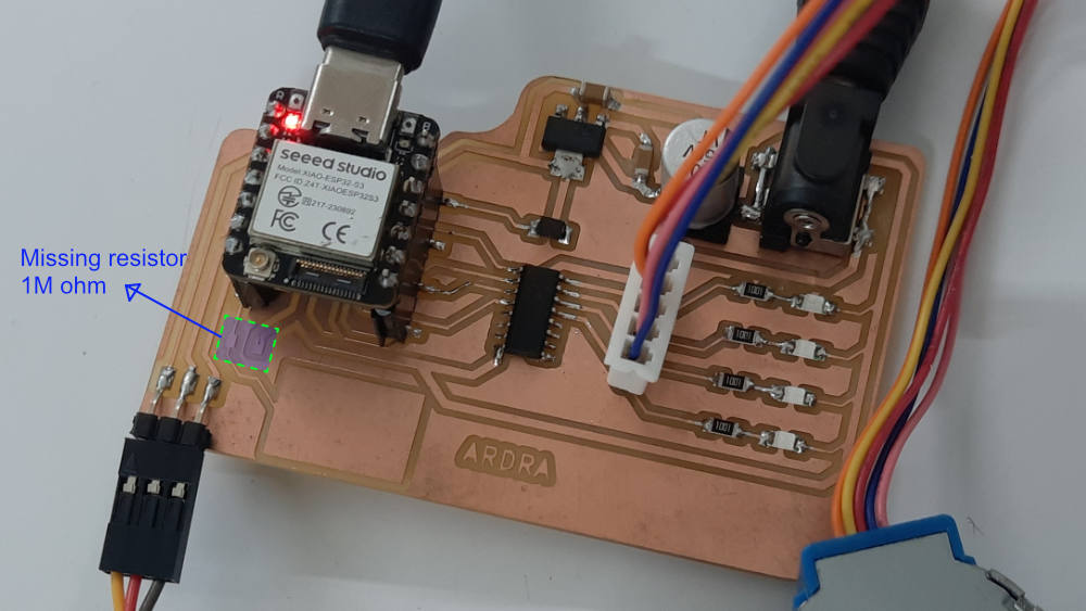
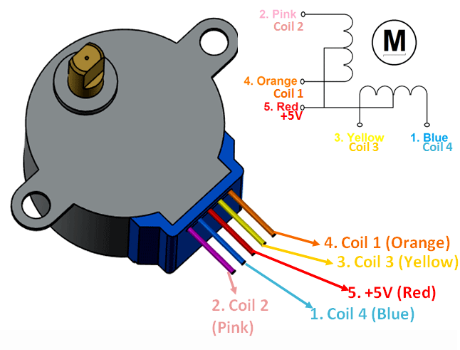
Motor used in board is 28BYJ-48 - 12V stepper motor Permanent Magnet (PM) stepper motor. - open-loop stepper motor.
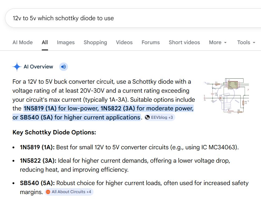
REFERNCE and Gemini interaction
‖ Stepper Motors ‖ ‖ Brushless DC Motors vs. Stepper Motors 1 ‖ ‖ Brushless DC Motors vs. Stepper Motors 2 ‖
.png)
.jpg)
.jpg)
.jpg)
.jpg)
.jpg)
.jpg)
.jpg)
.jpg)
.jpg)
.jpg)
.jpg)
.jpg)
.jpg)
.jpg)
.jpg)
.jpg)
.jpg)
.jpg)
.jpg)
.jpg)
.jpg)
.jpg)
.jpg)
.jpg)
.jpg)
.jpg)
.jpg)
.jpg)
.jpg)