Computer aided design is basically a language that the computer uses for the machine to give an output.
CAD is not limited to just 2D design. It involves 3d modeling too.
This week I have some basic understanding about 2d and 3d modelling softwares.
Still I am new to using Fusion and blender
Week 02’s assignment
• A possible final project's 2D and 3D models
• Compress the images and videos
• Post a description with your design files on the class page
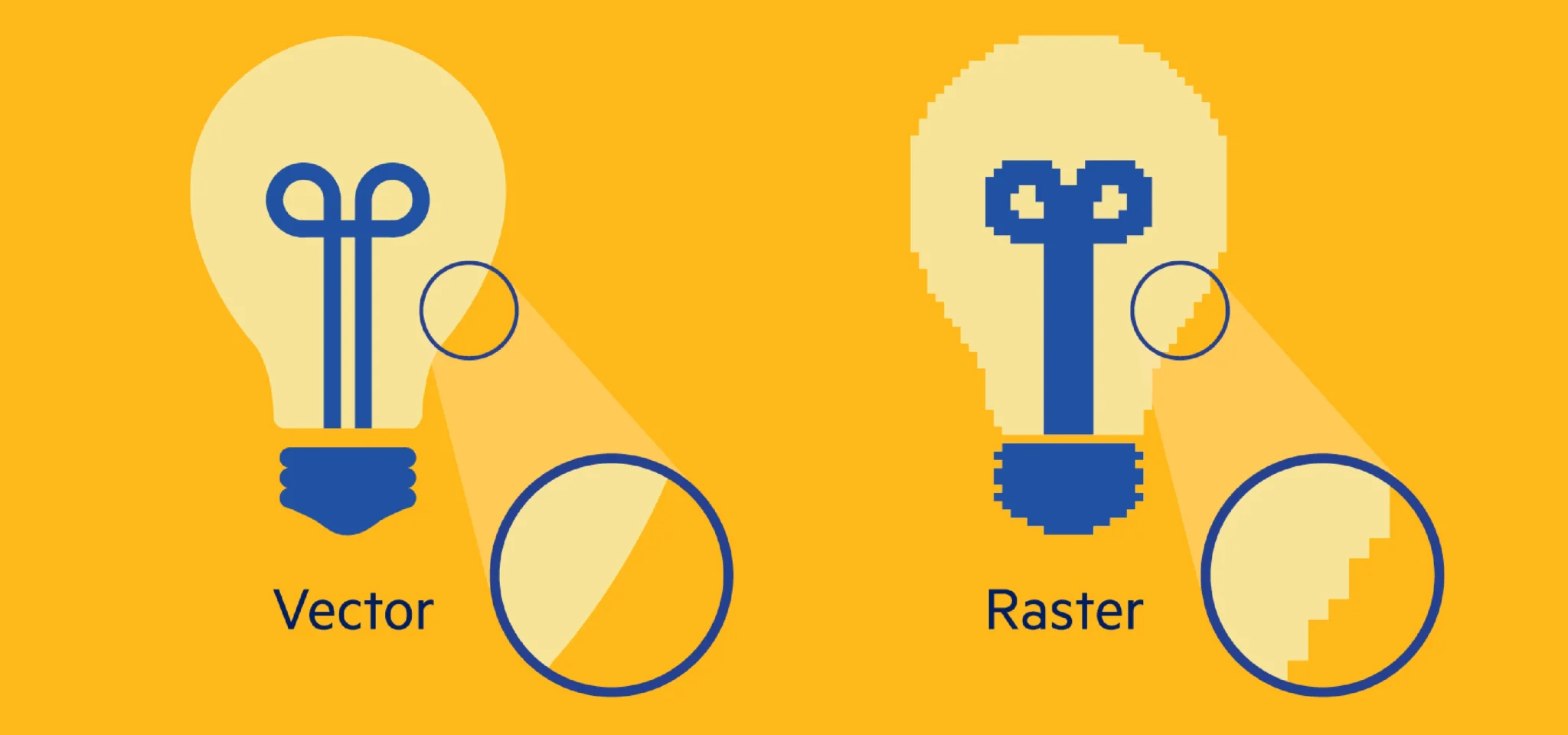
The very basics of 2D software is the use of vector and raster formats.
There are numerous software that can rasterize images. Vectors use mathematical
equations or codes to draw lines, making them very clear.
When scaled, vector images do not pixelate like raster images.
2D Software
Mostly we use 2D software such as Inkscape, Illustrator, Photopea, and Photoshop.
Vector image formats produce clean, precise lines that are suitable for laser cutting
and other digital fabrication processes.
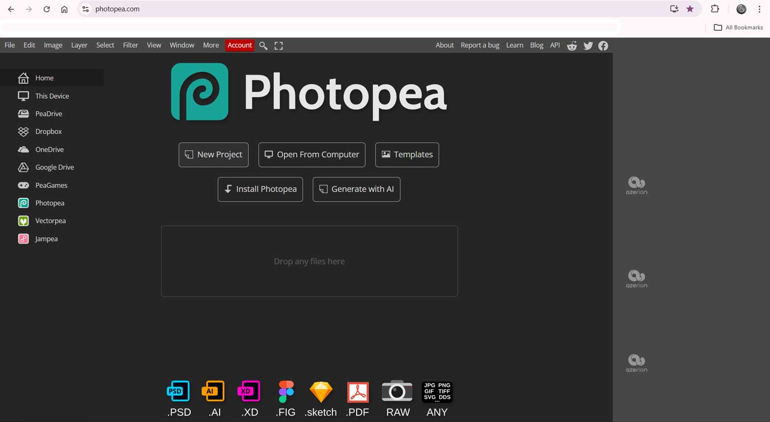
Photopea
Photopea is a browser-based open-source photo editing software that mainly works with raster images.
I opened the browser.
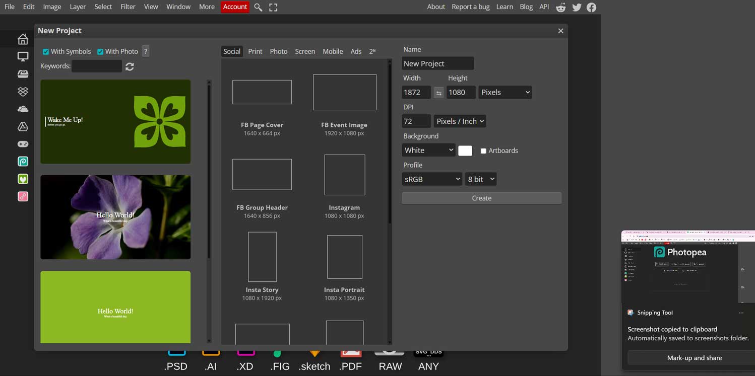
I was given options to create a new project or open an existing file from my system.
I chose to create a new file. The next page displayed different canvas sizes with
preset layouts as well as editable options.
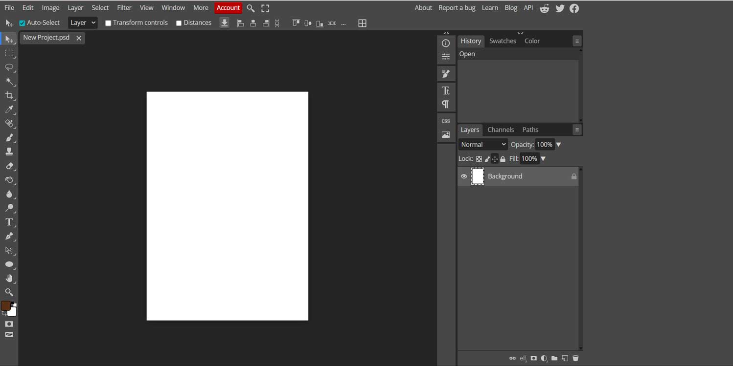
I selected an A4 canvas.
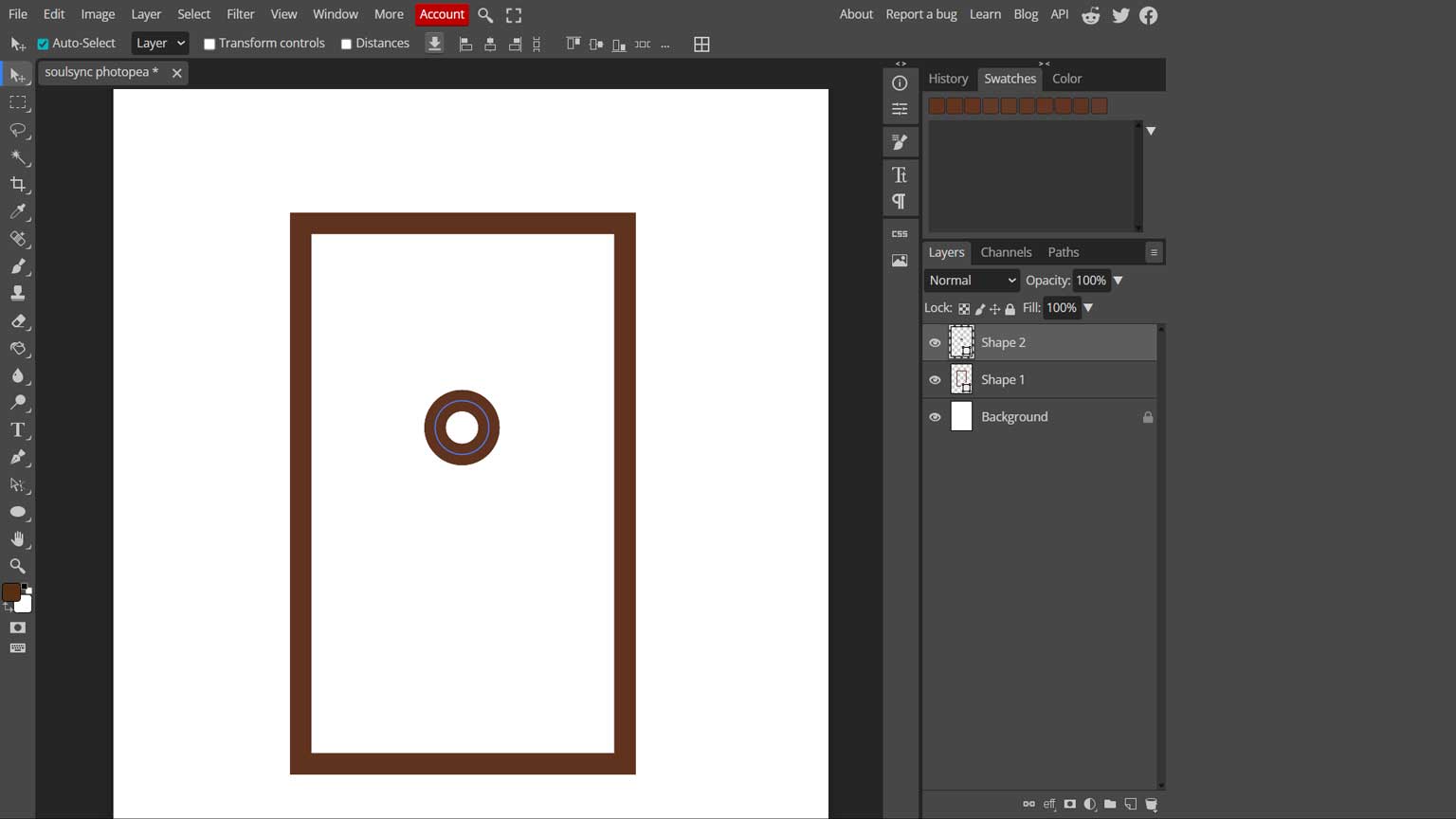
I created this by choosing the Rectangular Tool, or you can press ‘U’ on the keyboard.
Click and drag on the canvas to create the rectangle. Adjust the stroke to 20px (or as needed) from the ribbon bar.
I did not select any fill. You can also choose the color from the toolbar. To draw a circle,
click on the small arrow under the same tool and select the shape you want to create.
You aslo work in layers
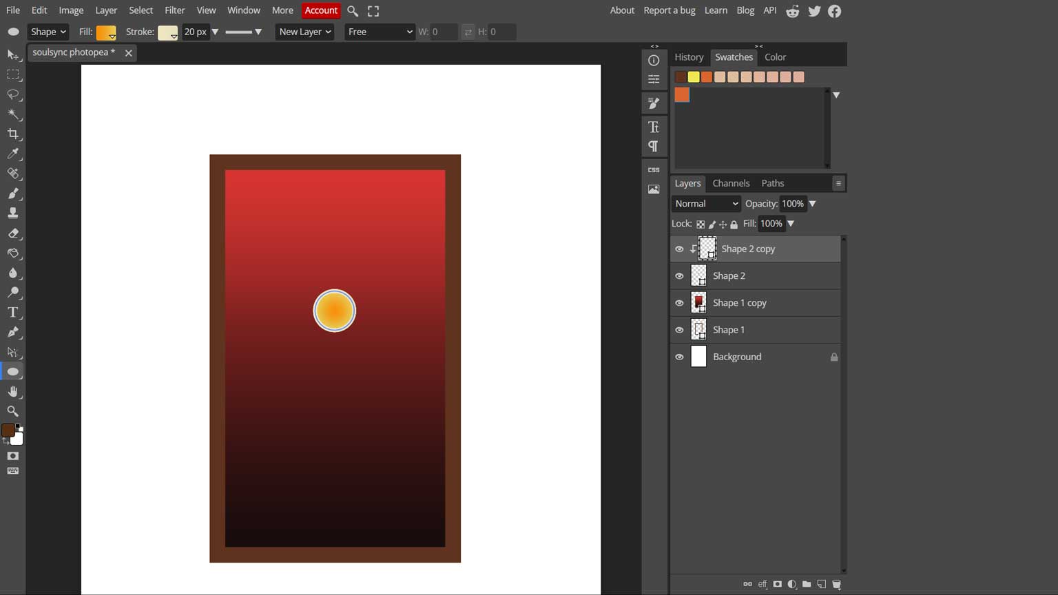
Here, I used the Fill Tool to pick the colors. You can also adjust the blending
options in the bottom-right corner of the Layers panel
Inkscape
Inkscape is a free
and open-source vector graphics software available for Windows, macOS, and Linux. It is used to create drawings such
as logos, illustrations, diagrams, cartoons, and charts. Because it uses vector graphics, images can be resized
without losing quality. Inkscape saves files in SVG format, which can be opened in many other programs and web browsers.
Photoshop has been my go-to editing software for composing presentations, and Photopea is very similar to it. However, both of these
are raster-based softwares. When it comes to laser cutting and making files easy for machines to understand, we have to rely on
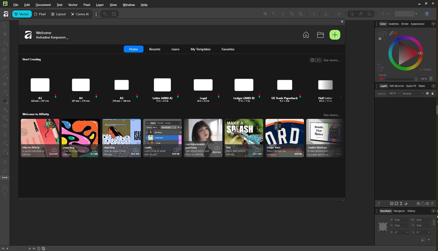
vector-based softwares like Adobe Illustrator or the open-source software, Inkscape. Affinity is another software that is a
blend of both types. I used Inkscape to try bitmap tracing.
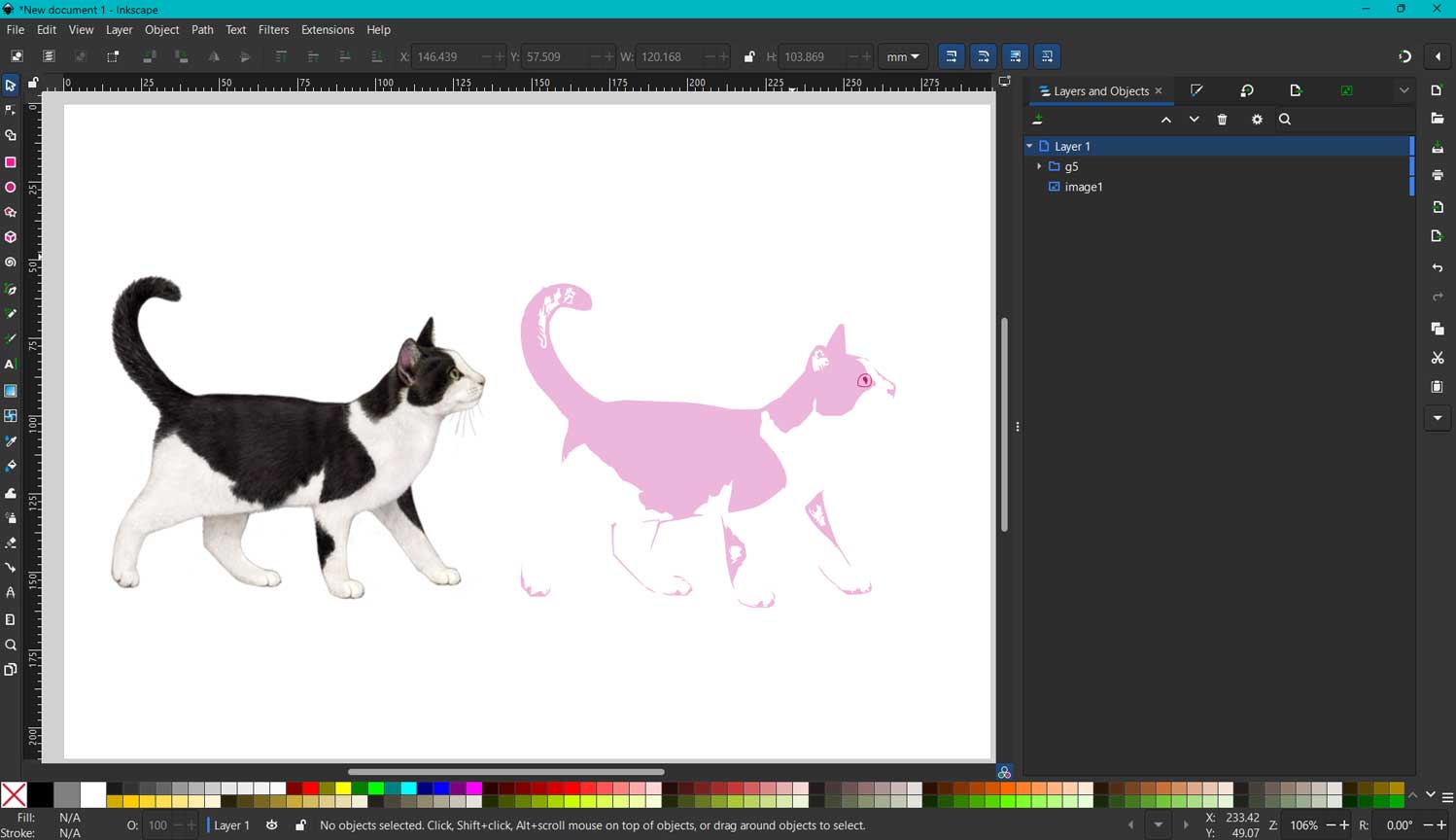
Inkscape also has a similar layout to other editing and 3D softwares. I chose an A5 template to work on.
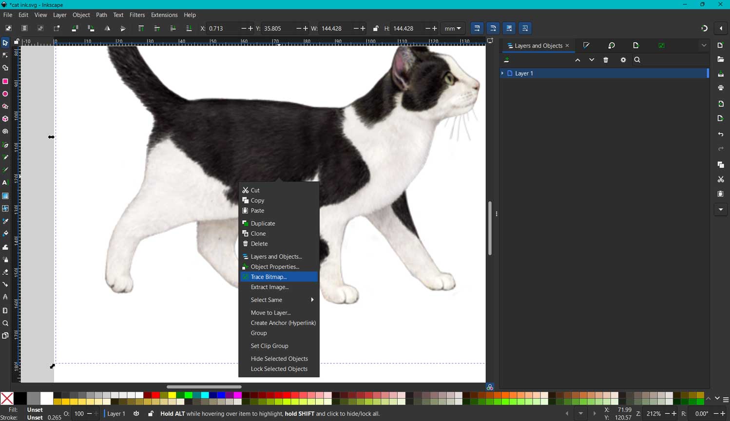
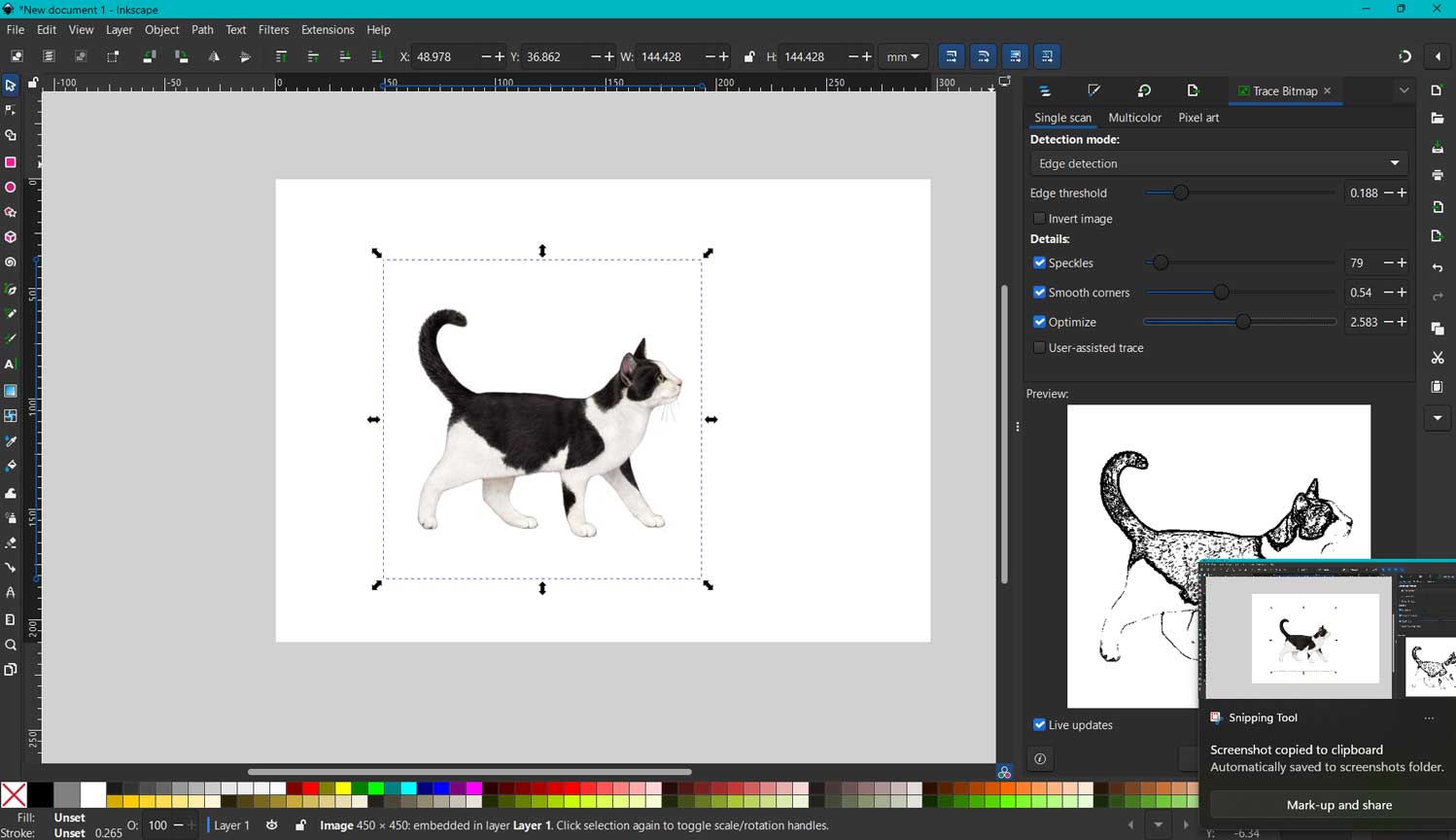
I dragged and dropped an image from the internet. The image had a clean outline.
I right-clicked with the mouse. In the dialog box, I selected “Trace Bitmap.”
A Trace Bitmap properties dialog box opened.
I chose “Edge Detection” and adjusted the threshold to keep some features of the fur.
I also smoothed the edges. There is a preview box that shows the changes,
so we can finalise the result.
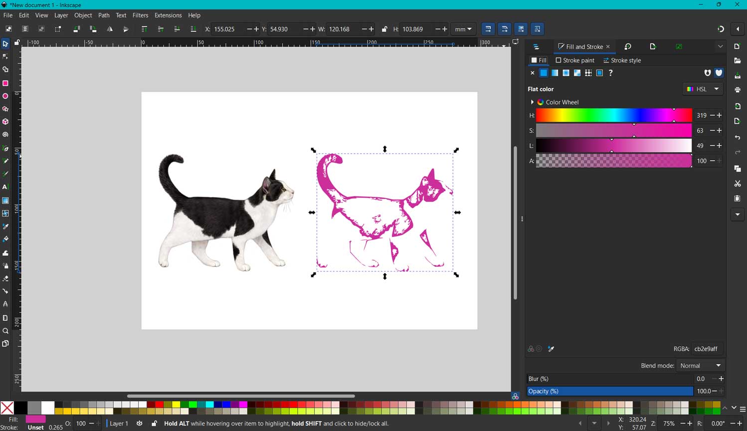
I selected the “Nodes” tool. This helps to adjust the shapes. I chose to change
the color of the trace and its transparency.
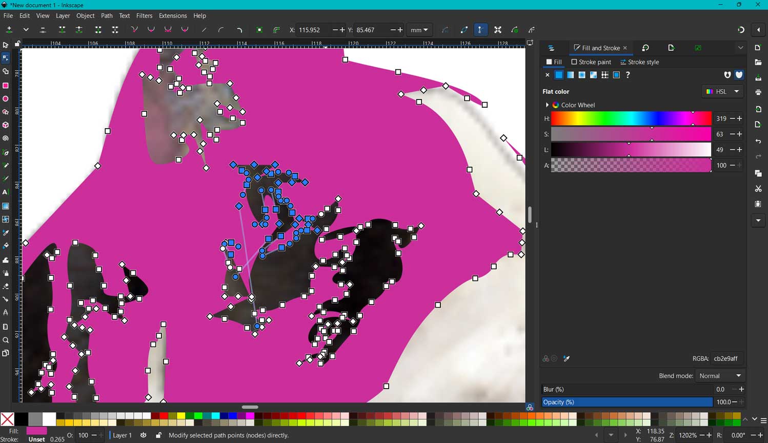
I selected many unwanted nodes and deleted them so I could get a clean filled image.
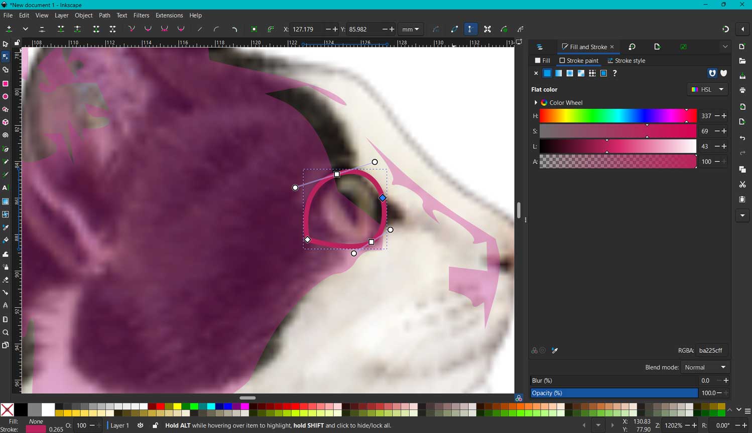
I outlined the cat’s eye using the pen tool. With this tool, we can
draw straight lines and curves and adjust them easily.
The thickness and stroke size can also be changed.
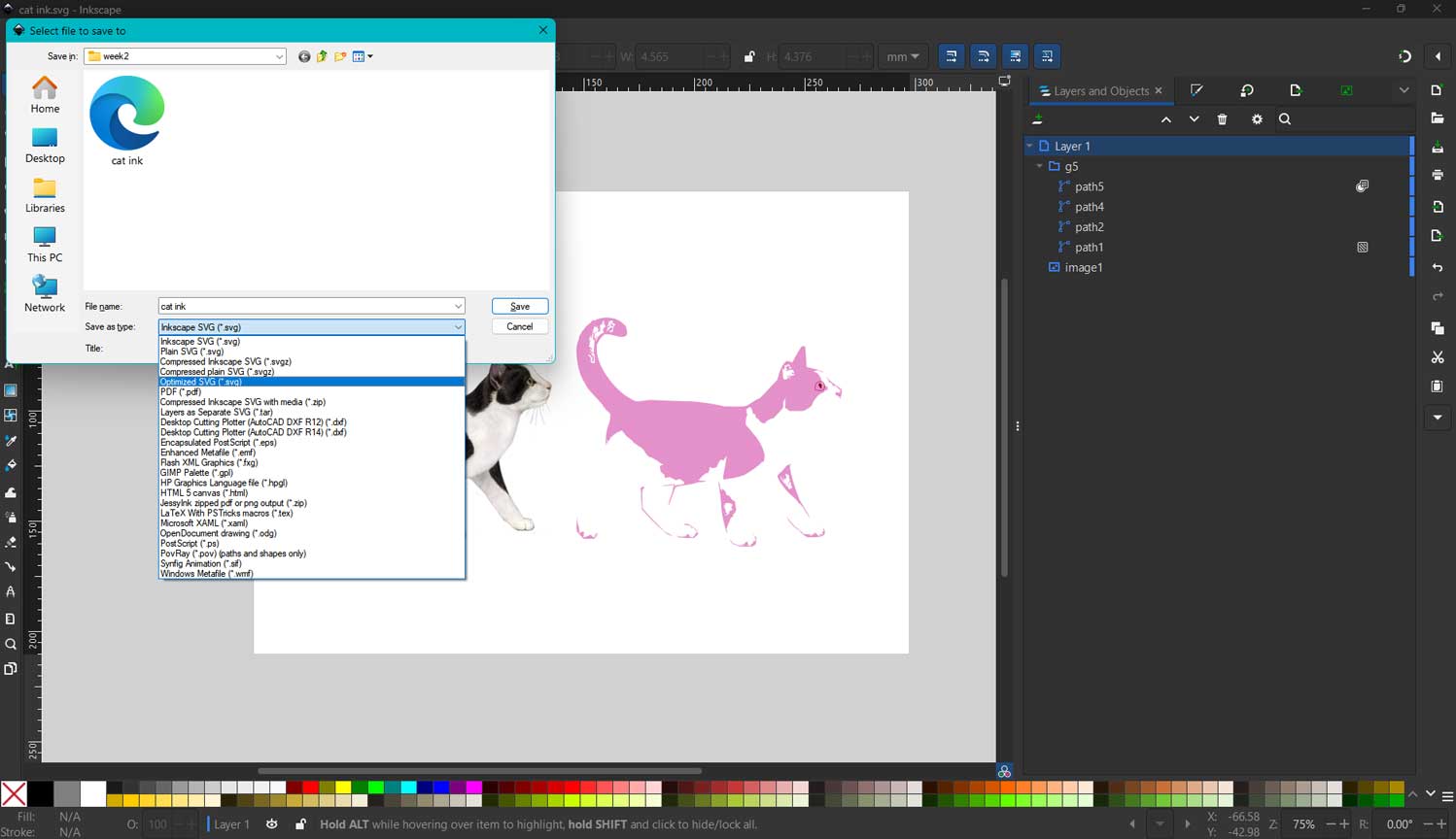
Finally, I grouped all the traced image parts into one group in the layers
panel so it would be easier to work with.
What I Learnt
Raster graphics are made of pixels and lose quality when scaled up, which makes them difficult for machines to interpret accurately. Vector graphics, on the other hand, use mathematical equations to maintain sharp and scalable lines. These lines do not break apart, and machines can understand them easily.
Why vectors matter: Laser cutters need precise lines to cut accurately, which vector graphics provide. They cannot reliably read the pixel grid of a raster image to make precise cuts.
3D software - Fusion
I have a solid background in AutoCAD, SketchUp, and Lumion, and I feel quite confident navigating those workflows.
However, Fusion 360 and Blender are still very new territory for me. I just installed Fusion in my local class this past
Thursday, and while my experience with SketchUp helps with the 3D mindset,
the interface is a completely different ballgame. The commands and the overall workspace feel totally new,
so I’m currently adjusting to how everything is laid out.
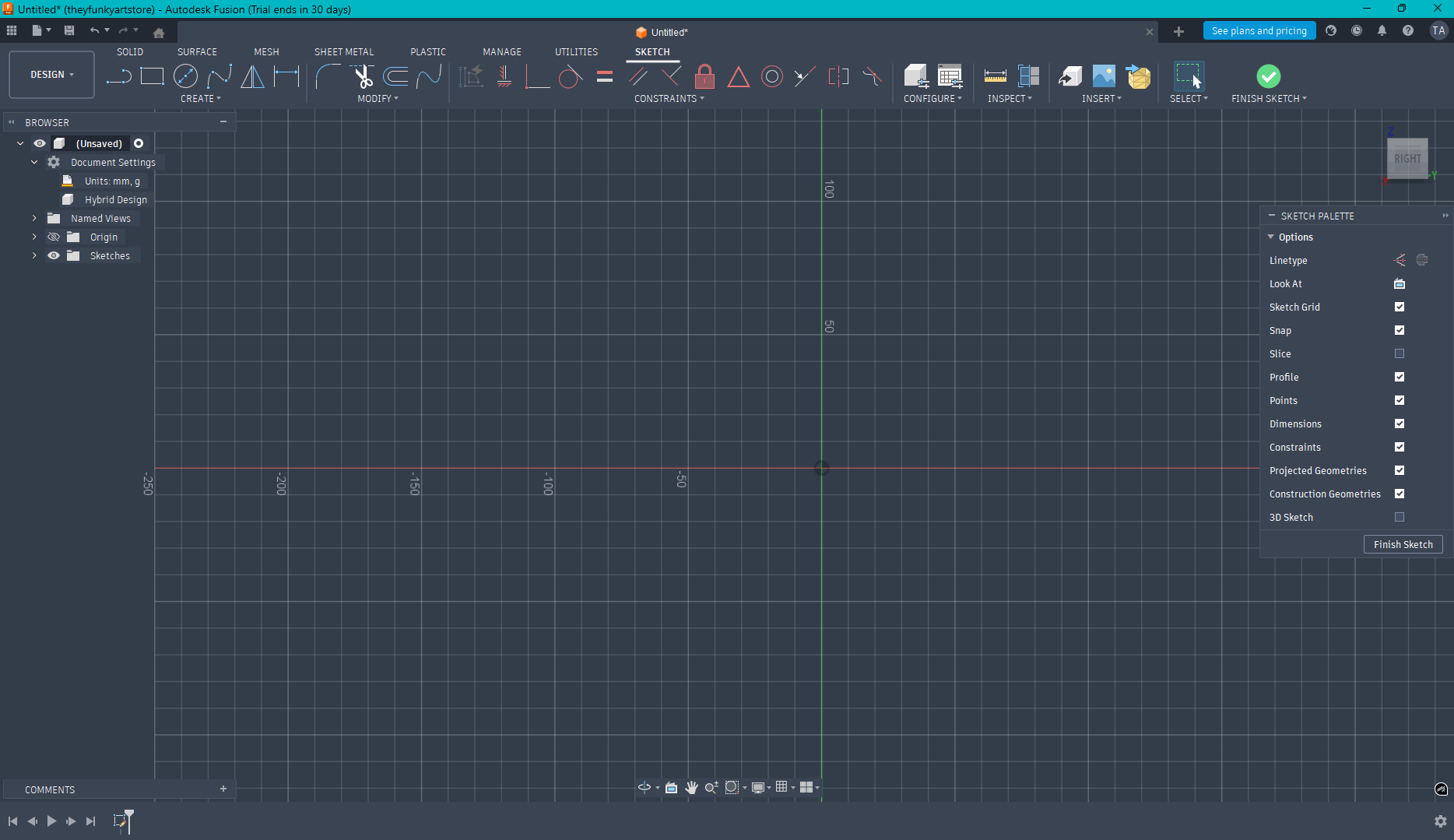
We were instructed to choose to work in the hybrid design layout .
First, click on the plane that you wish to work with.
We will be working in the Sketches workarea.
Once the profile is closed, we can use the Extrude tool to mass the body.
To start, I have to choose the plane I want to work on, so I went with the base plane.
I clicked Sketch and selected the Rectangle tool from the ribbon. To draw it, I just started the shape and
typed 500 for the first dimension; then, I hit the Tab key to switch to the other side and entered 300.
Since the initial settings were already in mm, the units were spot on from the start.
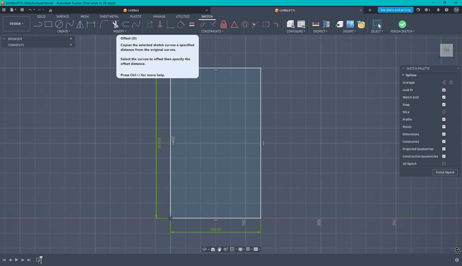
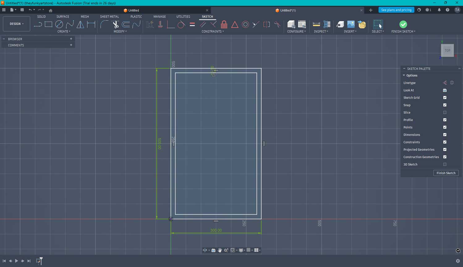
I used the Offset tool from the ribbon to create a smaller rectangle inside. I noticed that when you want to offset inward,
you have to use negative values, like -15. At first, I tried selecting the inward direction and just typing 15,
but it still offset to the outside. That's definitely something I need to be careful with in the future.
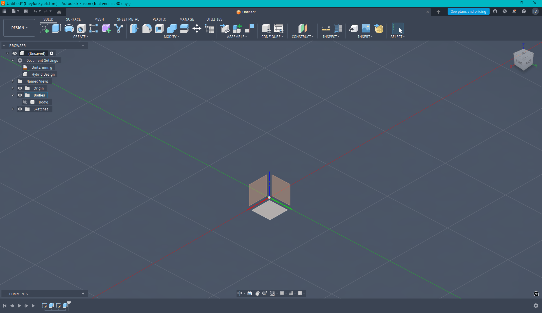
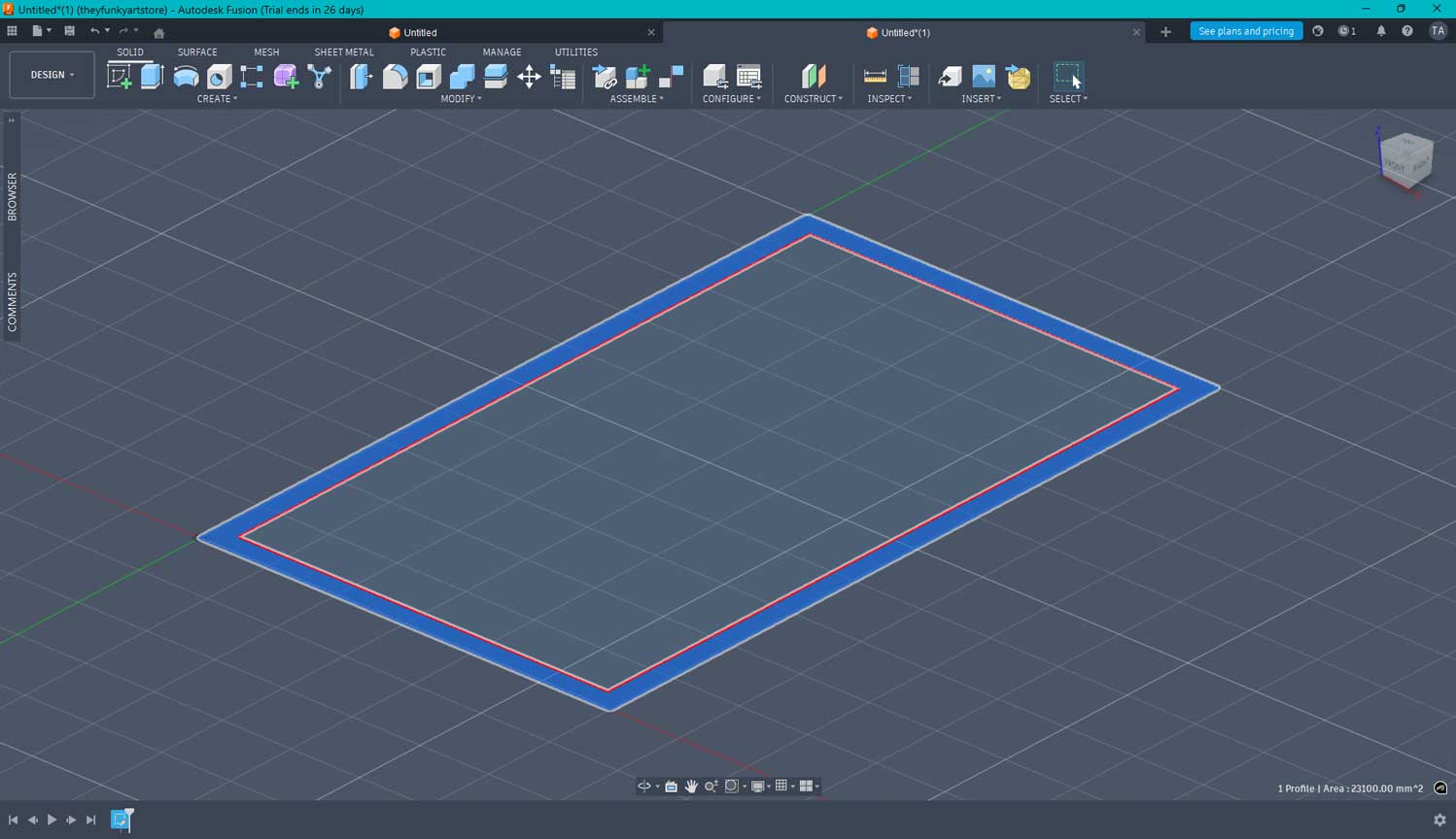
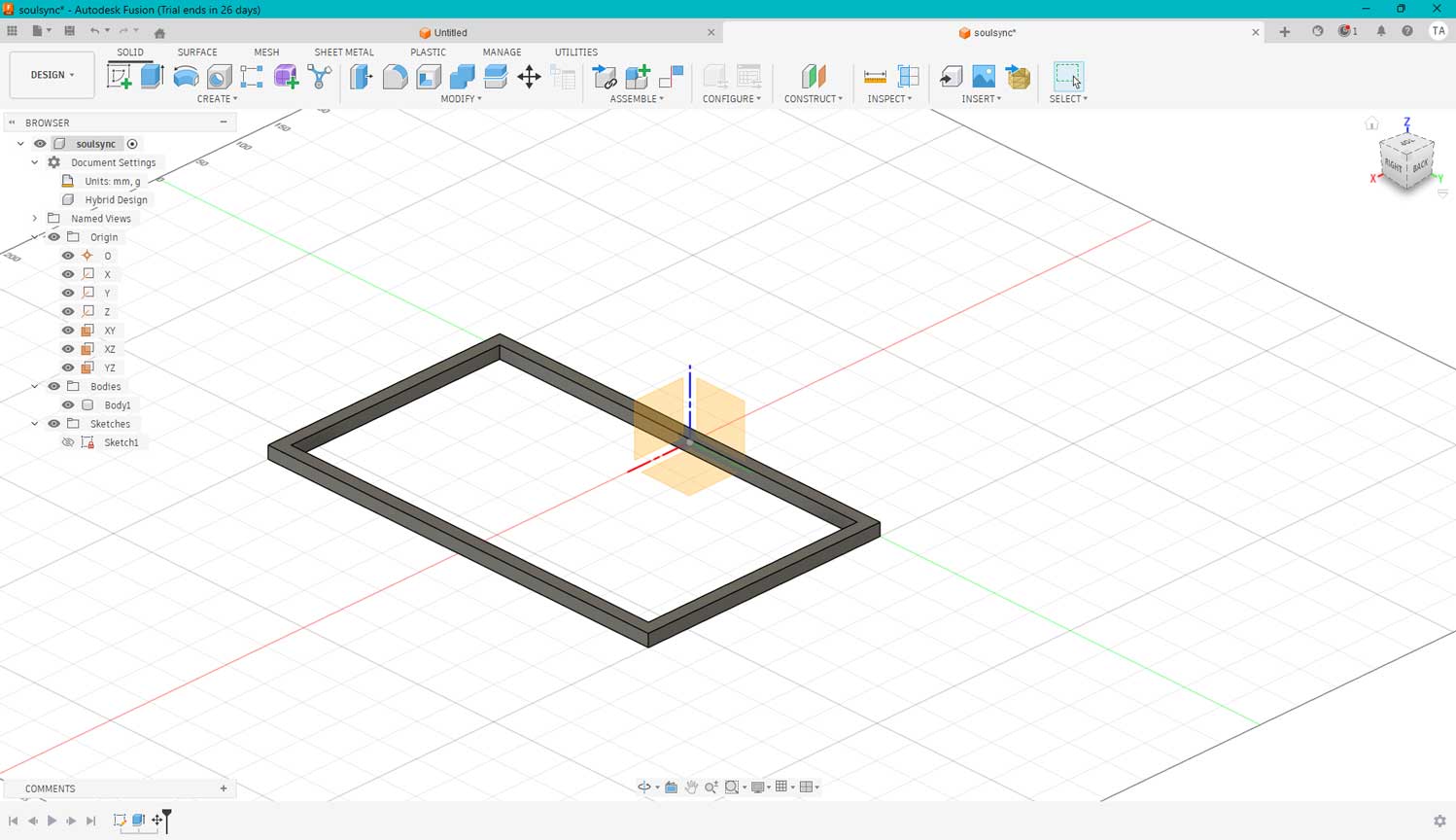
After clicking "Finish Sketch" on the ribbon, I jumped into the Extrude tool and selected the offset profile.
I typed in the dimension, and just like that, the frame was created.
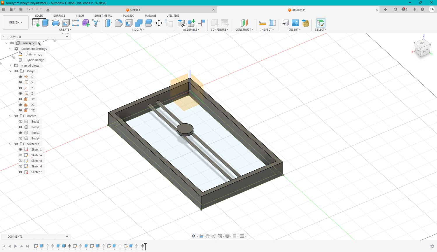
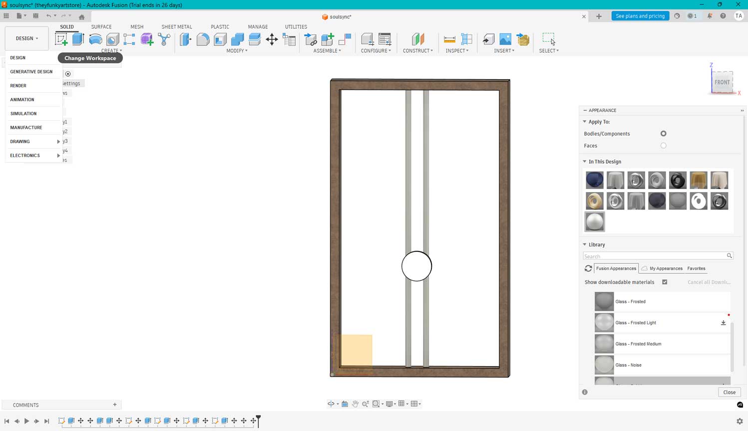
I went back into the Sketch layout to add circles onto the frame,
then switched to the Design workspace to extrude them into pipes.
To finish it off, I added a cylinder body right on top of the two pipes.
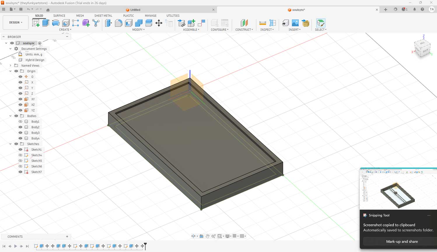
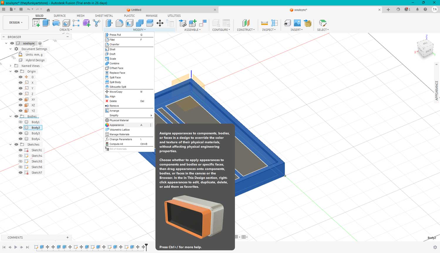
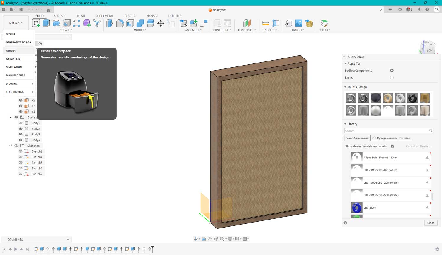
Fusion offers a Material selection feature that helps you visualize exactly how your product will look.
When you open the dialog box, a wide range of material options appears; you can simply drag and drop
them onto a body, a specific plane, or even individual faces by adjusting the settings in the box.
You can further customize these appearances by tweaking properties like reflectivity, roughness, and
translucency, allowing you to tailor the product to your exact design needs.
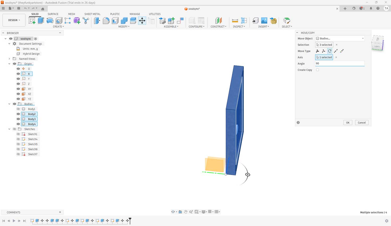
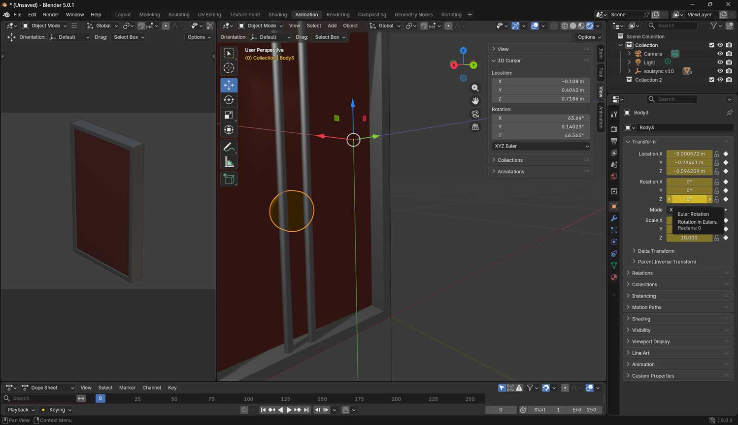
I was working on the horizontal plane, but I needed the frame to rotate along the Y-axis, so I
used the Move tool in the design workspace. I selected the rotate icon in the dialog box and typed
in the specific value to get the orientation just right.
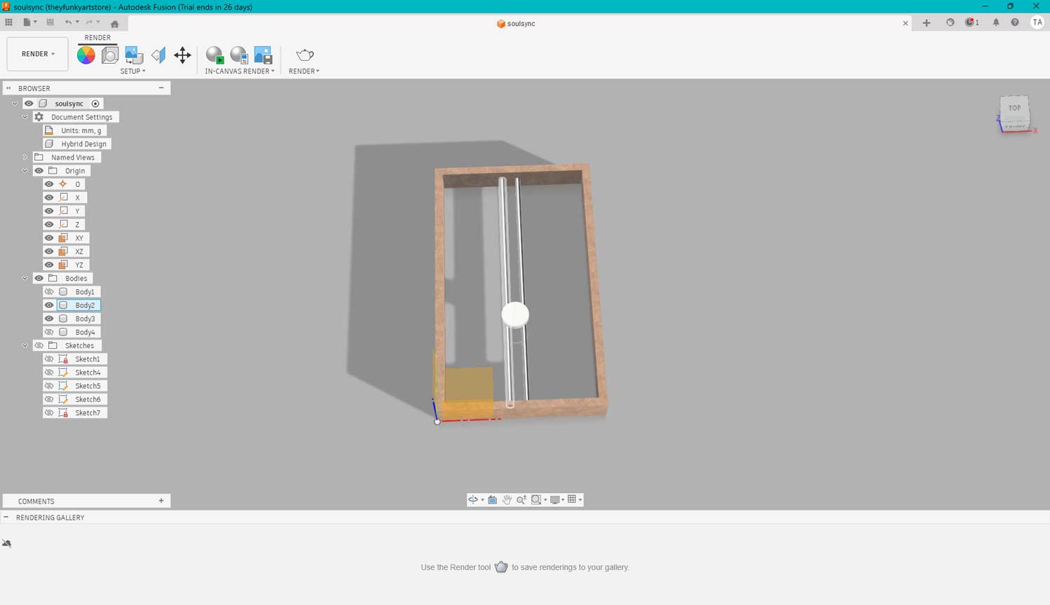
You can render your model directly within Fusion by switching to the Render workspace,
which is found in the workspace selector at the top left of the ribbon.
What I Learnt
In Fusion 360, one can define strict dimensions and constraints through parametric design. These values can be easily adjusted and updated later without having to rebuild the model from scratch. I still need to spend more time in Fusion 360 to become comfortable with it.
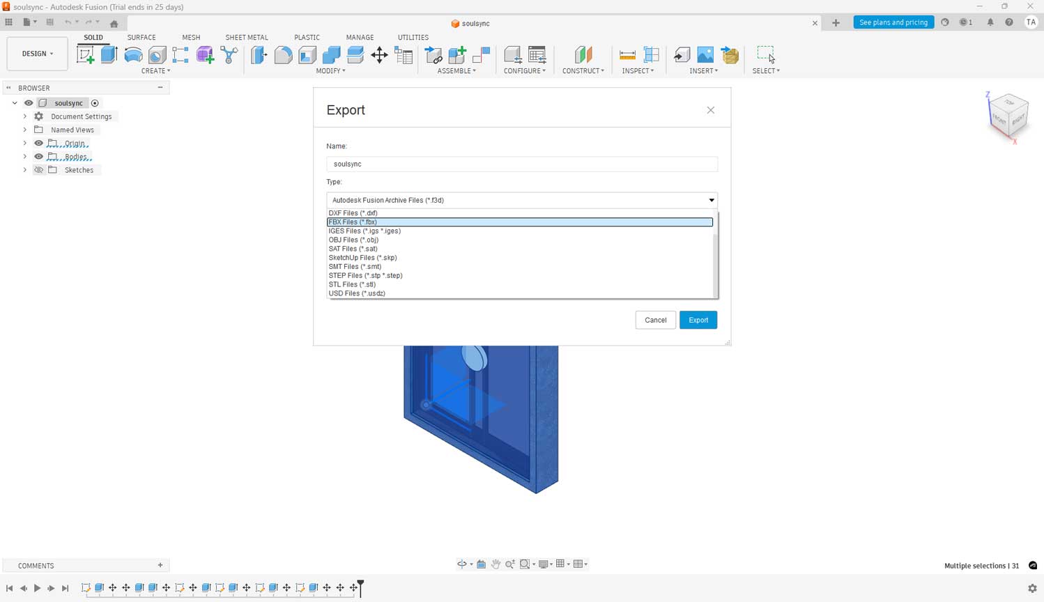
I exported the file from Fusion into Blender using the FBX format. After opening the file in Blender,
I began the animation process.
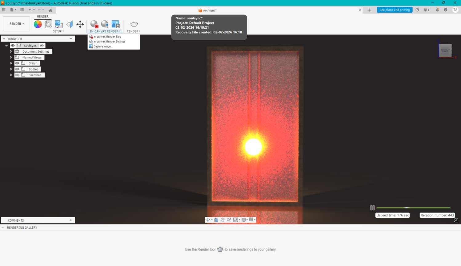
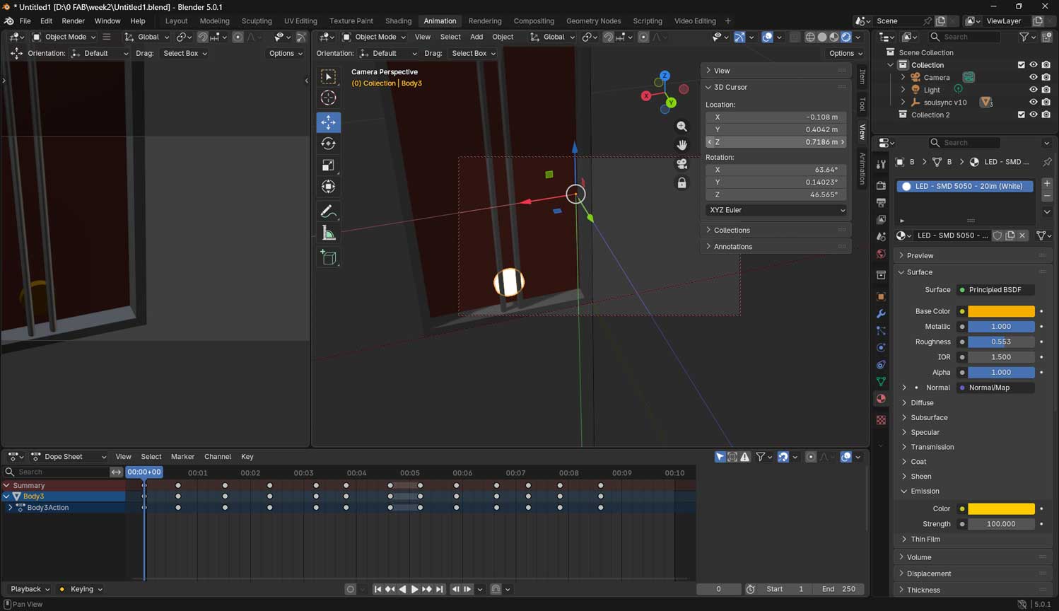
I also rendered the model by applying materials and adjusting the textures. I used the Emit setting specifically
to create a luminous, glowing effect.
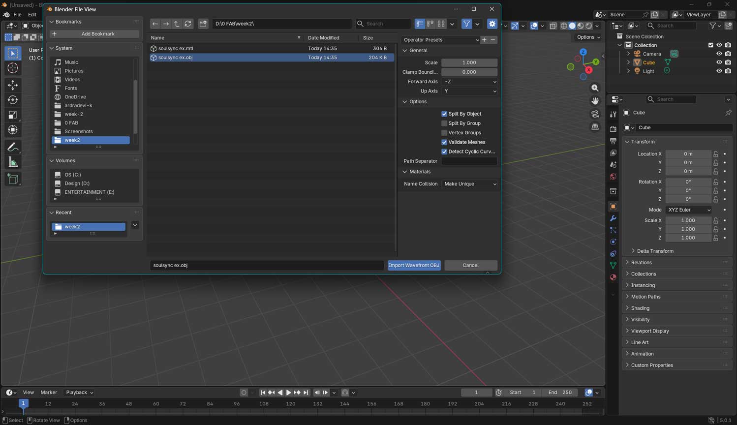
Exporting the file from blenderImporting the model to blenderAdjusting the light positionI added keyframes by changing the object's position. In this case,
I moved the light and set the keyframes by pressing the 'I' key
After setting my keyframes and completing the movement of my model, I rendered my animation into a video.
First, I went to the timeline at the bottom and set my Start Frame to 1 and my End Frame to 250 so that my
animation would run for the desired length. I then pressed the play button to check whether the movement
looked correct. Next, I went to the Render Properties (camera icon) and scrolled down to the Output section.
I clicked on the folder icon and selected a location on my computer to save my animation.
After that, I changed the File Format to FFmpeg Video. Under Encoding, I selected:
• Container: MPEG-4
• Video Codec: H.264,
so that my final output would be an MP4 file.
I then set my resolution to 1920 × 1080, which is standard HD quality, and kept my frame rate at 30 fps for
smoother motion.Finally, I went to the top menu and clicked Render → Render Animation. Blender rendered the
animation frame by frame, and my final video was saved in the folder I had chosen.
Movement of light
What I Learnt
Blender vs Fusion strengths: I should have tried a similar model in both Fusion and Blender to better understand which was easier for a particular task. Fusion is excellent for exact dimension based models, manufacturing, and parametric modelling. I would describe it as a calculated draft.
Achieving exact dimensions in Blender can be more challenging. However, Blender excels in animation, sculpting, and artistic rendering. It is more like a freehand sketch compared to Fusion's precision based approach.
Video compression
This is where we are introduced to Handbrake. It is a open-source tool, built by volunteers, for converting video
from nearly any format to a selection of modern, widely supported codecs. Most importantly it is an open source software.
After completing the Blender animation render,
I processed the 3MB file through Handbrake to reduce the footprint while maintaining visual quality.
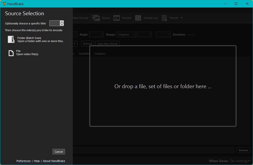
Handbrake is a software I used to compress video files. In the Handbrake window,
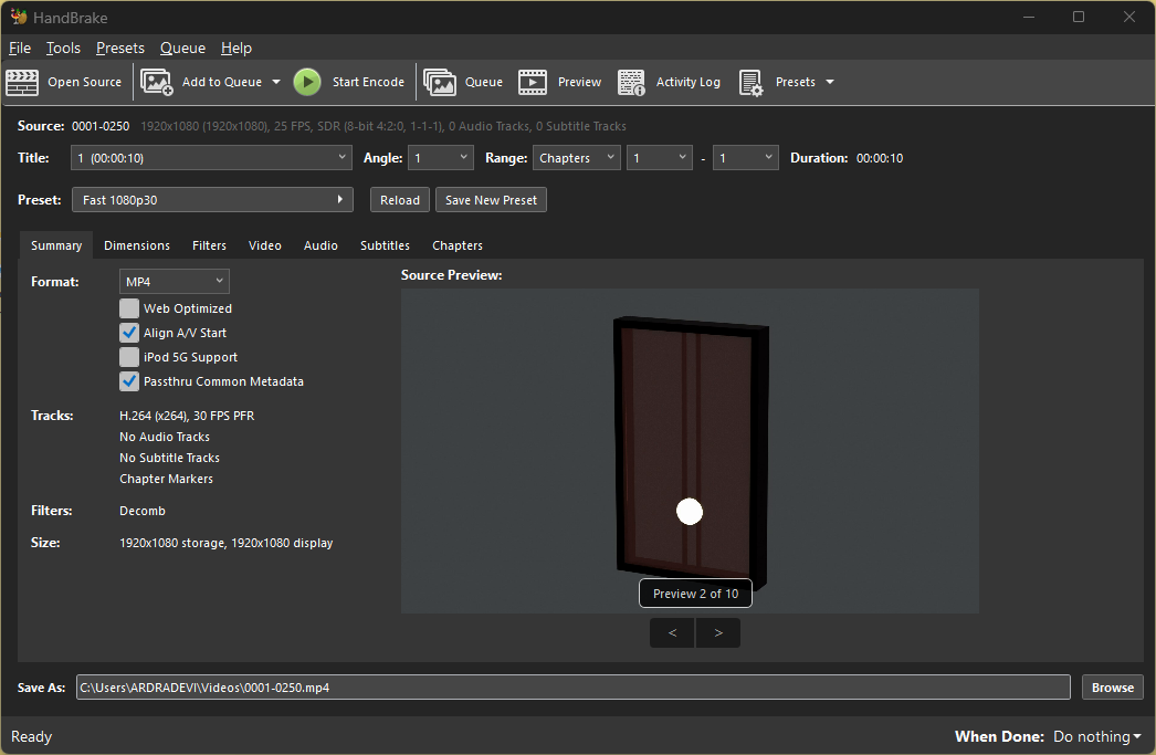
you can either drag and drop the file or choose Open Source.
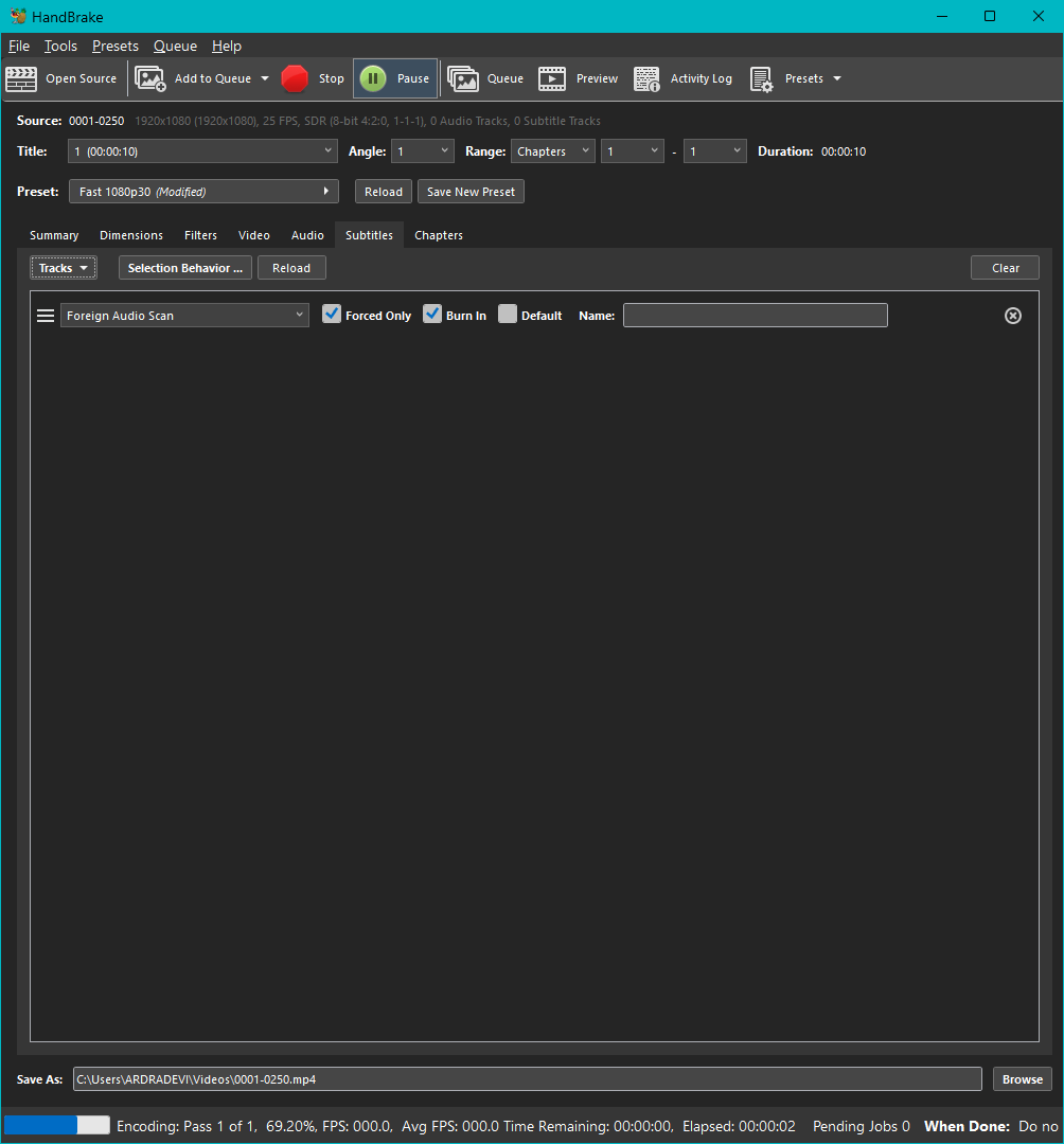
I adjusted the format and the video quality to my preference. After that, I clicked on Start Encode,
and it took a few seconds to compress the video.
Image Compression
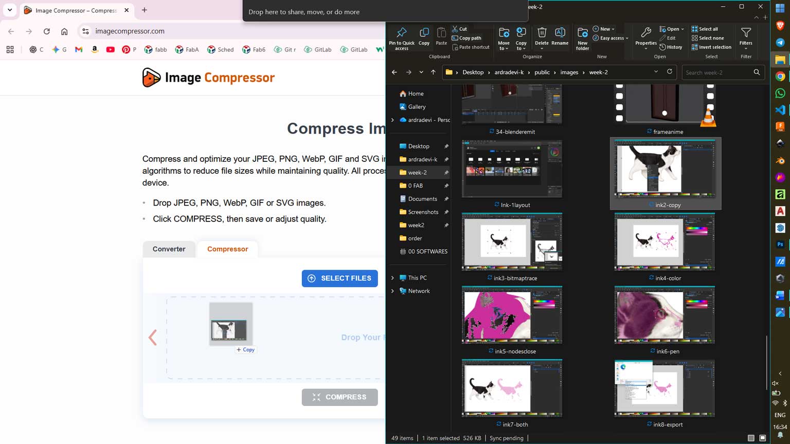
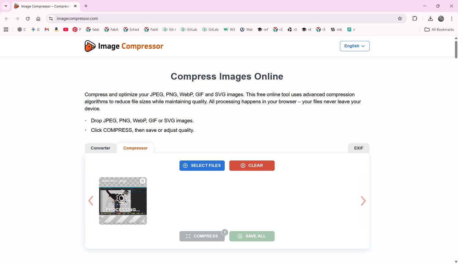
I have used a site named Image Compressor to compress the images.
This tool is very simple to use. You just drag and drop the file onto the website you can even upload multiple images at once.
After that, click “Compress,” and the site processes the image to a smaller file size. You can then download and
save these compressed files back into your folder.