WEEK 16
System Integration
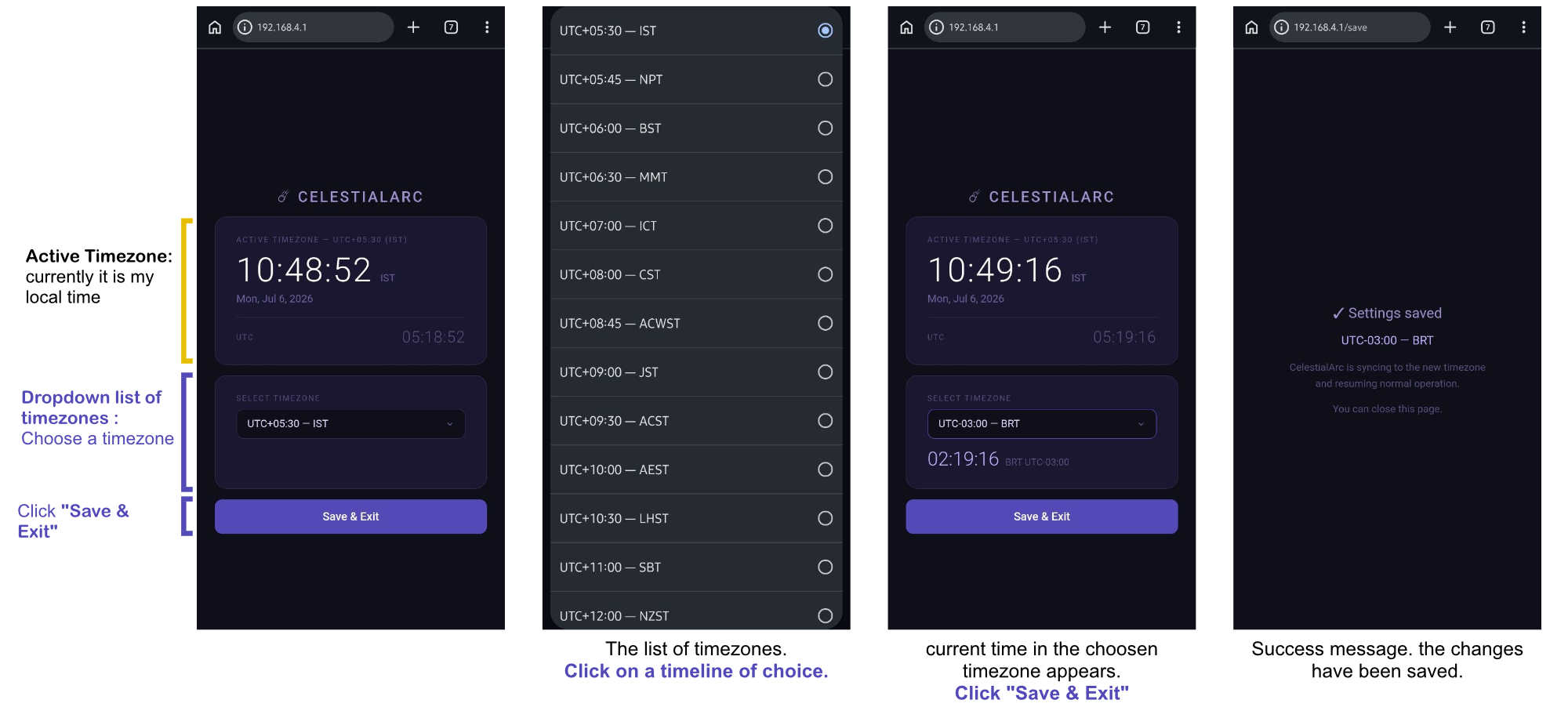
How the week started
The assignment ends in one sentence but the task of completeing it is making me doubt if one week will be enough!! Not to forget documenting it. At this rate I feel there should be an additional day in the week to compelete Documentation
How the week ended
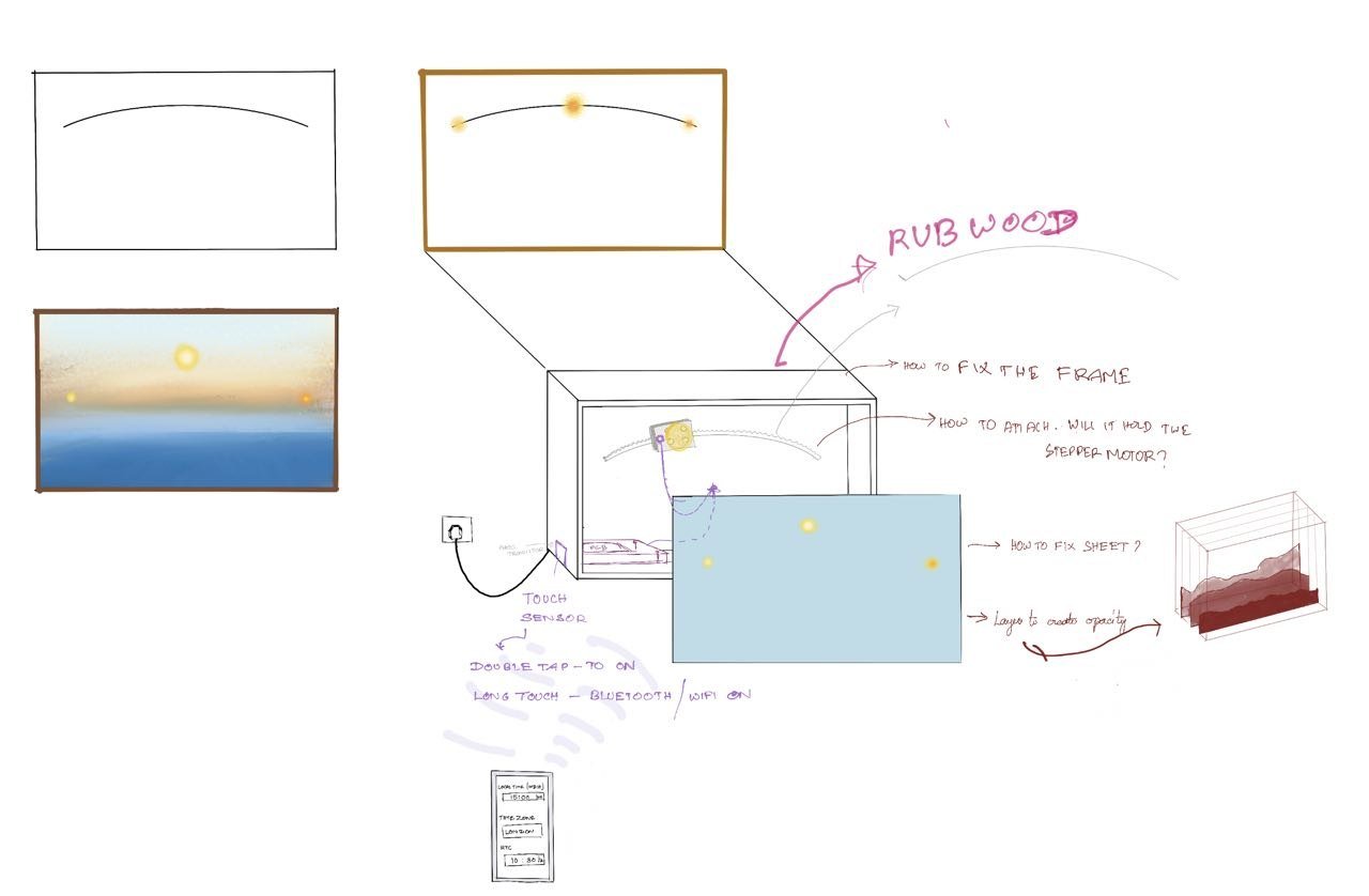
A lot of insight was gained into my own project. Questions that I had not considered were raised, and I had to find answers to some of them. My idea was to have the layered image in the front, but this led to the question of how exactly it would be placed. I also had to consider how this could be done without the paper warping after it was attached.
Week 16’s Assignment
- Design and document the system integration for your final project.
INSPIRATION
My final project is inspired by these mechanical picture frames with an illuminated sun that can be moved along an axis. I thought about automating this, but then I questioned why I would need it as a clock when I already have clocks around me. This led to the idea of using it to show the time of a friend living abroad. If the sun could move on its own based on time, it would become a visually appealing way of displaying it.
System Integration Through Motion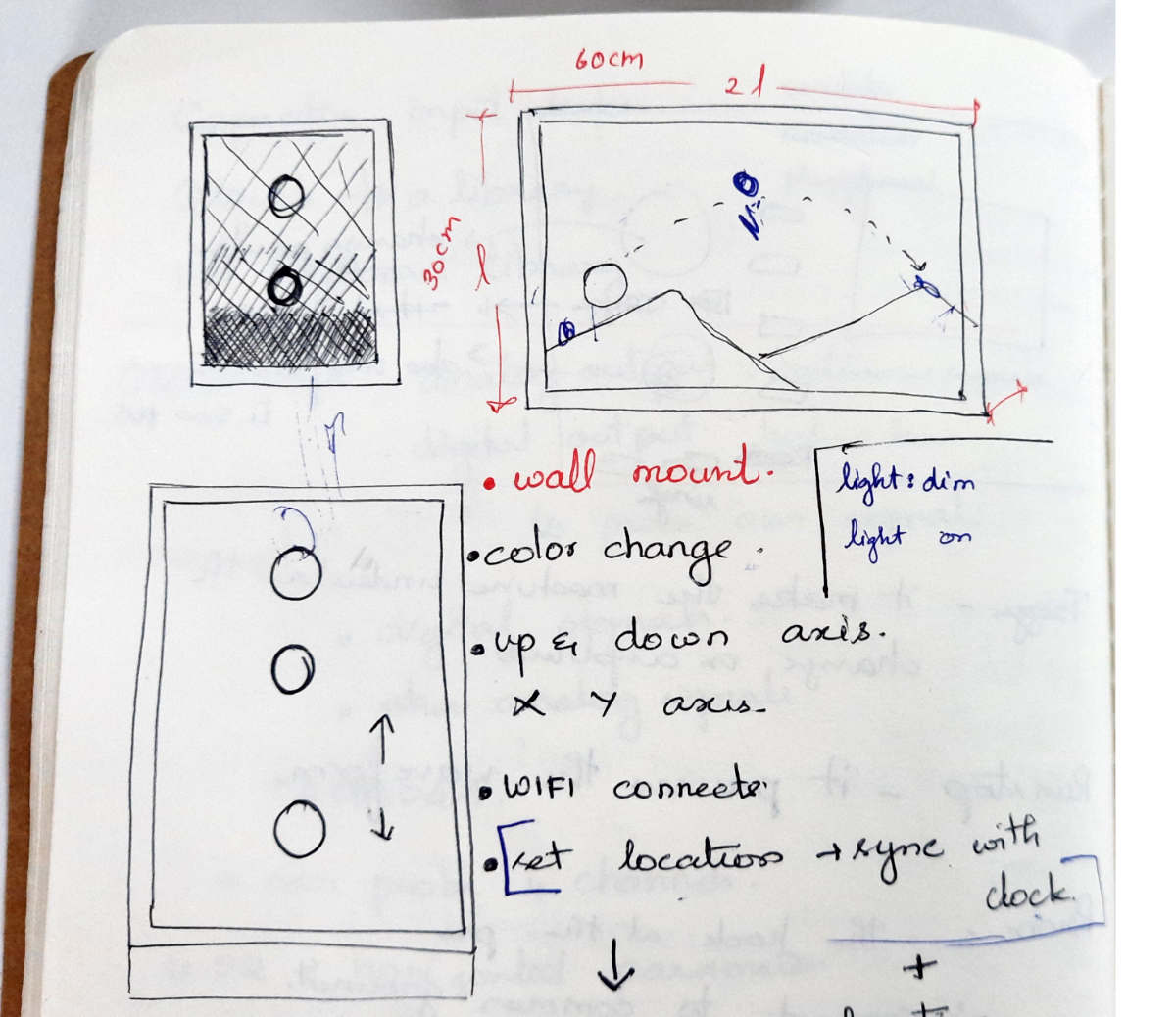
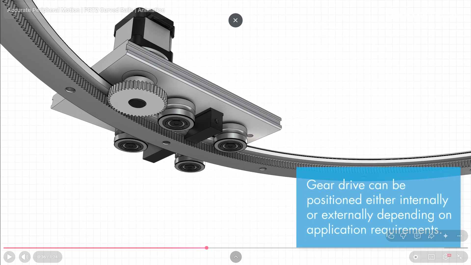
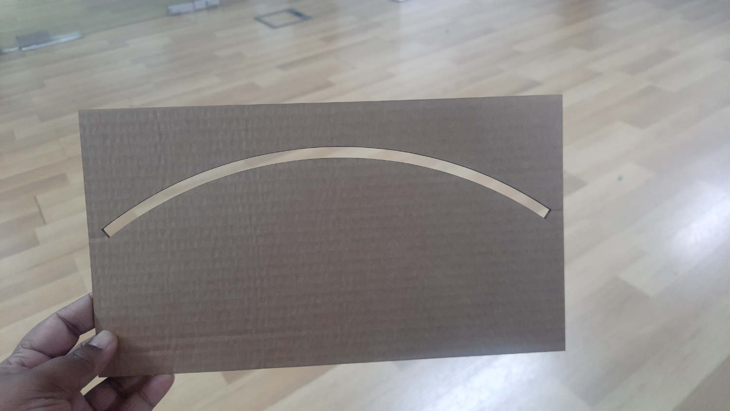
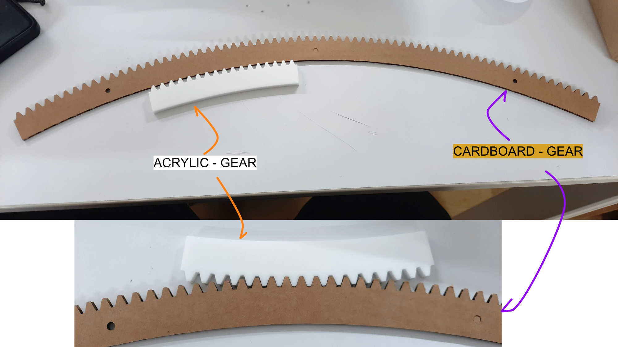
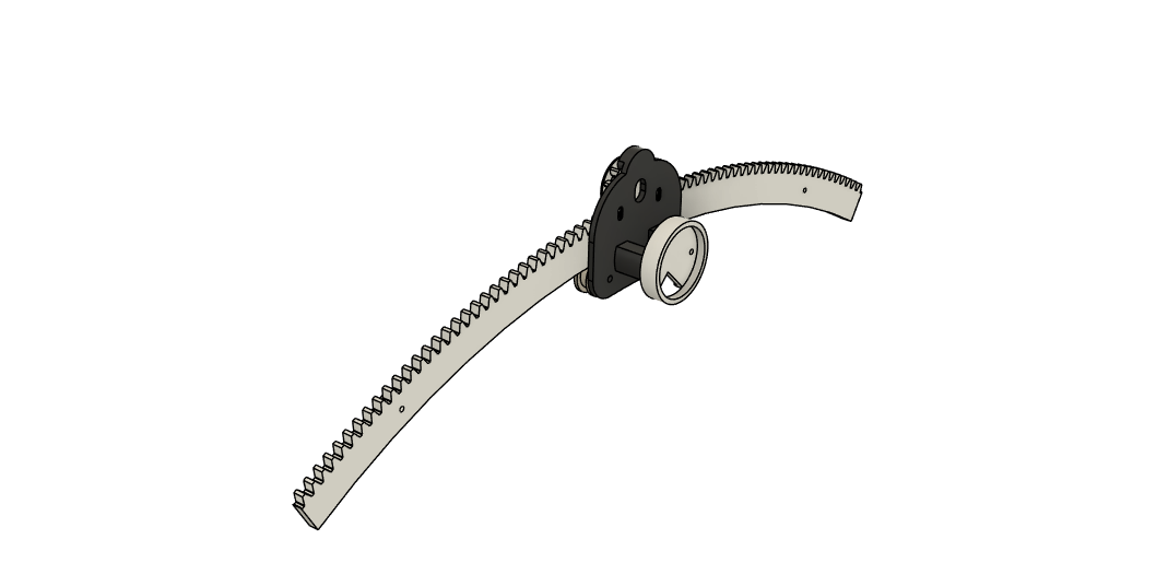
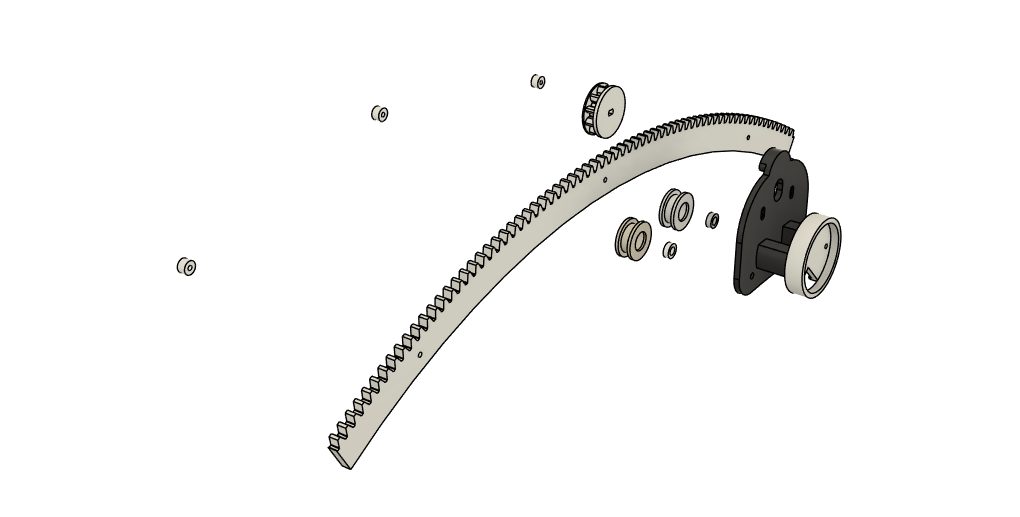
The first question that came up during the discussion was how the sun would move. Would it move up and down, horizontally, or in another way? Initially, I chose a simple up and down movement. Later, it dawned on me that the sun path diagrams used in architectural drawings closely resemble the actual movement of the sun that we observe in the sky. Because of this, I wanted the sun to move in an arc.
The arc would represent the journey of the sun, starting from one point on the left and gradually moving toward the right as time passes. This angular motion could visually communicate the passage of time in a more intuitive and engaging way. Later, the idea evolved further, where the sun could return to its starting position and transform into a moon, creating a continuous day and night cycle.
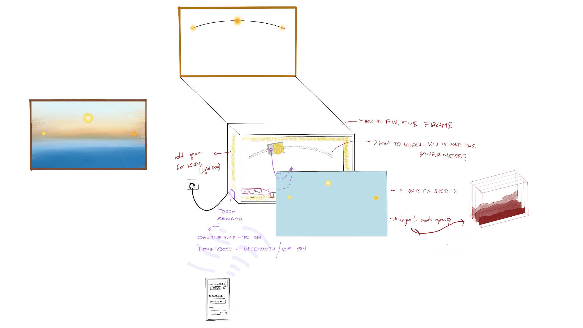
Drawn on procreate to understand system integration
Scale
How small or large was the model going to be? Initially, I wanted it to be 100 cm by 60 cm. During the discussion with Sibin, we measured the table and marked the size that would be pleasing. The fixed size was based on a monitor's dimensions, around 60 cm x 35 cm, literally half of the inital size.
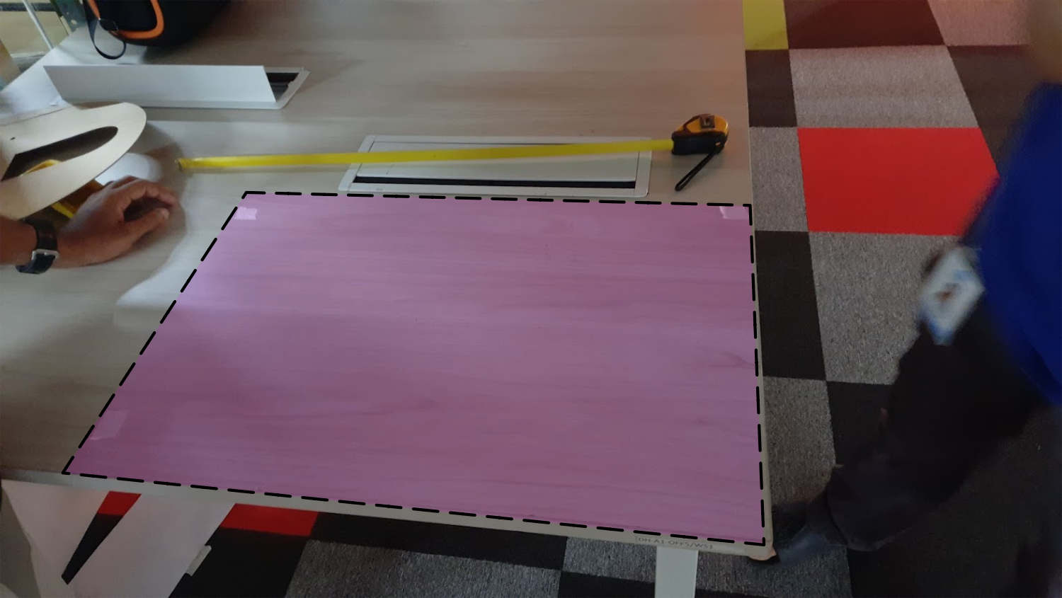
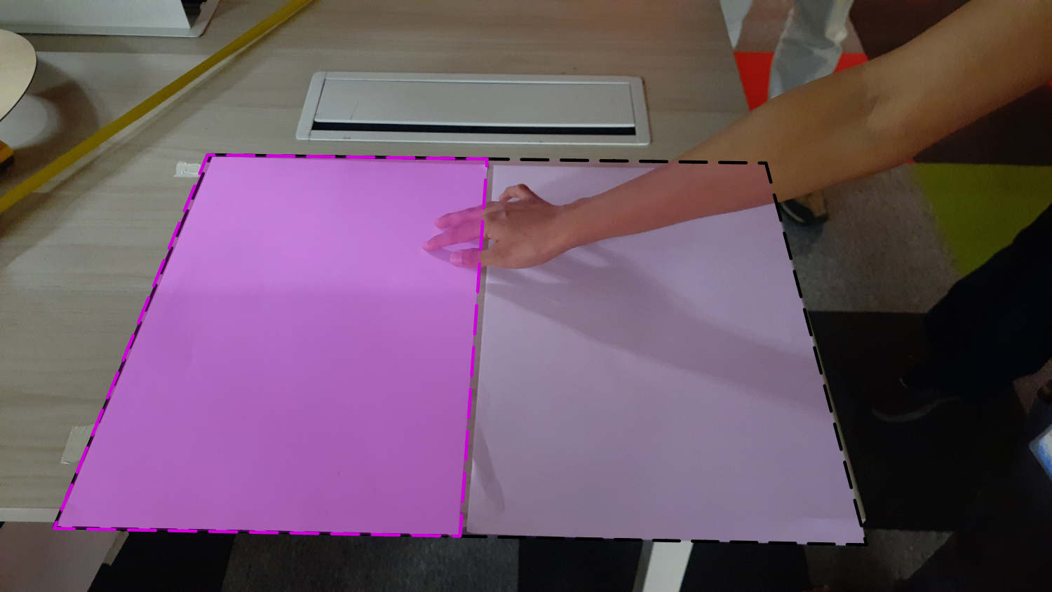
100cm * 60m that was first considered by me
After discussion it cam edown to 60cm * 35cm . The dark pink shade is the choosen size.
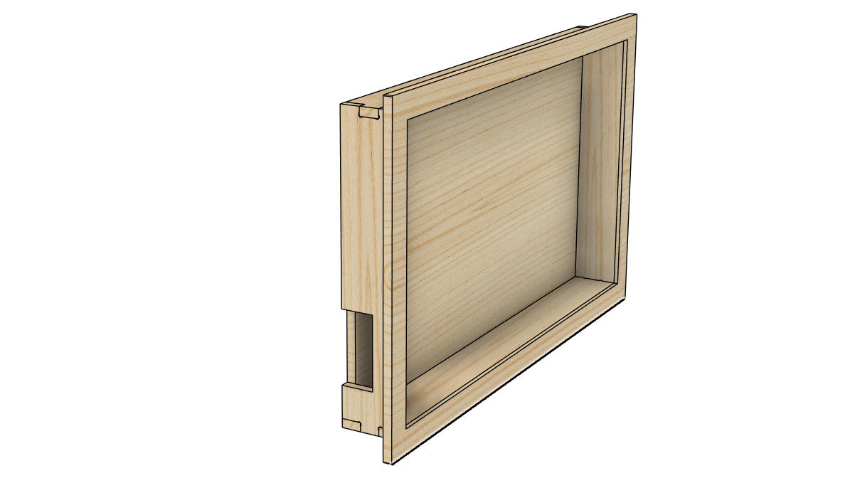
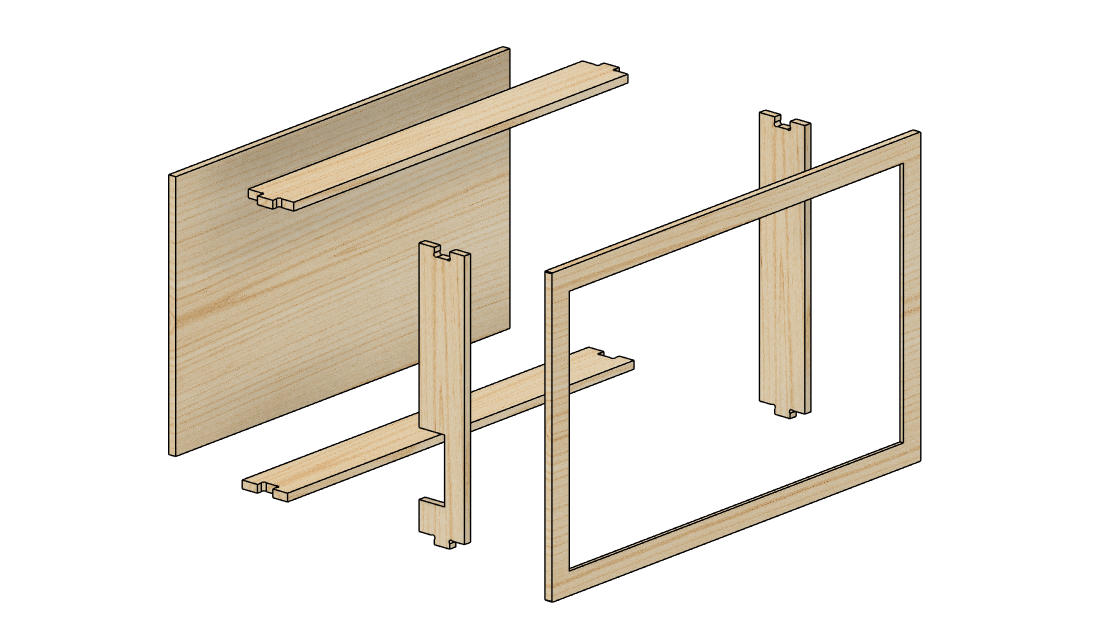
The wooden frame structure
Rubwood is routed as panels with finger joints
Layered image

I chose colors similar to the sun's colors. I bought synthetic paper from a local store. This paper would withstand wear and tear and provided good diffusion.
The layers were cut by hand and arranged to mimic a minimal scenary
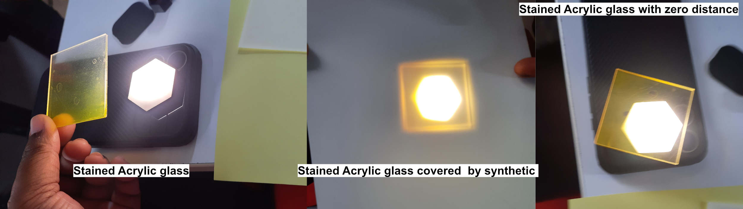
Tested the visibility of the light through layers of paper to know how it affects the output and what distance was feasible.
Electronic System
Choosing the developer baord
Choosing a developer board is important. It depends on the components chosen and whether the developer board has enough pins to accommodate all the components. ESP32-WROOM32 was the first board chosen. After checking whether the SEEED XIAO ESP32C6 had enough pins to handle all the components, it was also chosen because of the Type C connection it has, which could be directly used to charge the unit.
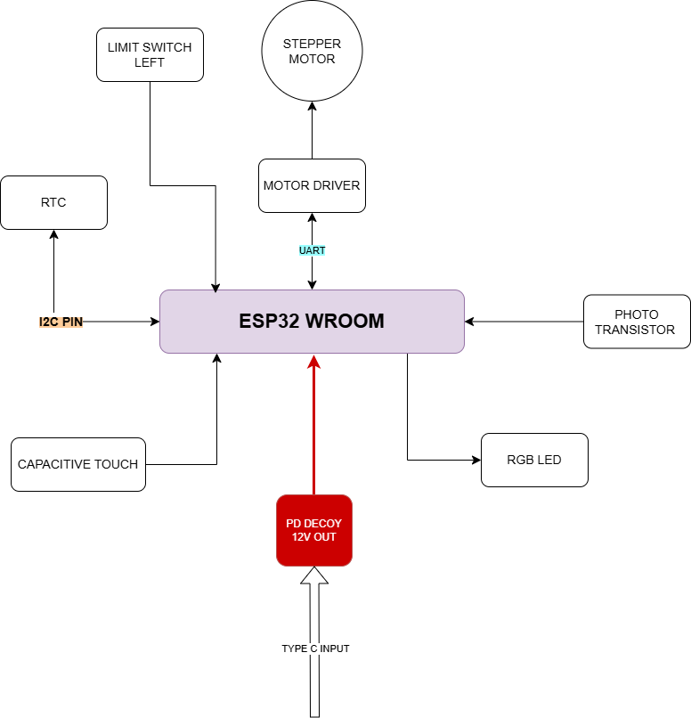
The initial components chosen with the ESP32-WROOM32.
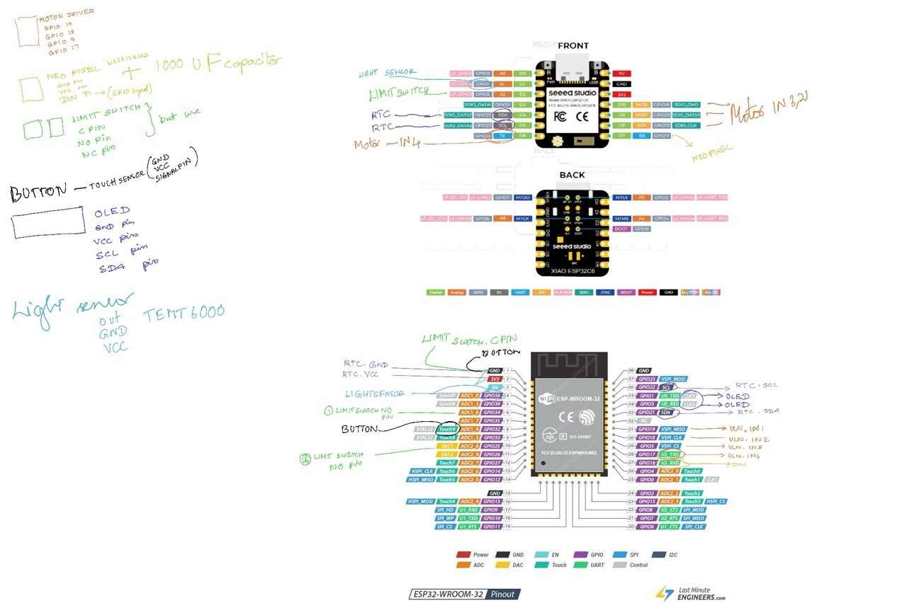
Pinout connections made.
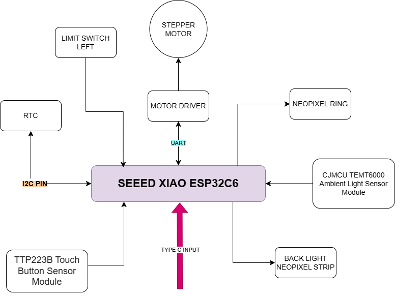
The board setup after choosing the SEEED XIAO ESP32C6.
Bill of Materials - Electronic Components
| Sl. No | Category | Item | Quantity | Unit Cost (₹) | Total Cost (₹) | Supplier | Alternate Supplier | Search Name |
|---|---|---|---|---|---|---|---|---|
| 1 | Microcontroller | XIAO ESP32-C6 | 1 | 555 | 555 | FAB INVENTORY | Link | Seeed Studio XIAO ESP32C6 |
| 2 | Stepper Motor | 28BYJ-48 Stepper Motor 5V | 1 | 92 | 92 | FAB INVENTORY | Link | 28BYJ-48 Stepper Motor DC 5V |
| 3 | Motor Driver | ULN2003A IC | 1 | 75 | 75 | ROBU | Link | ULN2003LVDR Texas Instruments Darlington Array |
| 4 | NeoPixel | WS2812B RGB SMD 5050 LED | 9 | 5 | 45 | FAB INVENTORY | Link | WS2812B RGB SMD 5050 LED |
| 6 | RTC | DS3231 RTC Module | 1 | 158 | 158 | ROBU | Link | DS3231 AT24C32 High Precision Clock I2C Module |
| 7 | Limit Switch | Limit Switch | 1 | 49 | 49 | FAB INVENTORY | Link | OMRON 3D Printer Limit Switch ENDSTOP SS-5GL |
| 8 | Light Sensor | CJMCU TEMT6000 Ambient Light Sensor Module | 1 | 80 | 80 | ROBU | Link | CJMCU TEMT6000 Ambient Light Sensor Module |
| 9 | Battery for RTC | CR2032 Coin Cell Battery | 1 | 43 | 43 | ROBU | Link | Panasonic CR2032 3V Lithium Coin Battery |
| 10 | NeoPixel Strip | WS2812B LED Strip 60 LED/M | 1 | 720 | 720 | Quartz Components | Link | WS2812B Neopixel LED Strip 60LED/MTR |
| 11 | Touch Module | TTP223 Touch Key Module | 1 | 14 | 14 | ROBU | Link | TTP223 Touch Key Module |
The bill of materials consists of key electronic components required for the project, including the XIAO ESP32 C6 microcontroller, stepper motor and driver, RTC module, sensors, NeoPixels, and supporting modules. Most components were sourced from FAB Inventory and Robu, with the NeoPixel strip being the single most expensive item. Total estimated cost: ₹1,831
This process raised the question of where the touch pad would be placed. Until now, a bare touch pad had been used, so how could this be added to the model? How would the wires be connected? What type of power supply would be needed? Would Type C be enough, or would it need a power jack? Where would this be placed? How would the wire to the motor be handled?
Components position & Connectors :
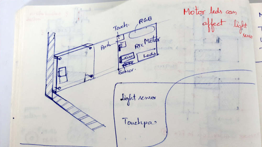
Did a rough sketch to plan the placement of the components on the board
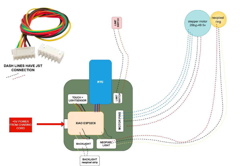
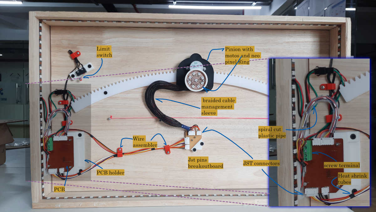
The see the wire connections and understood that most of the wired connections need JST Through-Hole 90-degree connector JST-XH (2.54mm pitch) . The wires have to be held at a point. In the motor and NeoPixel connection, that is very important. As the model has moving parts the wires could hinder the motion. JST XH 2.54mm Female Both End Pre Crimped Contacting Wire 22AWG Black – 300mm these wires were used, precrimped so the process was easier when connecting to JST
PCB 3D views and Incoporeation into design
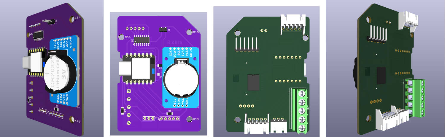
Views of the PCB. Need to keep in mind the JST pins space and wires
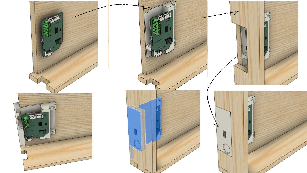
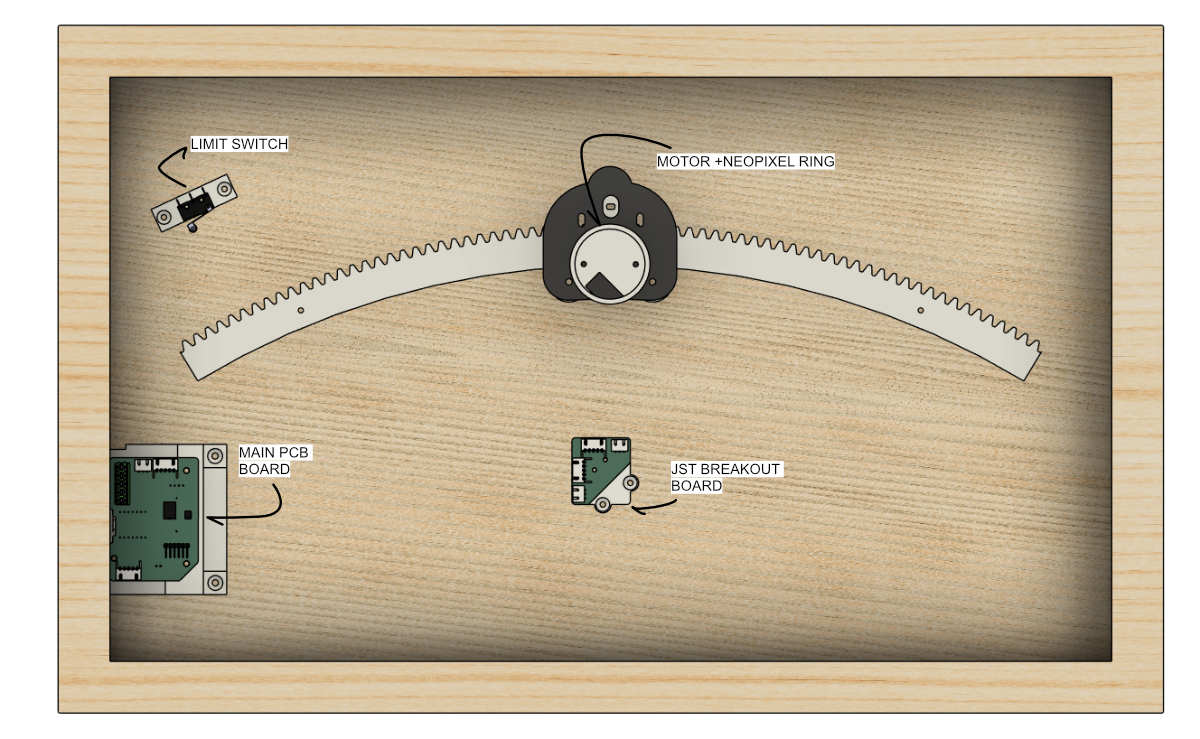
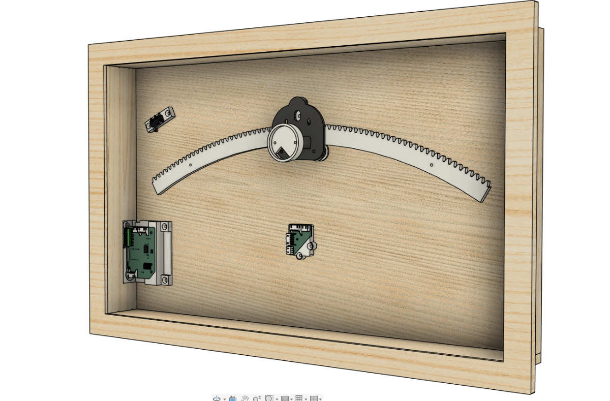
In the model this was how it was integrated
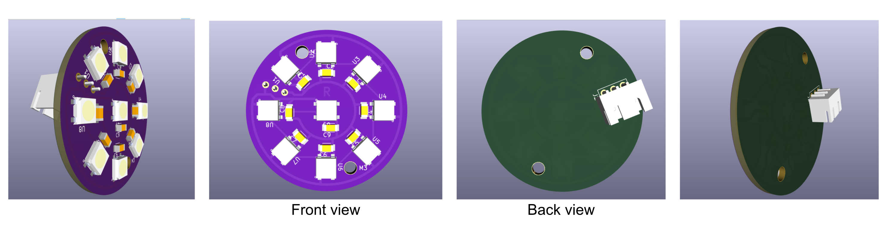
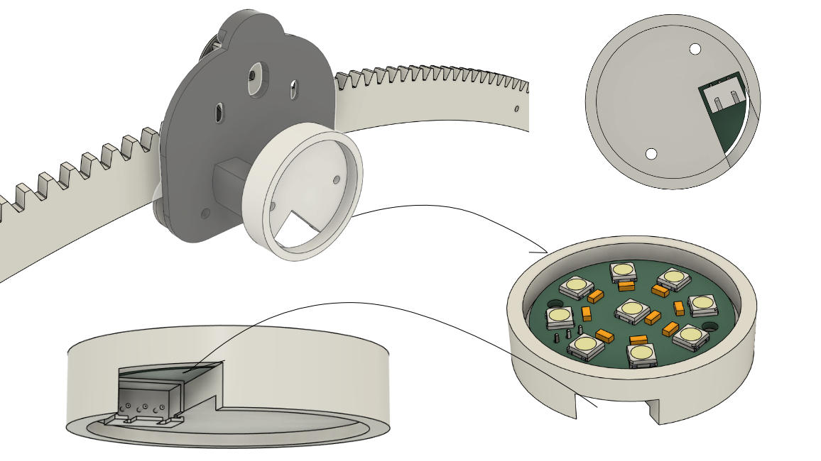
The JST pin was placed on the back and the pins soldered on the front side of the PCB. I kept note of this and added it to the neopixel ring holder. Importing the model helped to design the holder with space for JST pin and wires to pass through.