Week 12: Mechanical Design & Machine Design
Kanji-XYZ, a CoreXYZ plotter for Kanji
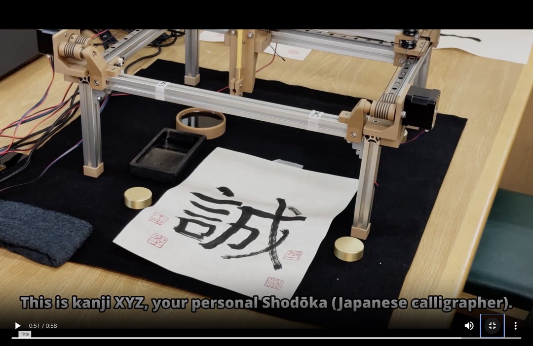
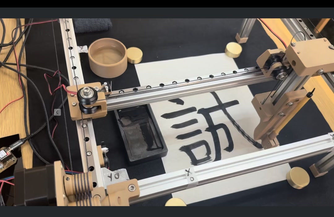 Drawing kanji with a z-axis brush stroke
Our team (Kieran, Youssef and me) built Kanji-XYZ, a CoreXYZ platform plotter that writes Japanese calligraphy with an actual brush. The Z-axis lifts and lowers the brush so that pressure changes produce the thick/thin strokes characteristic of Japanese calligraphy.
Group page: Fab Lab Kannai – Machine Building 2026
Assignments
Mechanical Design – Group Assignment
- Design a machine that includes mechanism + actuation + automation + application
- Build the mechanical parts and operate it manually
- Document the group project
Mechanical Design – Individual Assignment
- Document your individual contribution
Machine Design – Group Assignment
- Actuate and automate your machine
- Document the group project
Machine Design – Individual Assignment
- Document your individual contribution
How the team planned and allocated tasks
Our instructor Tamiya-san had already prepared the overall mechanical architecture — the CoreXYZ frame, belts, kinematics, and sample code — as part of the Machine Building Prep . Starting from that baseline, the three of us split the remaining build work along each person’s strengths:
- Youssef – Z-axis gantry caps and motor mounts, wood-PLA filament profile, thin-brush adapter
- Kieran – brush clamp in flexible PLA, firmware, KanjiVG stroke extraction and Flask frontend
- Fumiko (me) – three stepper-driver PCBs, decorative feet / spacers, limit-switch mounts, and the water dish
Our shared goal was to have a machine that could draw a full kanji on paper by Friday. Details of the full schedule and BOM are on the group page.
My individual contribution
1. Three stepper-driver PCBs with national-flag artwork
The machine needs three identical stepper-driver boards (one each for X, Y and Z). Rather than milling three visually identical boards, I took the PCB layout from the Machine Building Prep page as a PNG and dropped a national-flag graphic into an empty area of the silk region for each teammate’s board.
| Board | Flag | Preview |
|---|---|---|
| Kieran (Canada) | 🇨🇦 | 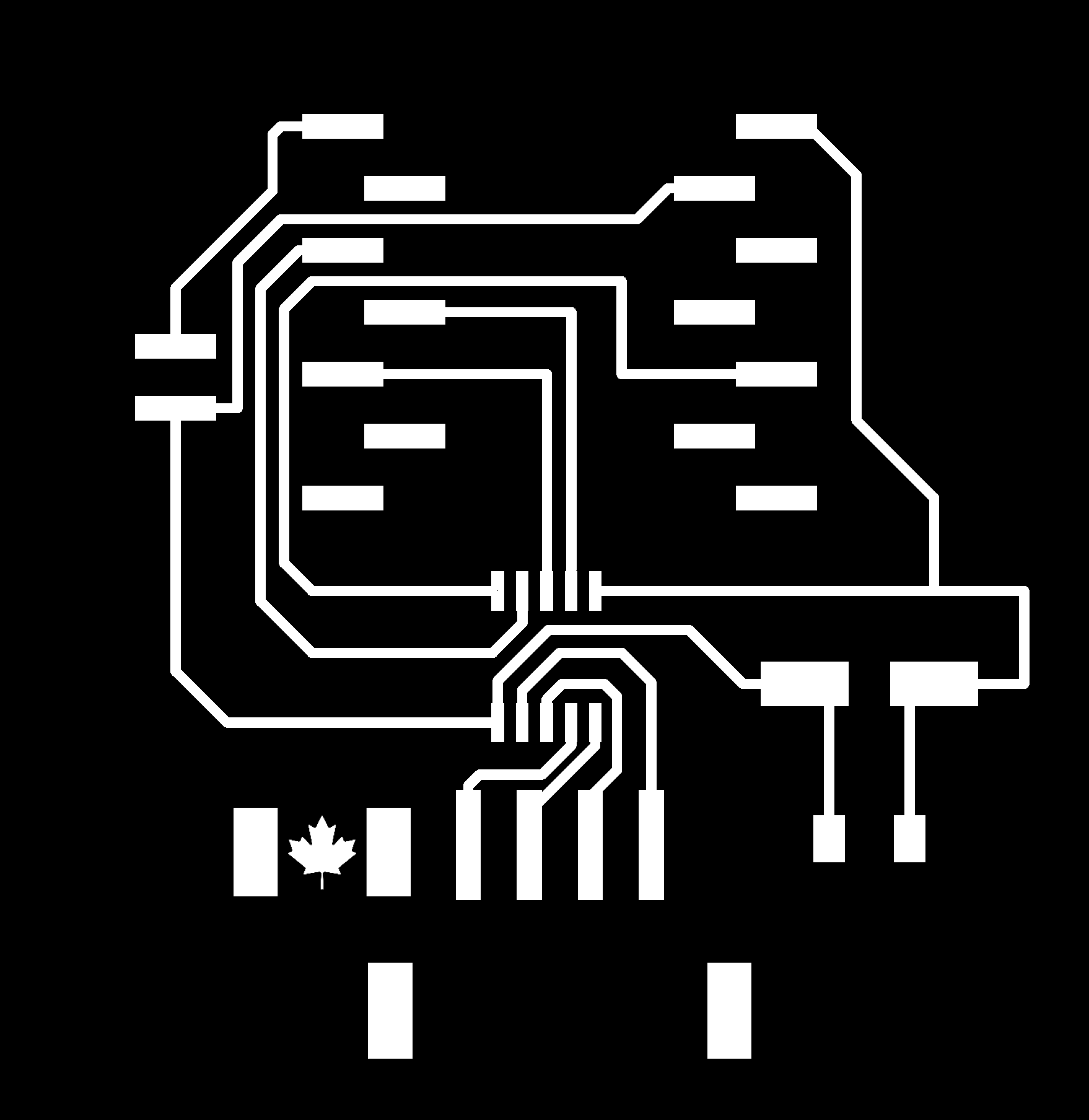 |
| Youssef (Syria) | 🇸🇾 | 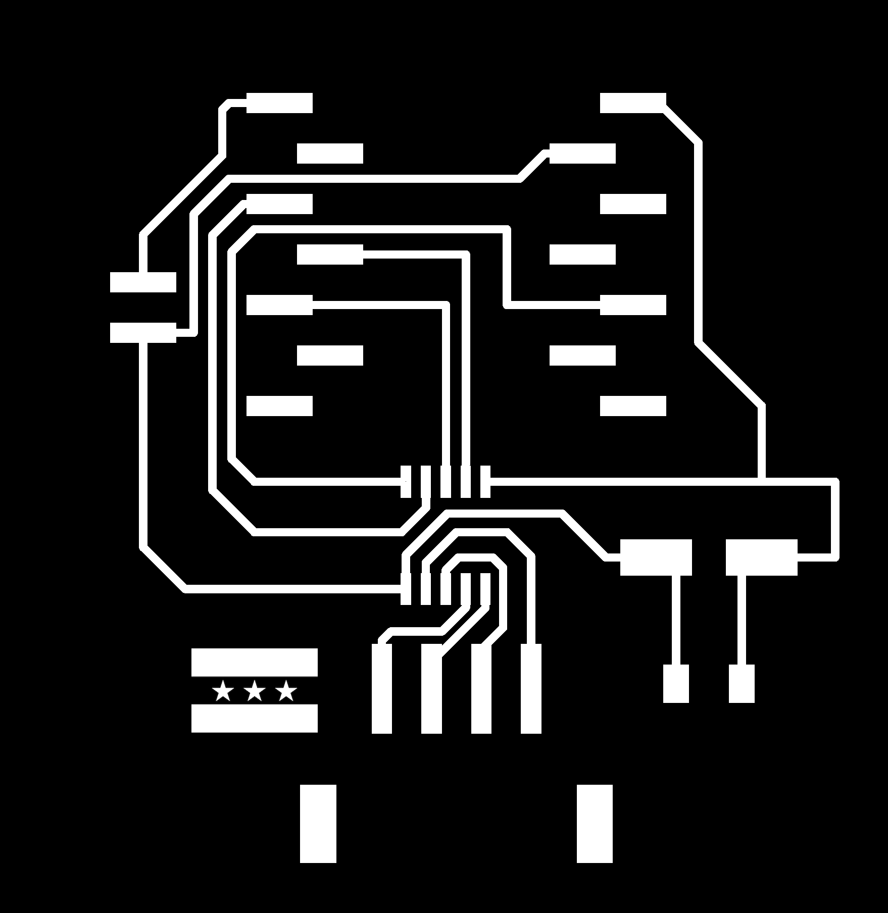 |
| Fumiko (Japan) | 🇯🇵 | 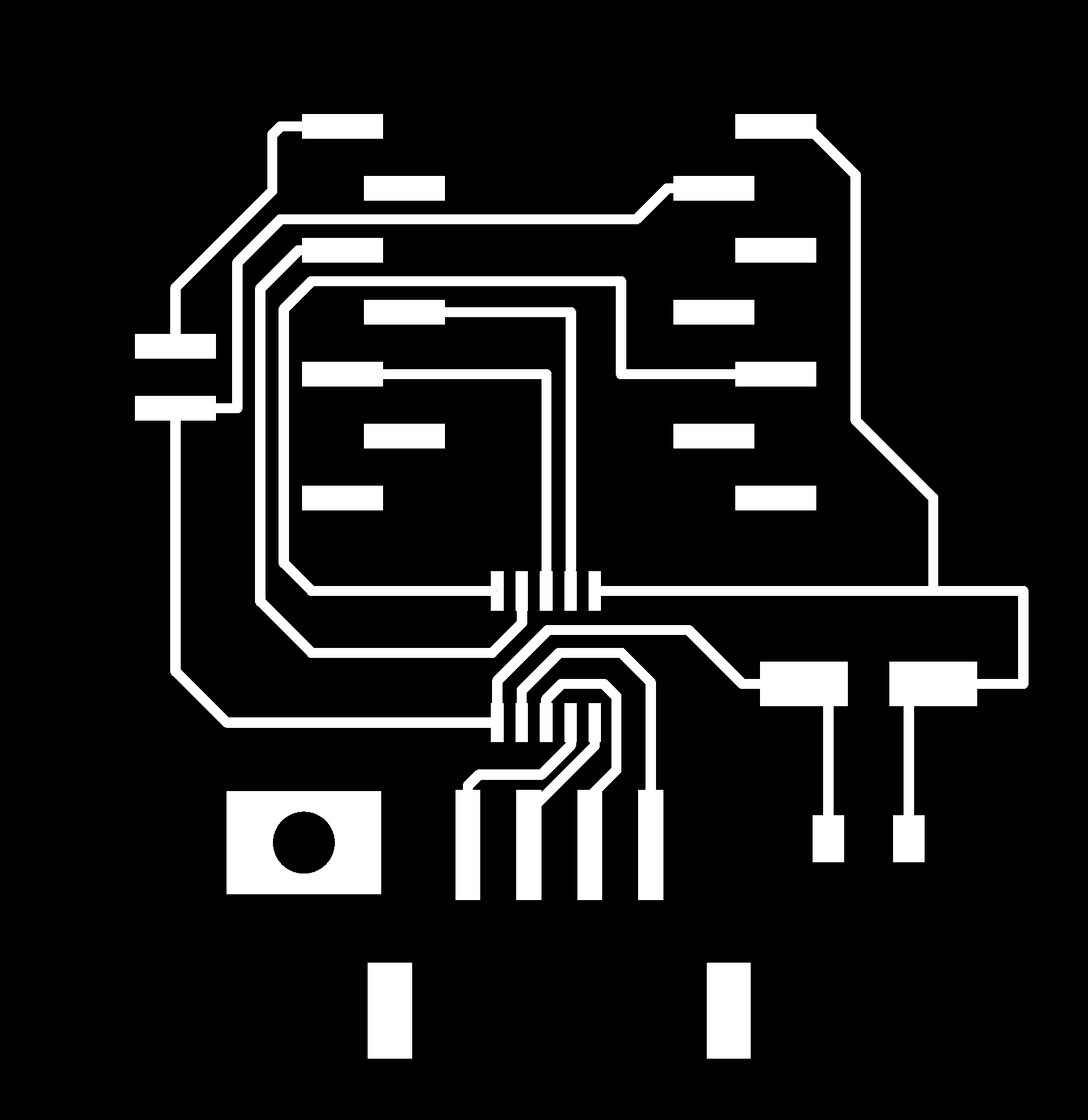 |
Because the traces and pads came directly from the verified prep-week PNG, I didn’t need to re-route anything — I only edited the artwork layer. The outline and hole files I used on the Genmitsu Kubico are below (same 45 mm scale):

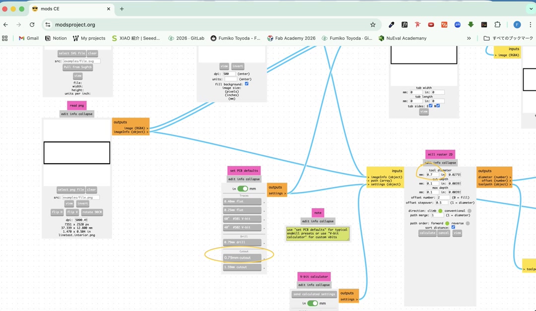
Workflow: 1. Opened the prep-week top-copper PNG in an image editor, masked the empty silk area and composited the flag into it. 2. Exported traces / holes / outline as separate 1000 DPI PNGs. 3. Generated toolpaths in mods and milled all three boards. 4. Stuffed the H-bridge IC, decoupling capacitors, pin headers and a connector using a mix of hand soldering and reflow with the heat gun — reflow for the H-bridge package, hand soldering for through-hole parts.
Traces – V-bit tuning
The trace cut was the part that took the most iteration. The board has very fine spacing around the H-bridge, so the cut-width setting in mods had to be dialled in carefully:
- First try – cut width 0.4 mm (V-bit preset, default). Too thick. The cutter ate into neighbouring traces and several of the thin lines came out broken.
- Second try – cut width 0.15 mm (my Week 08 Electronics Production setting). Too thin. The pads were barely separated from the surrounding copper, so shorts were likely.
- Final setting – 0.4 mm V-bit preset, tool diameter adjusted to 0.28 mm, offset number raised to 2. This gave a clean isolation around every pad without breaking any of the fine traces.
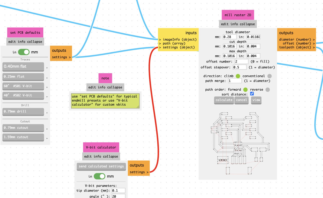
Cutout and holes – flat endmill
For the hole pattern and the board outline I started from the 0.79 mm cutout preset in mods, but the endmill we actually have stocked in Kannai is 0.7 mm, so I adjusted the tool diameter down to 0.7 mm before generating the path. After that change the holes and outline cut cleanly with no rework needed.
2. 3D-printed accessories
I designed and printed the small parts that made the machine usable as a calligraphy setup rather than just a plotter:
| image | name | description | design file |
|---|---|---|---|
 |
decorative feet | Four feet for the aluminum frame legs so that the raw cut metal won’t touch the table | decorative feet |
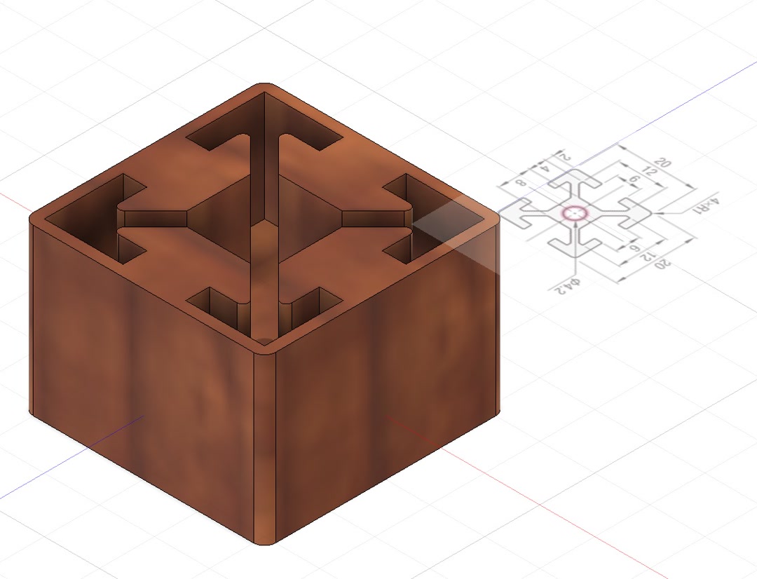
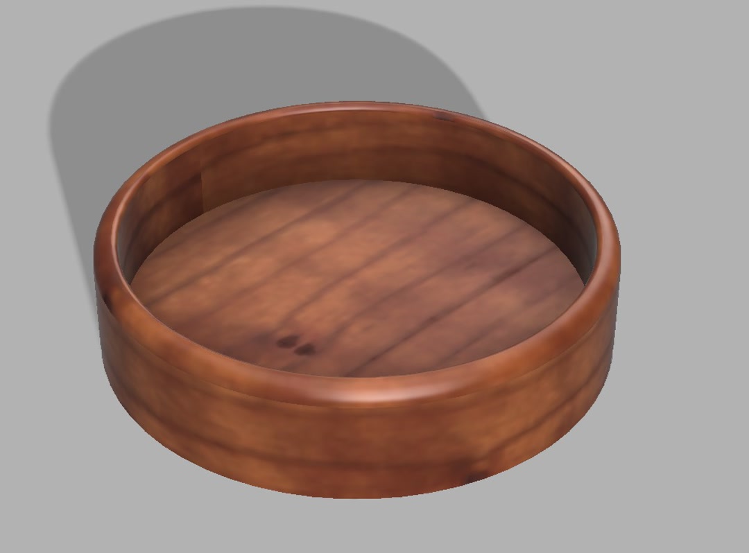 |
water dish | a small cylindrical dish that holds the water the brush is re-wet in between strokes. It is made lower in the end than the hero image above. | water dish |
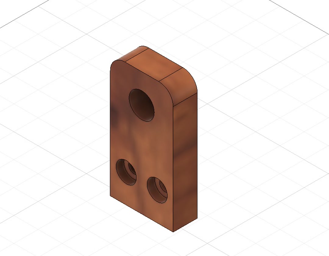 |
limit switch mount | brackets for mechanical limit switches on X and Y; I reused the limit-switch model from the 2025 Fab Lab Kannai BOM and made adjustment for the Z axis of our model | limit switch |
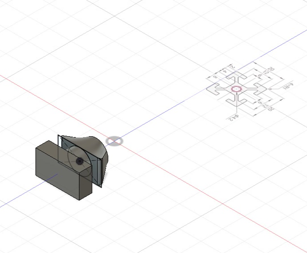 |
spacer | Small spacers used to fill the gap in aluminum frame and the drawing unit. (but not used at the end) | spacer |
3. Assembly contributions
During machine build I also:
- Measured and tensioned the Kevlar thread for the CoreXYZ belts. Because the geometry is sensitive to thread length, I cut and routed each loop carefully so the gantry stayed square.
- Helped debug the gantry alignment after a crash that loosened one of the thread loops.
4. Final touch
I laser-cut a set of personal 落款 (rakkan) stamps from gum-rubber mat so that the machine-stroked calligraphy would look properly finished — a hand-pressed red stamp in the corner is the traditional way to sign a Japanese brush piece. One stamp per team member, including Yuichi-san, our instructor.:
| Yuichi-san | Kieran | Youssef | Fumiko |
|---|---|---|---|
 |
 |
 |
 |
Problems we ran into (and how we solved them)
A short list of the issues I was directly involved in — the full list, including firmware issues, is on the group page.
- Z-axis travelled twice the expected distance. Root cause: the lead screw was a 4-start, not a 2-start as we had assumed in the firmware constants. Fixed by dividing the Z steps/mm by two.
- Limit switch caused software freezes. The initial ISR blocked inside an interrupt; Kieran refactored it into a flag-based check in the main loop and I re-designed and re-seated the switch connectors.
- Kevlar tension loss after crash. Re-cut and re-tensioned the loops; added a “home first, then move” step to the operating procedure.
Possible improvements
Covered in more detail on the group page, but from my side:
- Current z-axis movement is sliding in from left to right, and sliding up from right to left, which already looks nice, but I would add more finer strokes using the stroke type information in KanjiVG.
- To do so we would need a finer control of z-axis. If Quentin the inventor of CoreXYZ released his sample code, it would be much appreciated.
Design files
All files I contributed are in docs/design_files/week12/:
- top_japan.png – my board
- top_canada.png – Kieran’s board
- top_siria.png – Youssef’s board
- milloutline.png – board outline
- holes.png – hole pattern
Checklist
- [x] Documented the machine building process to the group page
- [x] Documented my individual contribution on this page
- [x] Linked to the group page from this page (and linked back from the group page)
- [x] Shown how the team planned, allocated tasks and executed the project (group page)
- [x] Described problems and how the team solved them (group page)
- [x] Listed possible improvements (group page)
- [x] Included design files (group page + this page)
- [x] 1-min 1920×1080 MP4 video + 1920×1080 PNG slide on the group page