Portrait Drawing Robot
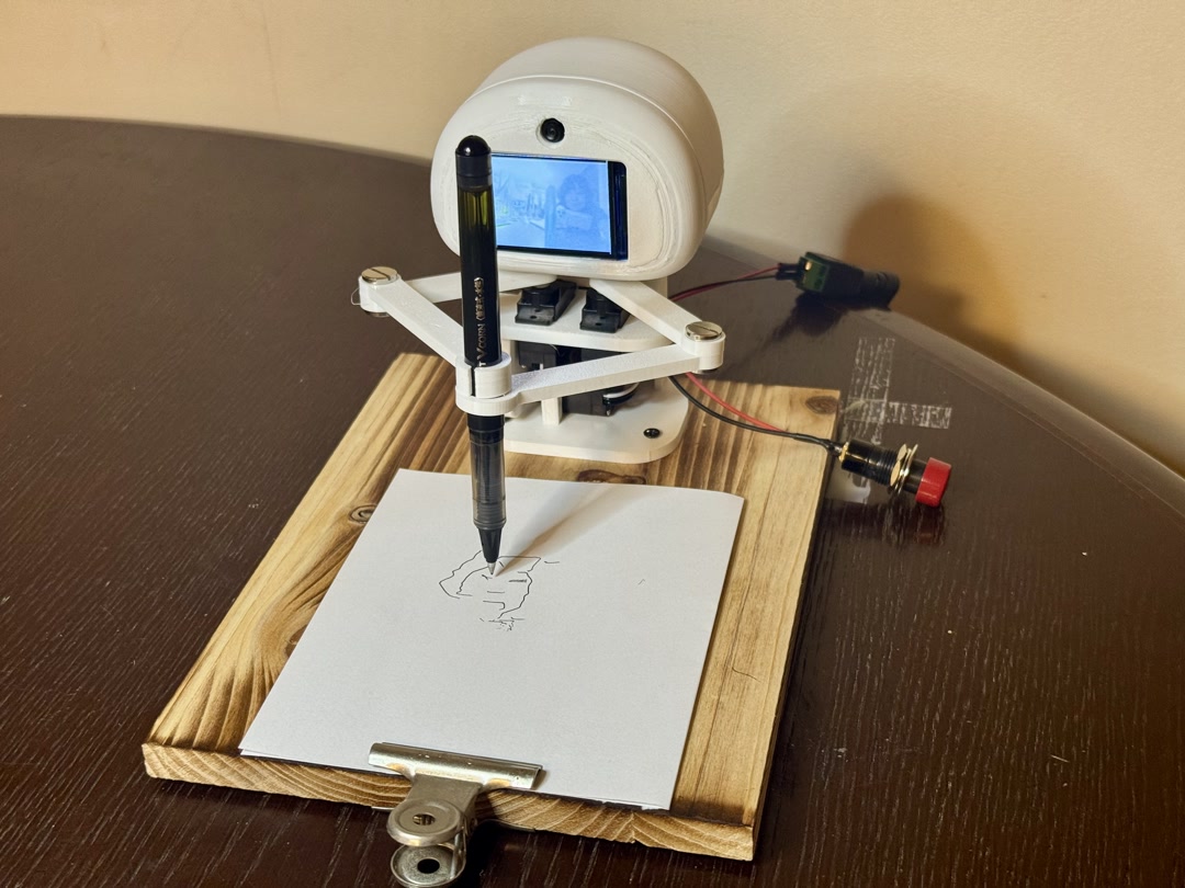
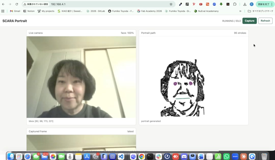
My final project is a small portrait-drawing robot. When a person stands in front of it and presses the button, the robot captures one camera frame, turns the face into drawing strokes, and draws the portrait with a five-bar arm.
Overview
The robot runs as a standalone embedded system. It uses a Seeed Studio XIAO ESP32S3 Sense, OV3660 camera, TFT display, push button, custom serial-servo PCB, three FeeTech SCS0009 servos, a 3D-printed five-bar linkage, and ESP-IDF/C++ firmware.
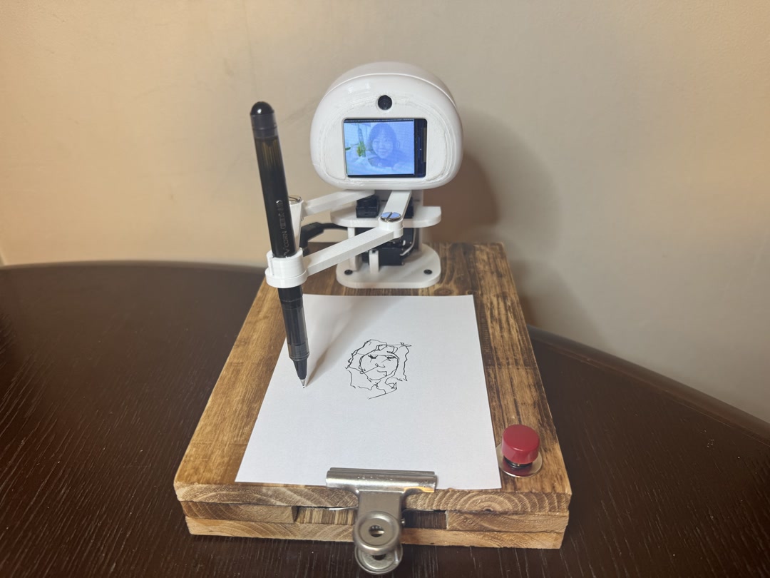
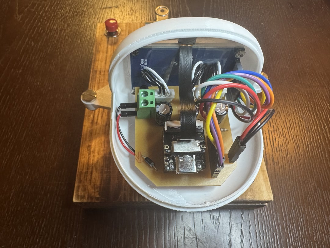
After the final presentation, I tidied the loose switch and power cables and moved the arm’s initial position sideways so it is less visible to the camera before capture.
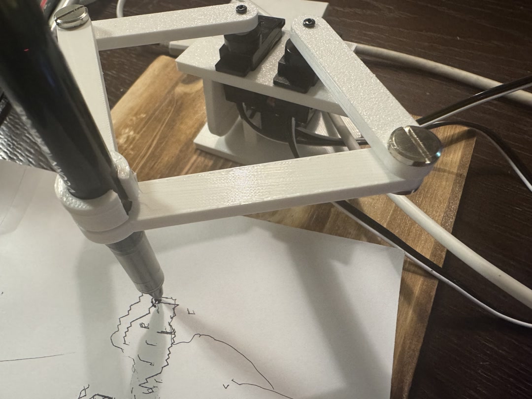
| Before system integration | After system integration |
|---|---|
 |
 |
System Integration
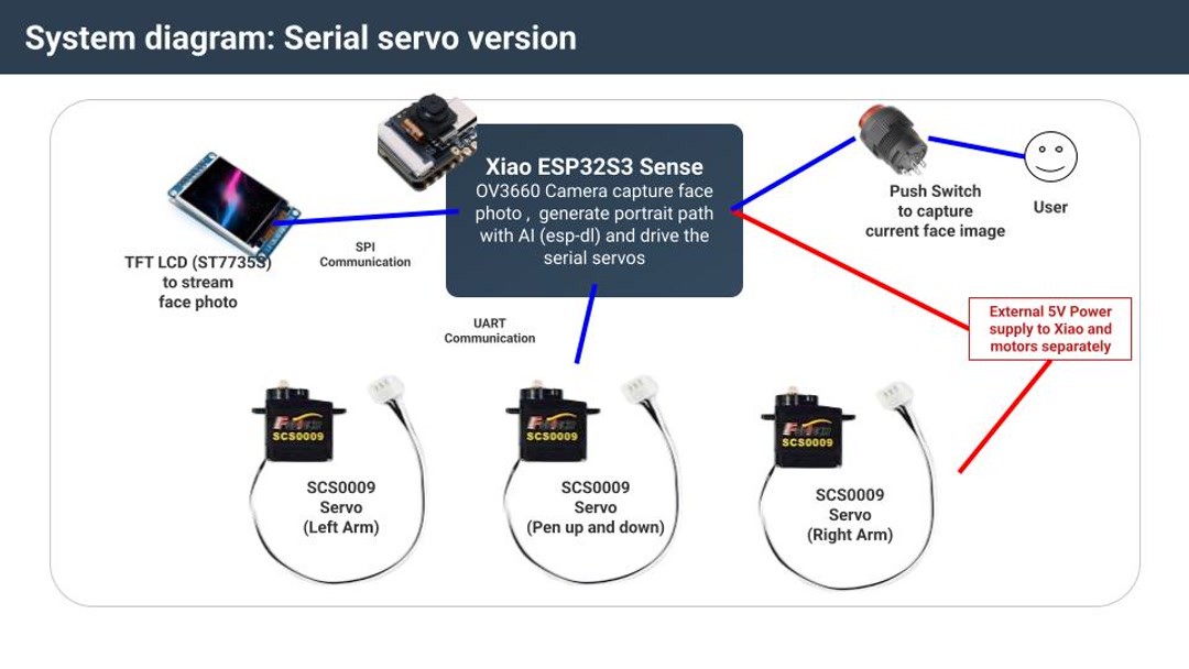
camera preview -> button capture -> face/image processing -> portrait strokes
-> five-bar inverse kinematics -> serial servo commands -> drawing on paper
The whole pipeline runs on the XIAO. The TFT display and button make the robot usable without a laptop, and the custom PCB connects the XIAO, TFT, button, external 5 V power, and three serial servos. The servos are powered from an external 5 V supply with common ground to the XIAO.
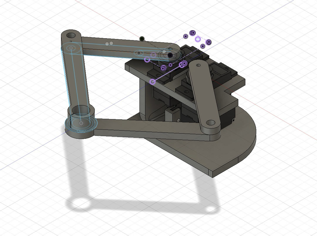
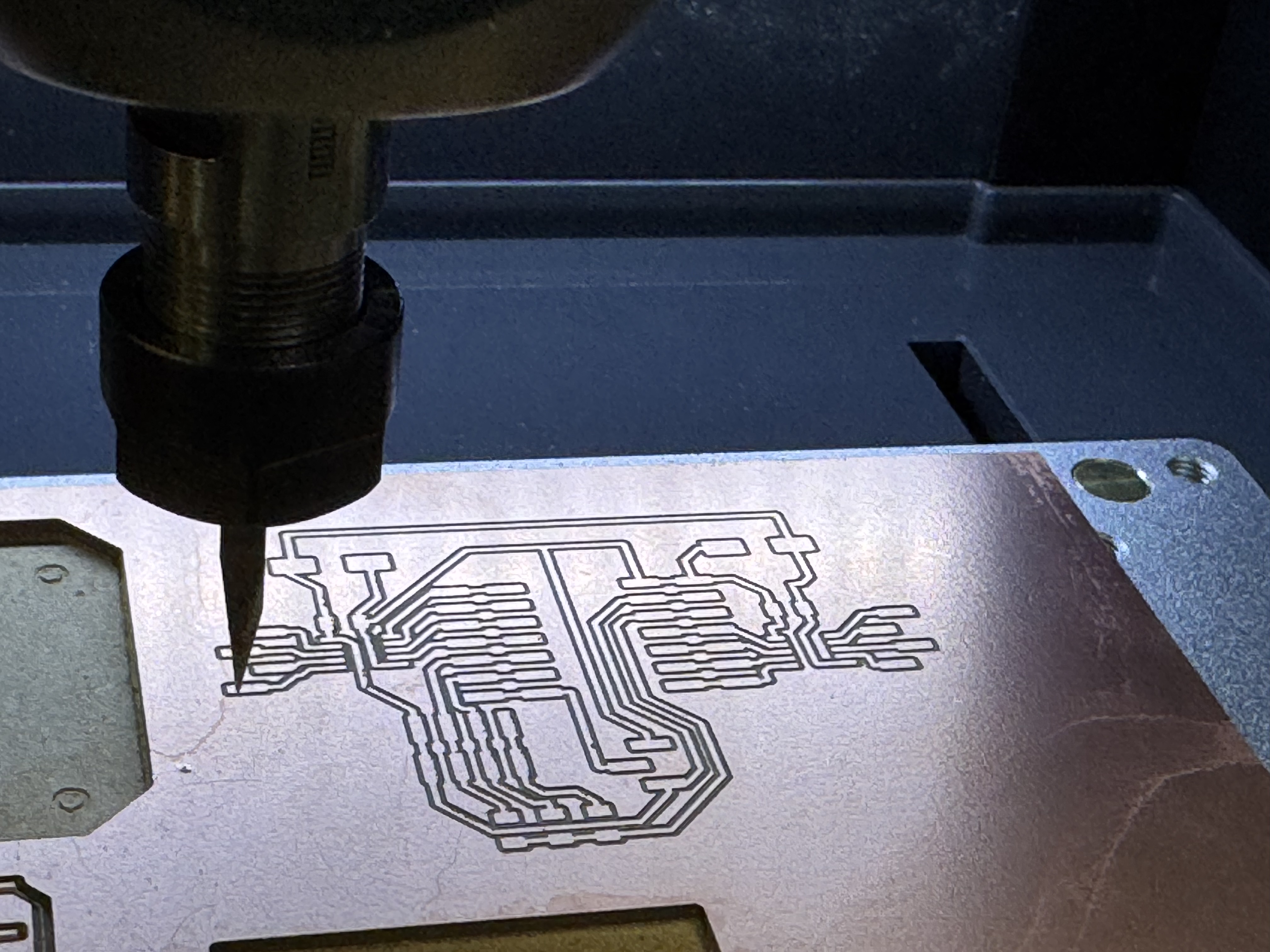
Fabrication
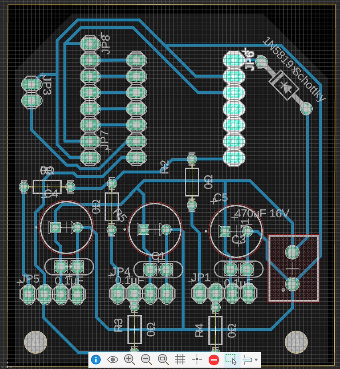
I designed the mechanism in Fusion 360, 3D printed the body and linkage parts, milled the custom PCB, soldered the components, and assembled everything inside the robot. The final drawing area is about 65 mm wide by 50 mm high.
Software
The final firmware is an ESP-IDF/C++ project. I built it by starting with small tests for camera capture, TFT display, button input, face detection, image conversion, stroke generation, serial-servo communication, and five-bar inverse kinematics.
main/main.cppstarts the integrated application.main/portrait_pipeline.cpphandles camera preview, face/image processing, and stroke generation.main/plotter_pipeline.cpp,main/fivebar_ik.cpp, andmain/scs_servo.cpphandle drawing motion and servo control.
Earlier in the project I tried a MicroPython path because it was easier to understand and modify quickly. I later returned to ESP-IDF/C++ because I needed ESP-DL face detection for the final on-device pipeline.
Bill of Materials
This is the estimated BOM for one complete robot. The FE-URT-1 board was used during prototyping and debugging, but it is replaced by my custom PCB in the final assembly.
| Category | Item / specification | Qty. | Made or bought | Source | Est. unit cost | Est. subtotal |
|---|---|---|---|---|---|---|
| Controller | Seeed Studio XIAO ESP32S3 Sense | 1 | Bought | Akizuki | ¥2,660 | ¥2,660 |
| Camera | OV3660 camera module with 75 mm cable | 1 | Bought | AliExpress | ¥1,273 | ¥1,273 |
| Display | 1.8-inch SPI TFT LCD, ST7735S | 1 | Bought | Amazon Japan | ¥899 | ¥899 |
| User input | Momentary push button | 1 | Bought | Akizuki | ¥90 | ¥90 |
| Actuators | FeeTech SCS0009 serial bus servo | 3 | Bought | Akizuki | ¥1,680 | ¥5,040 |
| Power | Regulated 5 V 3 A DC adapter | 1 | Bought | Akizuki | ¥1,100 | ¥1,100 |
| Electronics | Copper-clad PCB board | 1 | Made | Yodobashi | ¥469 | ¥469 |
| Electronics | Schottky diode | 1 | Assembled | Akizuki | ¥10 | ¥10 |
| Electronics | 470 uF capacitors | 3 | Assembled | Akizuki | ¥10 | ¥30 |
| Electronics | 0.1 uF capacitors | 3 | Assembled | Akizuki | ¥25 | ¥75 |
| Electronics | 0 ohm jumper resistors | 3 | Assembled | Akizuki | ¥1 | ¥3 |
| Electronics | Pin socket | 1 set | Assembled | Akizuki | ¥80 | ¥80 |
| Electronics | Pin header | 1 set | Assembled | Akizuki | ¥35 | ¥35 |
| Electronics | Wires | 1 set | Assembled | Amazon Japan | ¥570 | ¥570 |
| Electronics | Terminal block, 5 mm | 1 set | Assembled | Akizuki | ¥20 | ¥20 |
| Electronics | Heat-shrink tubing | 1 set | Assembled | Akizuki | ¥40 | ¥40 |
| Mechanism and enclosure | PETG filament for links, pen lift, body, and head | Approx. 300 g | Made | Amazon Japan | ¥2,565/kg | ¥800 |
| Hardware | Chicago screws for linkage | 1 set | Bought | Amazon Japan | ¥1,627 | ¥1,627 |
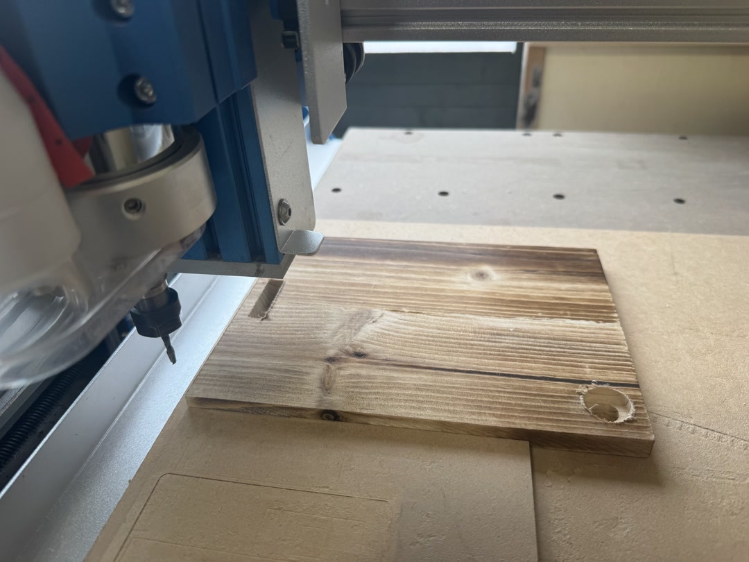
| Drawing surface | Wooden base board | 3 | Cut/engraved | Local shop | ¥110 | ¥330 |
| Consumables | Pen | 1 | Bought | Local stationery shop | ¥100 | ¥100 |
| Consumables | Drawing paper | 1 pack | Bought | Local stationery shop | ¥100 | ¥100 |
| Development tool | FEETECH FE-URT-1 servo interface board | 1 | Bought | Akizuki | ¥1,660 | ¥1,660 |
| Development power supply | Regulated 6 V 2.8 A DC adapter | 1 | Bought | Akizuki | ¥1,100 | ¥1,100 |
| Final robot total | ¥15,351 | |||||
| Total including development tools | ¥18,111 |
The estimates exclude shipping and failed prototype parts.
Design Files and Source Code
- 3D design: SCARA robot mechanism
- PCB design: serial servo board
- Source code: XIAO portrait ESP-IDF project
Where This Project Uses Fab Academy Skills
This project combines 2D/3D design, 3D printing, PCB milling, electronics design and production, embedded programming, input/output devices, interface design, and system integration. The main made parts are the 3D-printed mechanism and enclosure, the milled PCB, and the firmware.
Evaluation
The final robot is successful if it runs standalone, captures a face, generates a portrait path, draws it with the five-bar linkage, and provides downloadable design files and source code.
Reflections
It was hard to control the five-bar linkage well enough to draw clearly. It still has room for improvement. But all in all, I am so proud that I designed the PCB and the 3D model from scratch and completed the robot. I will make more robots like this in the future.
License

I chose the Creative Commons Attribution-ShareAlike 4.0 International license for my final project. I was inspired by open drawing robot projects, especially OSTR: Open Source Turtle Robot, and I would like this robot to be something other people can study, modify, and build on.
Acknowledgements
Thank you to Yuichi-san and Henk for support and advice. Yuichi-san helped me think through electronics choices earlier in the project and final packaging decisions later on. I also studied existing SCARA and drawing robot projects, including the Fab Academy SCARA Drawbot, BrachioGraph, CNC drawing arm projects, and OSTR.
I used Claude Code and Codex as coding and writing partners during the project. I reviewed, tested, edited, and integrated the generated code and text myself.
Checklist
- [x] Made the final slide,
presentation.png, at 1920 x 1080 pixels with my name, project name, Fab Lab name, project image, and brief description. - [x] Made the final video,
presentation.mp4, about 1 minute long, 1080p, and under the Fab Academy size target. - [x] Made this separate final project page to summarize and document the project.
- [x] Included the BOM for the project.
- [x] Linked from this page to the weeks where I worked on the final project.
- [x] Documented the system integration.
- [x] Linked to
presentation.pngandpresentation.mp4in the root of the website. - [x] Included downloadable original design files and source code.
- [x] Included the license I chose.
- [x] Acknowledged work done by others.
Weekly Progress Log
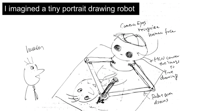
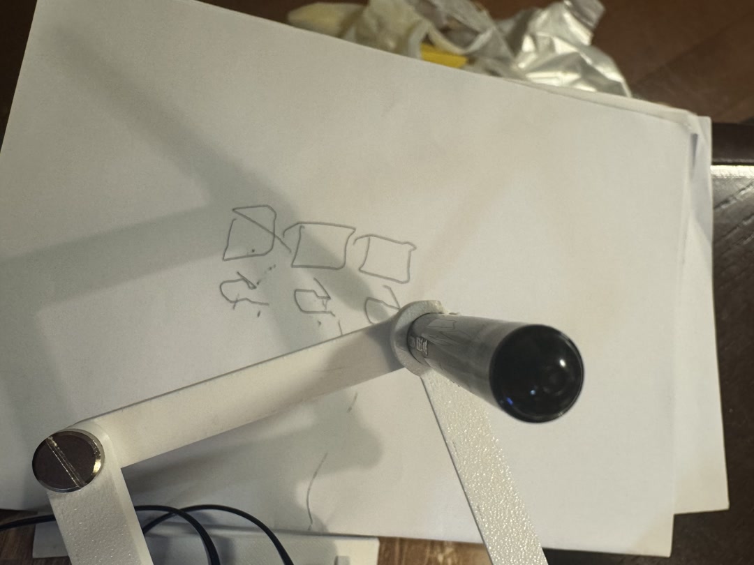
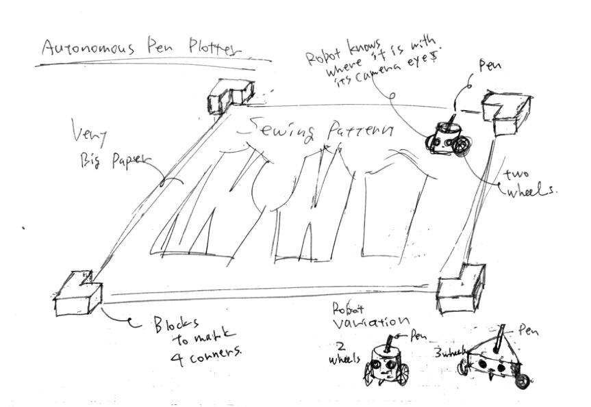
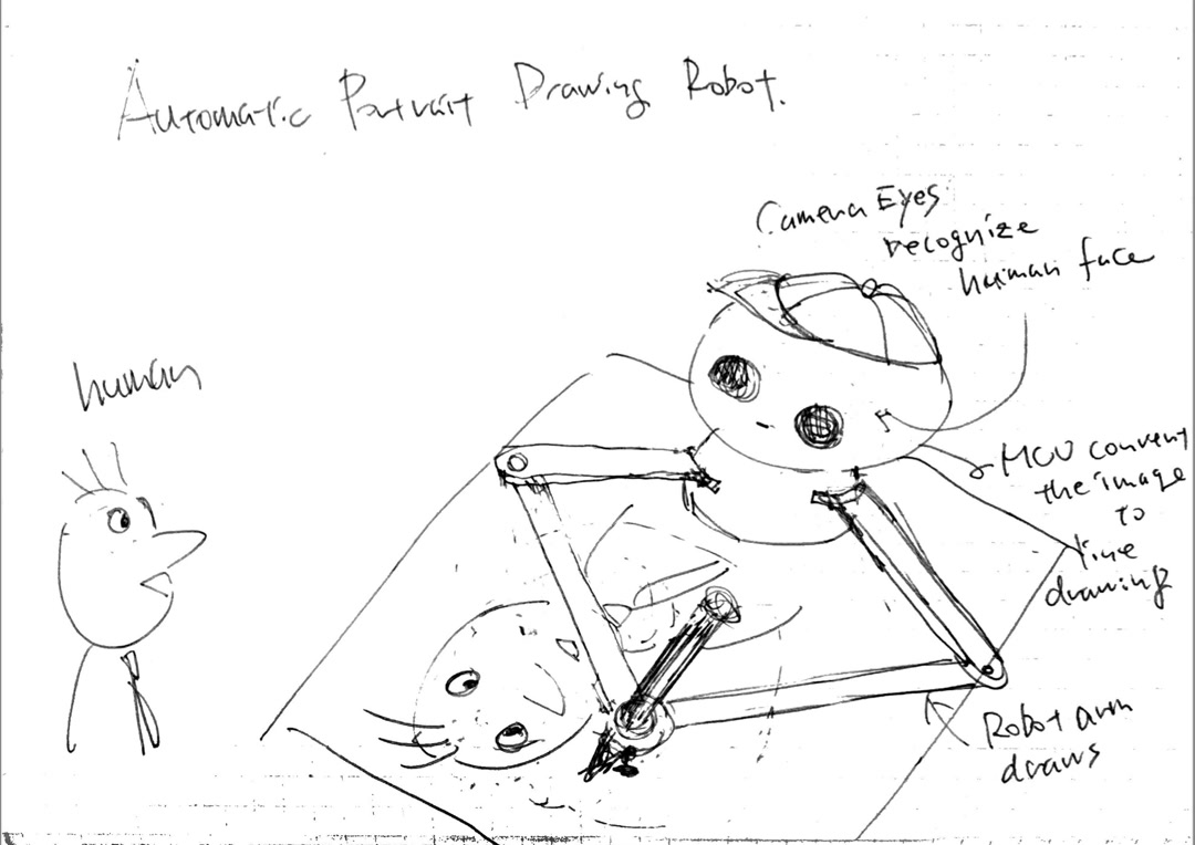
I started with the idea of an autonomous pen plotter that could draw on a large surface, especially for sewing patterns or sumi-e drafts. In Week 1, I sketched that first direction.
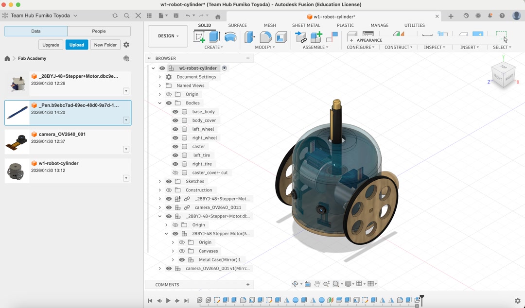
In Week 2, I made an early 3D CAD model with small stepper motors and camera eyes. At this stage the project was still more like a mobile plotter than a portrait robot.
Around Week 6 and Week 7, the idea changed. I began with a stepper-motor electronics board, then realized that a portrait-drawing robot with camera eyes and robot arms felt more exciting and more personal.
In Week 8 and Week 10, I tested the electronics and motion basics. My early board could drive two stepper motors and a servo, which proved that I could control actuators from my own electronics, even though I later moved away from the stepper direction.
In Week 11, I replaced the controller with the XIAO ESP32S3 Sense and got the OV3660 camera working. This was the first time the robot really had eyes.
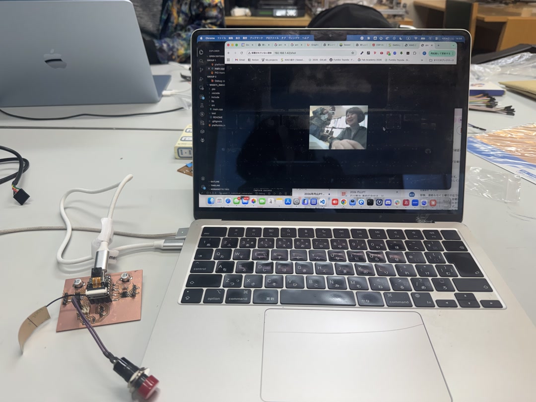
In Week 15, I built the first “brain” of the robot: an ESP-IDF app that captured an image, detected a face on-device with ESP-DL, generated portrait strokes, and served the result to a browser. This showed that the XIAO could handle the vision and portrait-generation parts without cloud processing.
In Week 16, I made the system integration plan and temporarily moved toward MicroPython because it was easier for me to understand quickly. Later I returned to ESP-IDF/C++ because I needed ESP-DL face detection for the final version.
In Week 18, I focused on the five-bar mechanism, serial servos, power, and the custom PCB direction. The project became much clearer: the robot needed to be compact, self-contained, and powered safely from an external supply.
In Week 19, I documented the remaining integration work, license, dissemination plan, PCB iterations, and final project management. The final days were about making the separate working parts behave as one small robot.