Week 07: Computer-controlled machining
Ironing Stand
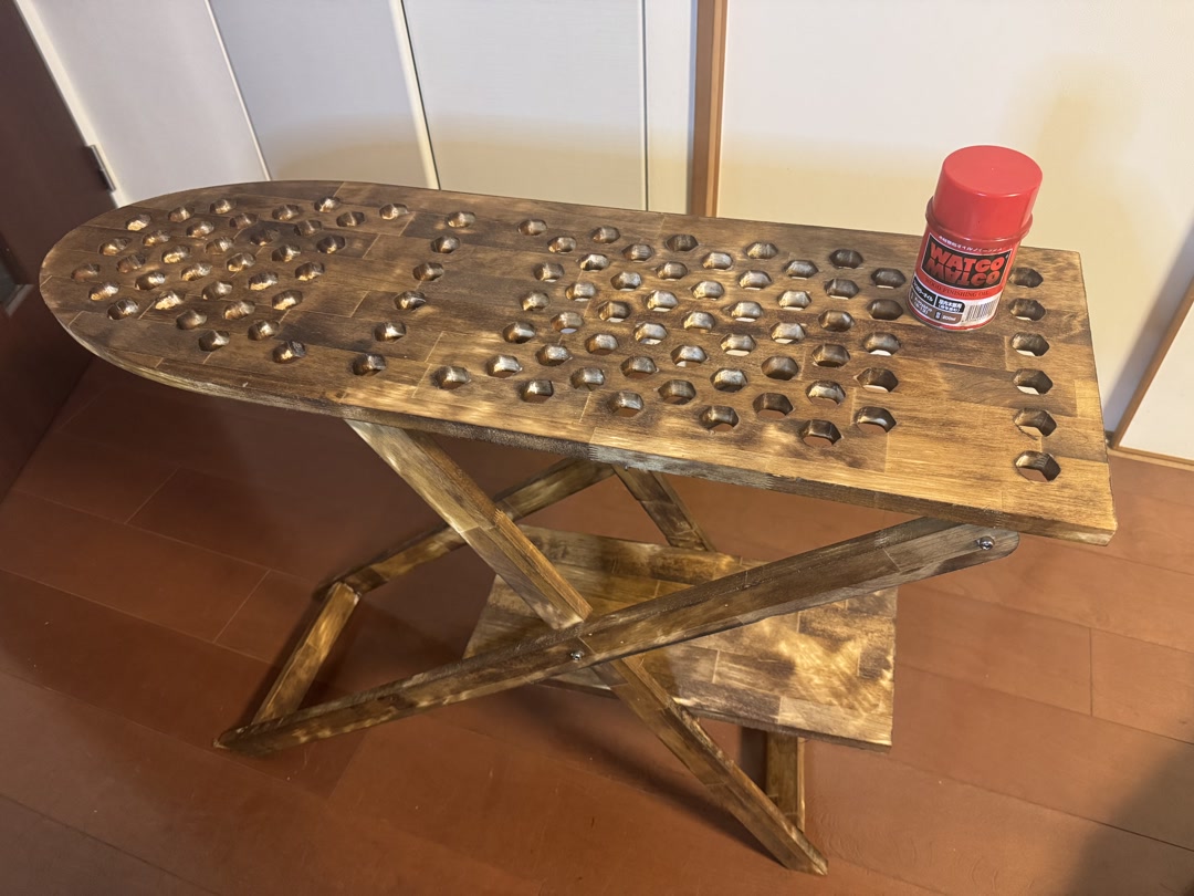 Ironing Board — Designed and milled an ironing stand. Finished with walnut-colored WATCO oil.
Assignments
Group assignment:
- do your lab’s safety training
- test runout, alignment, fixturing, speeds, feeds, materials, and toolpaths for your machine
Individual assignment:
- make (design+mill+assemble) something big (~meter-scale)
- extra credit: don’t use fasteners or glue
- extra credit: include curved surfaces
- extra credit: use three-axis toolpaths
1. Group Assignment
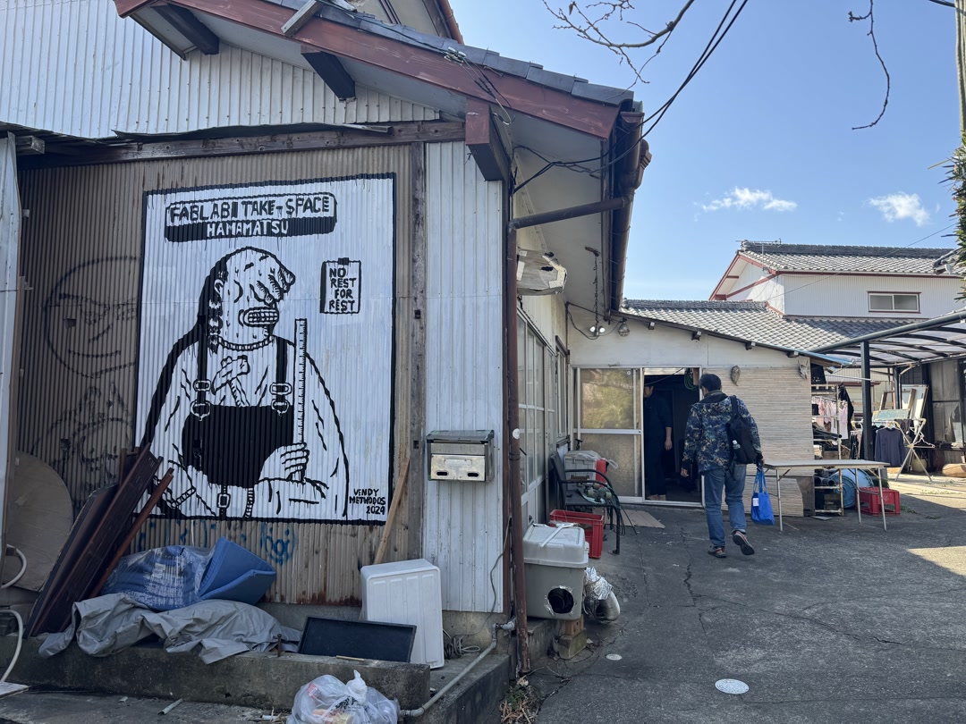
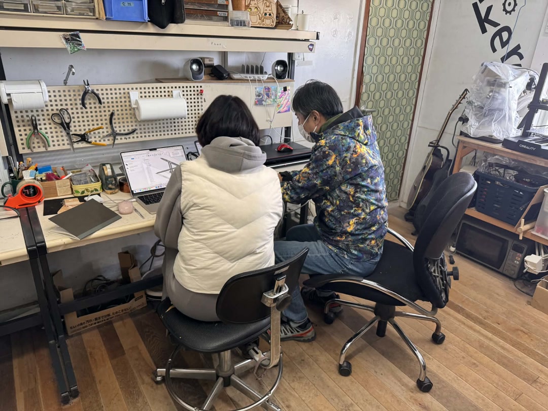
We traveled 240 km to FabLab Hamamatsu, where we could use a large CNC machine.
At first, I was intimidated by the size and noise of the machine, but I soon realized what an amazing opportunity it was to design and build something very large, as long as we followed the safety procedures. Thank you to Take-san of FabLab Hamamatsu for the warm welcome and training.
Safety procedures include:
- don’t wear loose clothing
- protect yourself with goggles, etc.
- securely chuck the tool
- secure the board with nails before cutting
- know how to stop the machine with both the physical machine button and the software button
- keep your eyes on the machine while it is working
- clean up the debris
FabLab Hamamatsu
2. Individual Assignment
2-1. Original Design
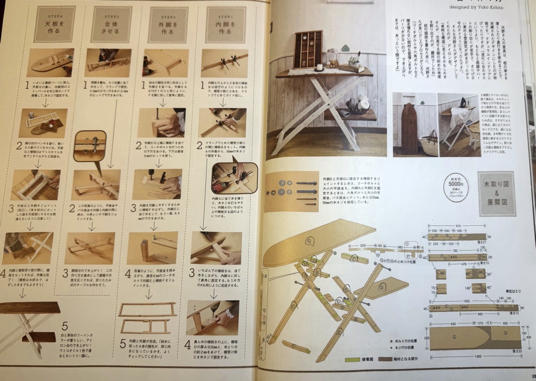
I designed an ironing stand based on a design from a beginner woodworking book, with the following changes:
- Unified the board thickness to 18 mm
- Instead of nailing the parts together, I designed them to press-fit.
- Added holes to the top board so that a steam iron can be used with a felt mat and cover sheet.
The beginner woodworking book:
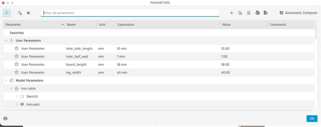
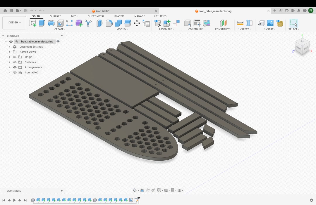
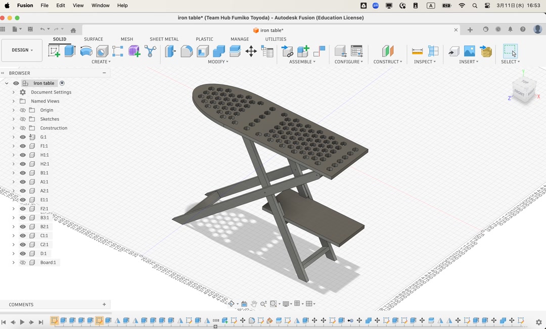
First, I made a 3D model in Fusion. I registered parameters so that the calculations would remain meaningful and reduce potential mistakes.
Then I proceeded with the design. I first created the textbook model without any press-fit features at home.
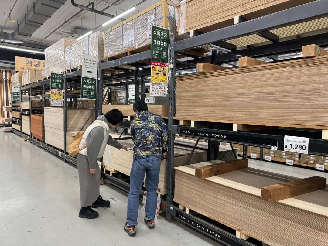
Just after arriving in Hamamatsu, we went shopping and selected a nice laminated pine board measuring 910 mm × 1820 mm × 18 mm. I did not have to change the board thickness parameter of 18 mm.
I received advice from Tamiya-san to use the dogbone technique to create press-fit features that account for the diameter of the end mill.
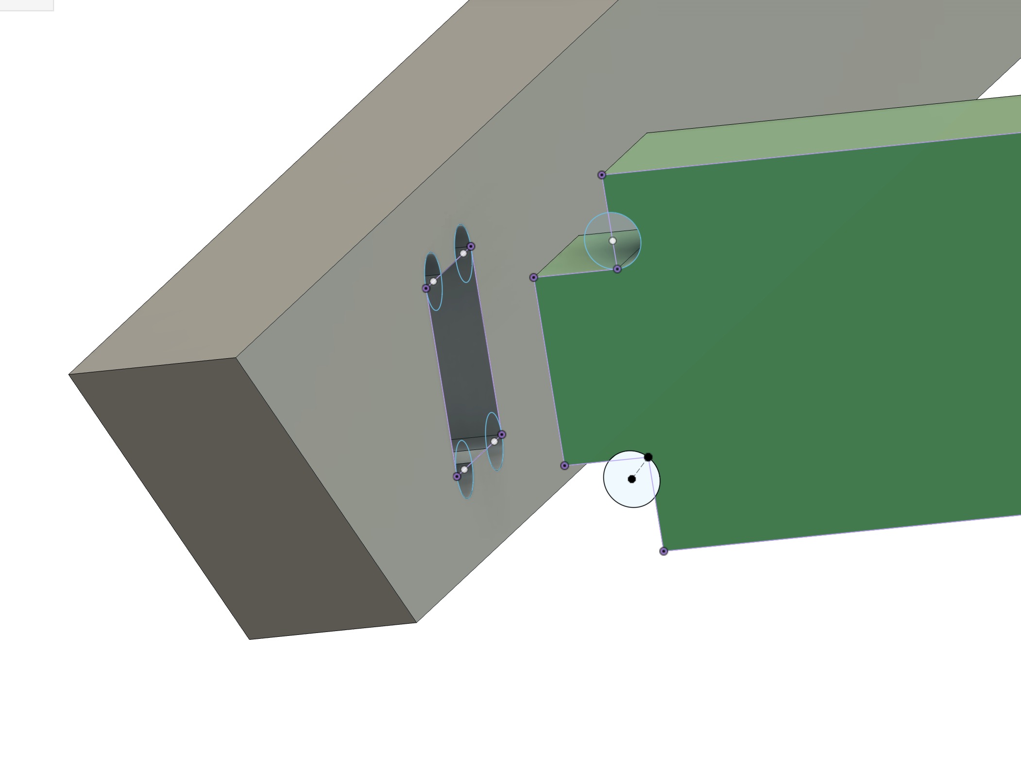
I applied dogbones where nails and screws were supposed to be used in the original design.
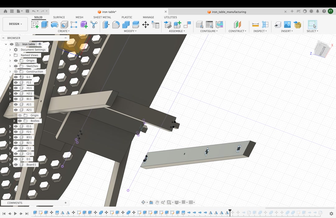
We also tested whether the folding movement was possible and rounded the corners where necessary.
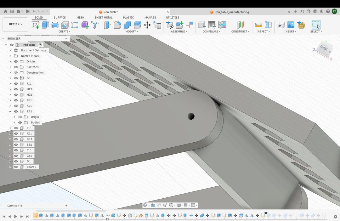
Now the Fusion model was complete.
I made the design change after we arrived in Hamamatsu, but it took me more time than I had expected.
2-2. Create CAM Toolpath
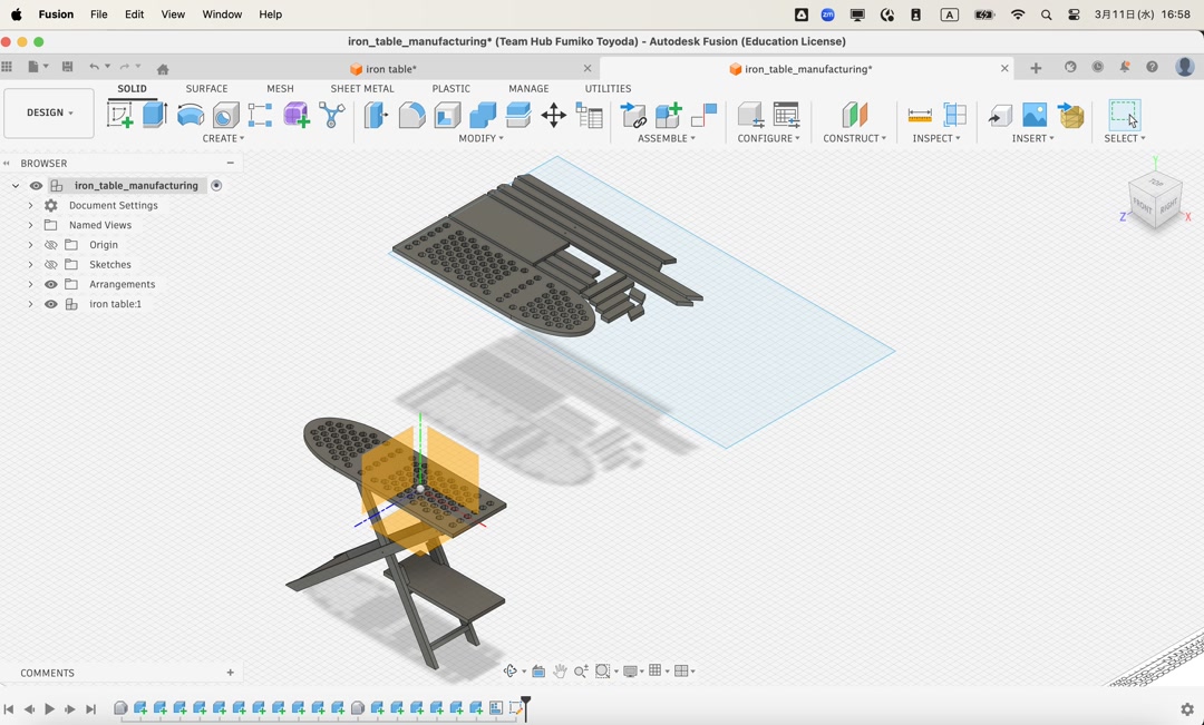
Before coming to Hamamatsu, I found a way to automatically arrange the parts flat using Fusion Manufacturing mode. However, I could not find a way to export the flat model as an AI or SVG file.
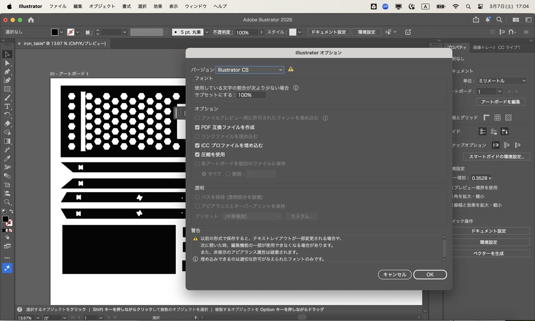
Tamiya-san taught me that the easiest and quickest way to export the paths was to use the Shaper utility in Fusion, export the faces one by one as SVG files, and place them in Adobe Illustrator. Saving the AI file in the old CS format was important so that it could be used with the Cut2D software in the next step.
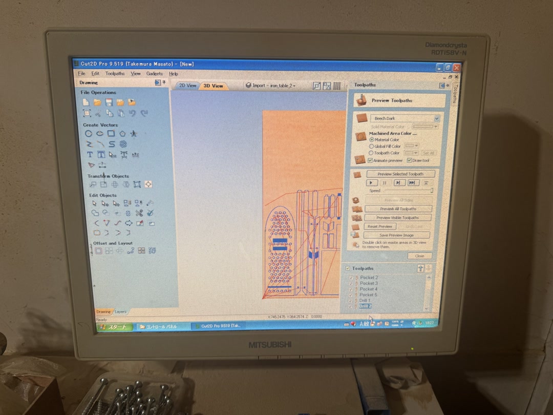
It was almost evening when we started cutting wood. First, we uploaded the Illustrator file to Cut2D.
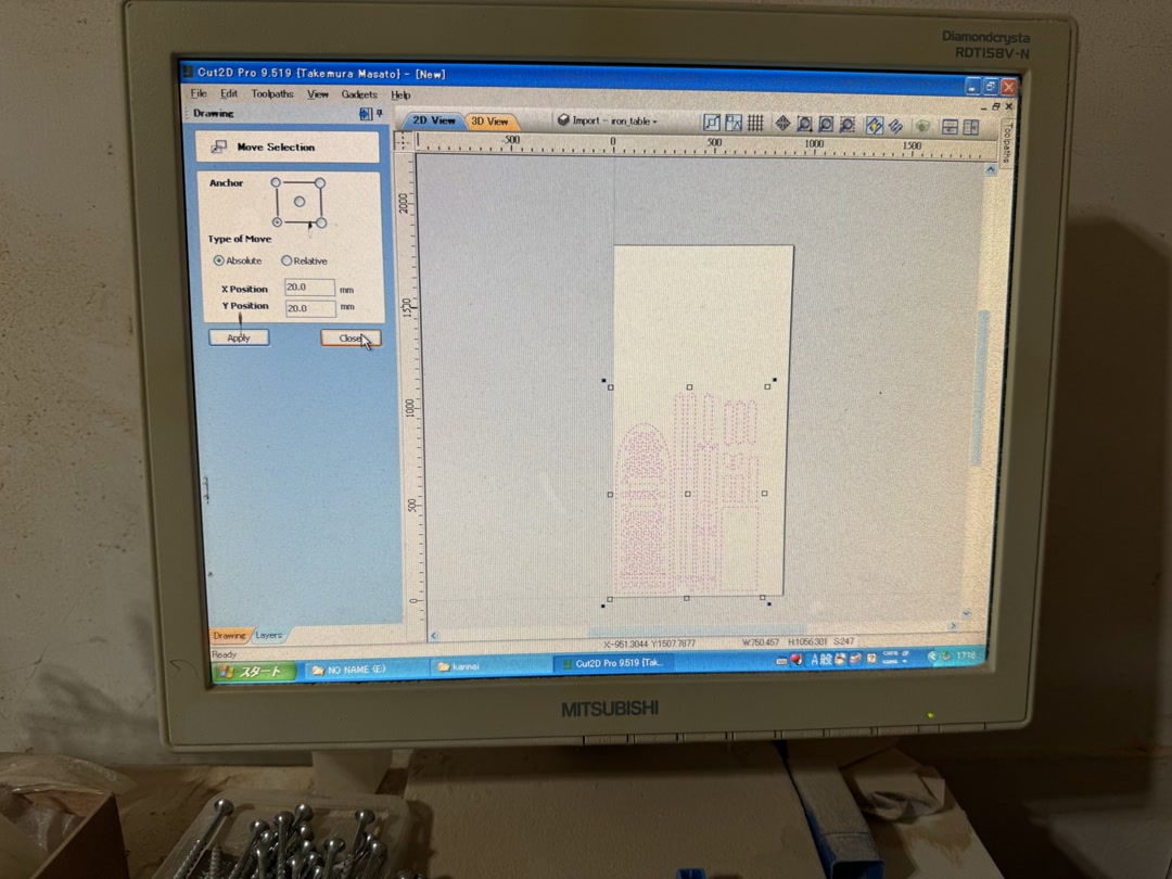
Then we configured the pocket toolpaths, profile toolpaths, and drill holes, and exported the toolpaths to Mach3, the machining controller.
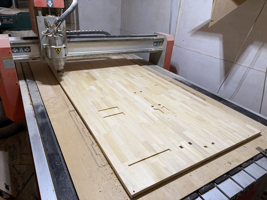
2-3. Milling
First, I drilled holes to fix the workpiece in place. Then I secured the workpiece with screws.
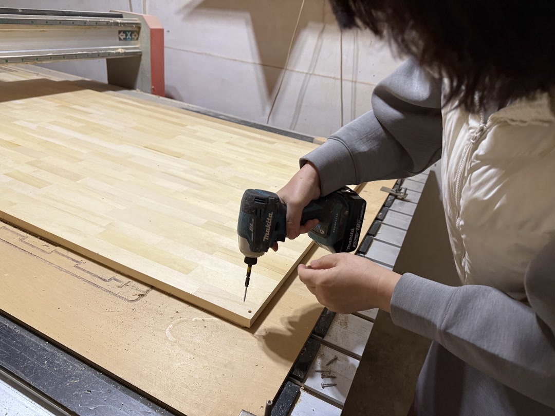
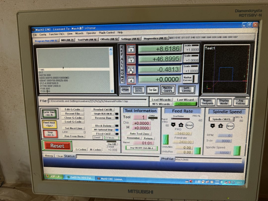
The machine was controlled using Mach3 CNC software, and I used the same settings as in the group assignment.
- Spindle speed: 10,000 RPM (reduced to ~8,000 via override)
- Feed rate: 2400 mm/min (reduced to ~1440 mm/min via override)
- Plunge rate: 600 mm/min Overrides were used to safely tune cutting conditions during operation.
Then we loaded the rest of the toolpaths into the controller.
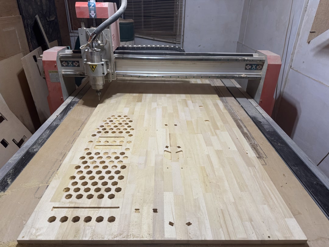
I found that the pocket was too deep, and there were cut marks where the end mill moved between cuts. Apparently, the Z-axis setting was not optimal, so we adjusted the machine settings and cut some extra material. After some trial and error, it was already 21:30 at night! I decided to bring the workpieces home.
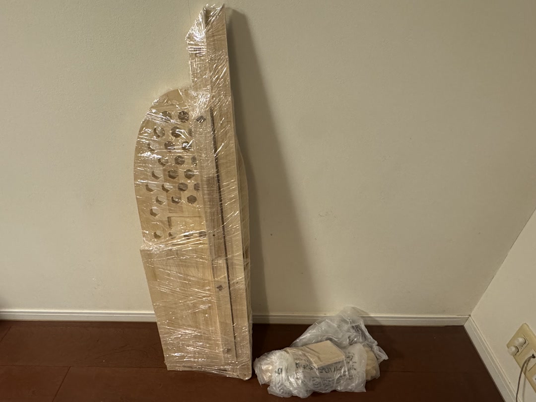
Only after I tried to fit the pieces together did I realize that I had completely forgotten about the clearances. The pieces did not fit together!
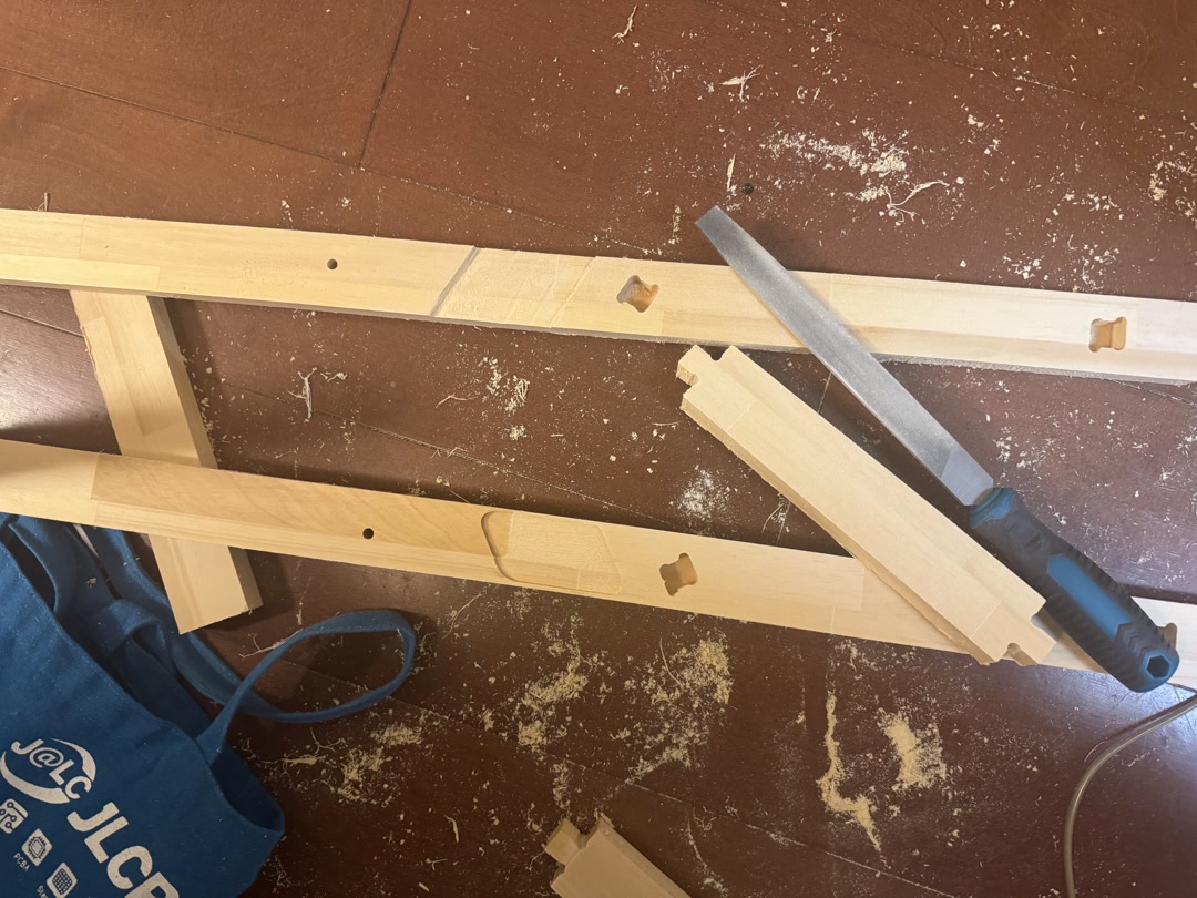
Since then, I have been filing the parts for what feels like forever. I think I am almost there, but I also realized that I needed to make some holes manually.
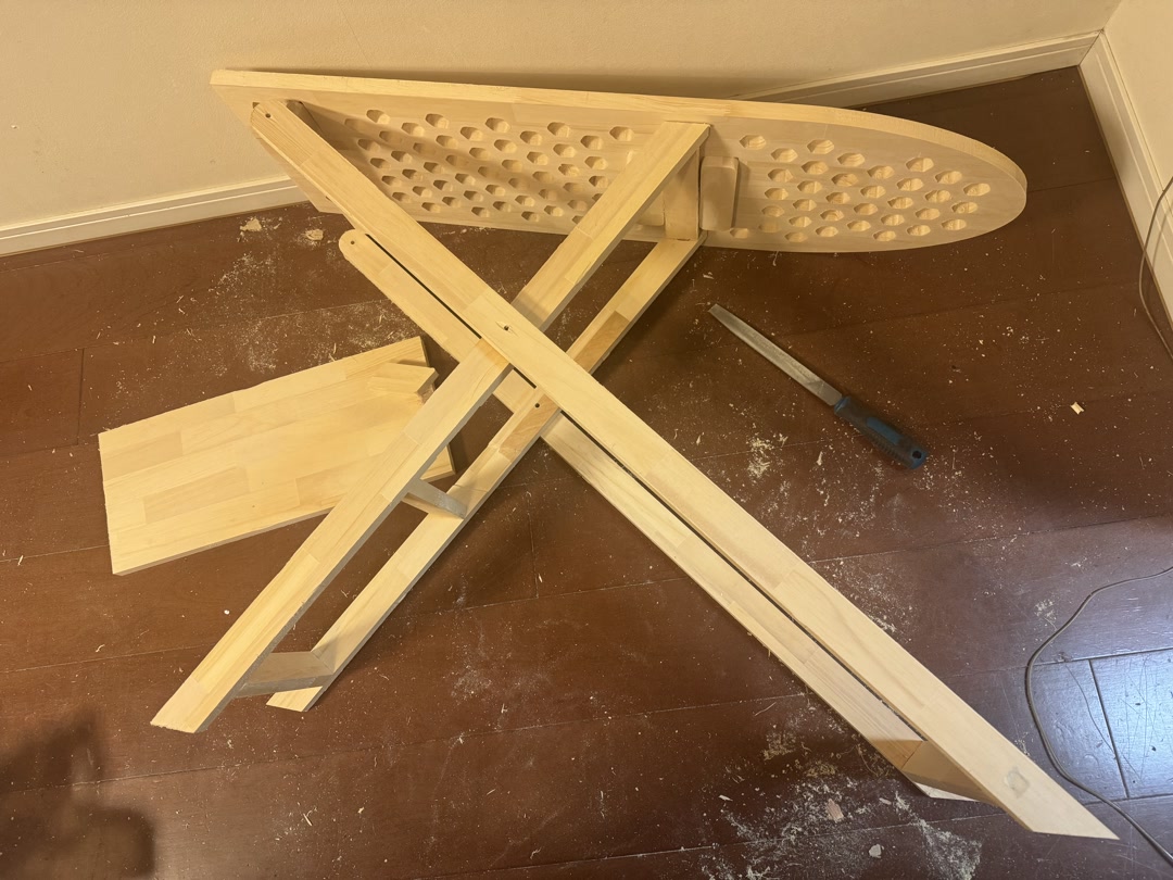
Finally, I managed to make the holes and assemble the stand. I finished it with WATCO wood finishing oil to give it a walnut color. If I were to actually use this for ironing, I would make a cloth cover. But I think the stand can also be used as a pretty antique-style side table as is.
Reflections
This was my first time using a large-format CNC router, and both the machine and the venue were new to me. I was initially intimidated by the size and noise, but I quickly appreciated what an extraordinary opportunity it was to design and machine something at this scale. I expected the main challenges to be learning the safety procedures and the software; the actual bottleneck turned out to be the design itself.
Several things went wrong. I was still making design changes after arriving at FabLab Hamamatsu, which cost significant time and added unnecessary pressure. I had forgotten to incorporate press-fit clearances into the parametric design, something I only discovered when the pieces would not fit together at home. The Z-axis offset was also misconfigured, leaving tool-travel marks across the surface and making some pockets too deep. The honeycomb venting holes were far more complex to mill than a simple drilled pattern would have been.
None of it was catastrophic. Patient filing and sanding brought the pieces close enough to assemble, but all of it was avoidable.
Next time: finalize the design and get it reviewed before the machining day; use the Shaper utility + Illustrator SVG workflow for 2D layout rather than Fusion Manufacturing’s auto-arrange feature; build clearances into the parametric model from the start; and use drilled holes for ventilation rather than complex cut patterns. The large CNC is an incredible machine once you plan carefully enough to use it well.
Design Files
Checklist
- [x] Linked to the group assignment page
- [x] Reflected on your individual page what you learned from your lab’s safety training
- [x] Documented how you designed your object and made your CAM toolpath
- [x] Documented how you milled and assembled your final product (including setting up the machine, fixturing, feeds, speeds, etc.)
- [x] Described problems and how you fixed them
- [x] Included your design files and ‘hero shot’ of your final product
AI usage
I used Codex for grammar checking and phrase refinement.