Final Project 2nd part Activities
Final Project
My Final Project consists of two part;
1. FABLAB.able Kinetic Seat Ver.2 as the improved version from my Fabricademy Final Project to be the base of my FAB Academy Final Project
2. Semi-Active Kinetic Seat controlling system development
2. Development of “Semi Active Kinetic Controlling System”
Revised Plan for “Semi Active Kinetic Controlling System” development (2026/09/01~2026/10/31)
I made the revised schedule of my Final Project as follows;
Orange color date will be the date to visit or communicate with FABLAB Kamakura.
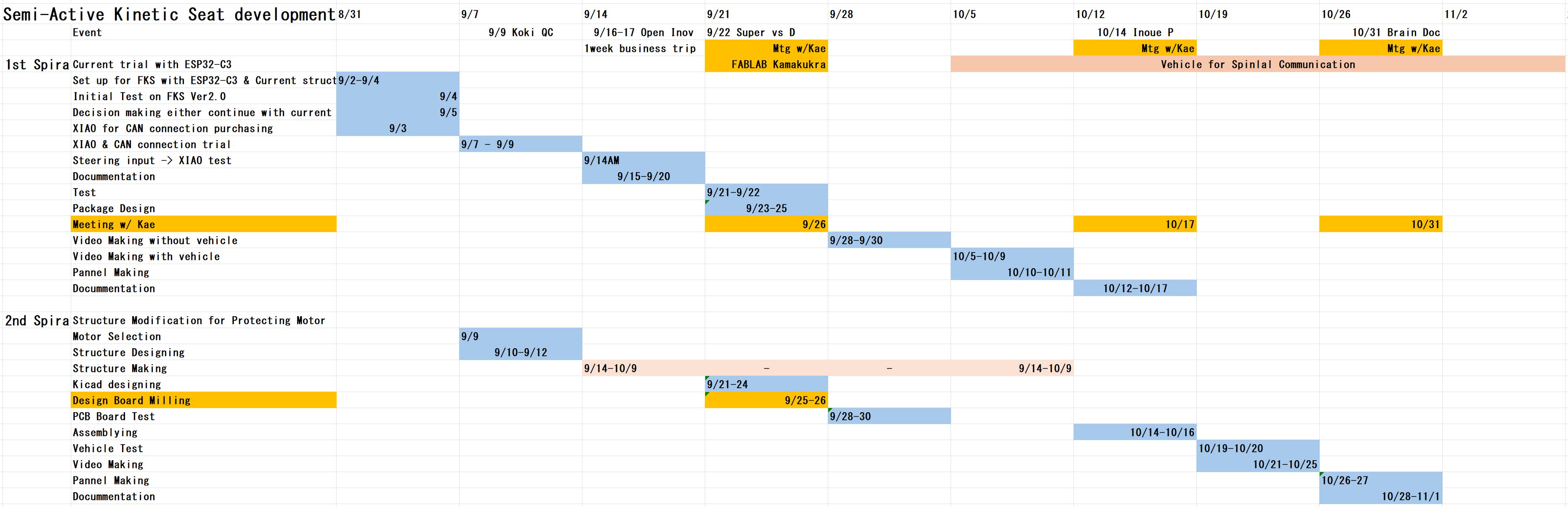
Here under is the 2nd revised schedule of my Final Project;
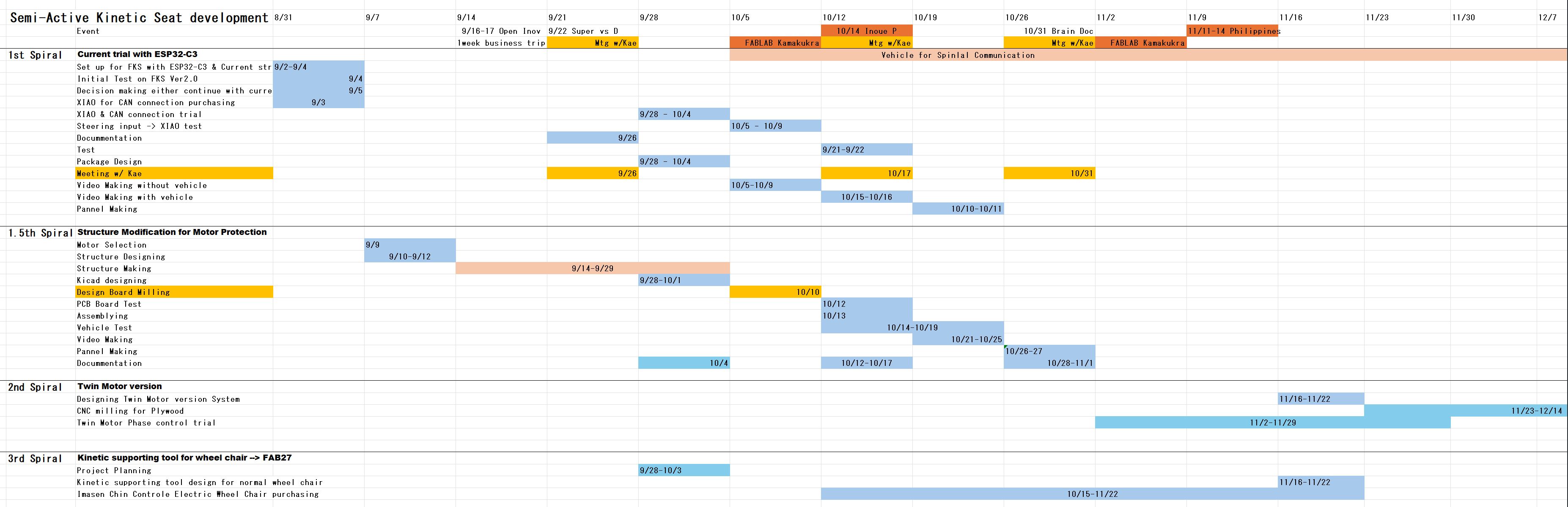
Rather than redesigning the entire motor mounting system as the 2nd spiral, I successfully improved the design through minor modifications, ensuring that excessive loads were no longer applied to the motor shaft as 1.5 spiral.
For my Fab Academy graduation, I will complete the 1.5 spiral as my final project. Afterward, I plan to continue developing the project through the second and third spirals, with a greater focus on product development.
Improvement of Servo Motor operational delay
I had relatively big delay of Servo Motor control by my Processing - Arduino input control in my week14.
Initially, the servo motor moved to the target angle received from Processing, but it immediately returned to its zero position even though the angle value in Processing had not changed.
Then, my instructor Maki tried to reduce the delay by following code on Arduino coding;
Preventing the Servo Motor from Returning to Its Zero Position
Arduino Coding by Maki.
#include <SCServo.h>

SMS_STS st;

#define S_RXD 20
#define S_TXD 21

const int iniPos = 2047; //Initial Position

int cPos=0; //current position
int cLoad=0; //current load
int tPos=0;

void setup()
{
  Serial1.begin(1000000, SERIAL_8N1, S_RXD, S_TXD);
  st.pSerial = &Serial1;
  st.WritePosEx(2, iniPos, 3400, 50);  // Set Initial Position
  // Set the same baud rate as the Processing serial connection
  // to receive the angle data correctly.
  Serial.begin(115200);
  delay(1500);
}


void loop()
{

  if(Serial.available()){
    //String s = Serial.readString();
    //int val = s.toInt();
    //int val=Serial.parseInt();
    // Read one complete angle command from Processing.
    // Using the newline character as a delimiter prevents a remaining
    // newline or incomplete serial data from being interpreted as angle 0.
    String s = Serial.readStringUntil('\n');
    //Receive data from "processing" until "\n" letter comes out

    // Update the servo target only when valid data has been received.
    // If no new angle command is available, the previous target position
    // is maintained instead of sending an unintended zero-angle command.
    if (s.length() > 0) {
      int val = s.toInt();


      tPos = map (val, -90,90, iniPos-2000, iniPos+2000); //

      // Send a new position command only after receiving a valid angle.
      // When no new command is received, the servo continues to hold
      // the last target position sent from Processing.
      st.WritePosEx(2, tPos, 3400, 800); // servo(ID1) speed=3400,acc=50,move to position=4095.
      Serial.println(tPos);
    }
    //delay(1300);
  }
  rcv_data(1);
    delay(10);

}

void rcv_data(int id){
  if(st.FeedBack(id) !=-1){  // ここで通信してよむ
    cPos = st.ReadPos(-1);  // メモリからよむ
    cLoad = st.ReadLoad(-1);
    Serial.print(cPos);
    Serial.print(" , ");
    Serial.println(cLoad);
  }
    //delay(100);

}
The main modified part is the following part;
From Serial.parseInt() –> readStringUntil(‘\n’)
Initial
In the initial program, the angle value was received using Serial.parseInt().
int val = Serial.parseInt();
Processing transmitted the angle as a numerical value followed by a newline character. For example:
30\n
Serial.parseInt() read the numerical value, but the newline character could remain in the serial buffer. During the next loop, Serial.available() detected the remaining character and called Serial.parseInt() again.
Because there was no valid numerical value following the newline character, Serial.parseInt() could return 0 after the timeout period. This unintended value was then converted into the center position of the servo:
tPos = map(val, -90, 90, iniPos - 2000, iniPos + 2000);
As a result, the servo received a new command corresponding to 0 degrees and returned to its initial center position.
Modified
Reading the Angle as a Complete Line
To solve this problem, Maki changed the serial data processing method. Instead of using Serial.parseInt(), the program now reads one complete line of data ending with a newline character.
// Read one complete angle command from Processing.
// Using the newline character as a delimiter prevents a remaining
// newline or incomplete serial data from being interpreted as angle 0.String s = Serial.readStringUntil('\n');
This method processes the numerical value and the newline character as one complete message. Therefore, the newline character is not left in the serial buffer and is not processed again as another angle command.
Ignoring Empty Serial Messages
Maki also added a condition to ensure that the servo command is updated only when a valid message has been received.
// Update the servo target only when valid data has been received.
// If no new angle command is available, the previous target position
// is maintained instead of sending an unintended zero-angle command.
if (s.length() > 0) {
int val = s.toInt();
The received string is converted into an integer only after confirming that it contains data.
The servo position command is also executed only inside this condition:
tPos = map(val, -90, 90, iniPos - 2000, iniPos + 2000);

// Send a new position command only after receiving a valid angle.
// When no new command is received, the servo continues to hold
// the last target position sent from Processing.
st.WritePosEx(2, tPos, 3400, 800);

Serial.println(tPos);
}
This prevents an empty or invalid serial message from being converted into 0 and sent to the servo motor.
Correct Serial Communication Speed
The original code contained the following setting:
Serial.begin(0);
was changed to:
// Set the same baud rate as the Processing serial connection
// to receive the angle data correctly.
Serial.begin(115200);
The baud rate must match the serial communication setting used in Processing. Setting both Processing and the microcontroller to 115200 bps allowed the angle data to be transmitted and received correctly.
Result
After these modifications, the Serial Bus Servo Motor moved to the target angle received from Processing and remained at that position.
Neil’s minimized delay coding for servo motor
Sharing Neil my work in Week14 assignment and explaining what I want to achieve, Neil kindly made “Minimum delay Servo Motor Controlling Code with Slider” as follows;
Python Servo Motor minimum delay Controlling code for RP2350 by Neil
Python Servo Motor Controlling Slider code for RP2350 by Neil
Here under is the video of above Servo controlling from Neil.
Slider operated Servo Motor by Neil
It shows minimum delay of Servo Motor angle from the Slider operation.
Structure Improvement
I am writing this under my NDA folder.