Week 08 — Electronics Production
Assignment
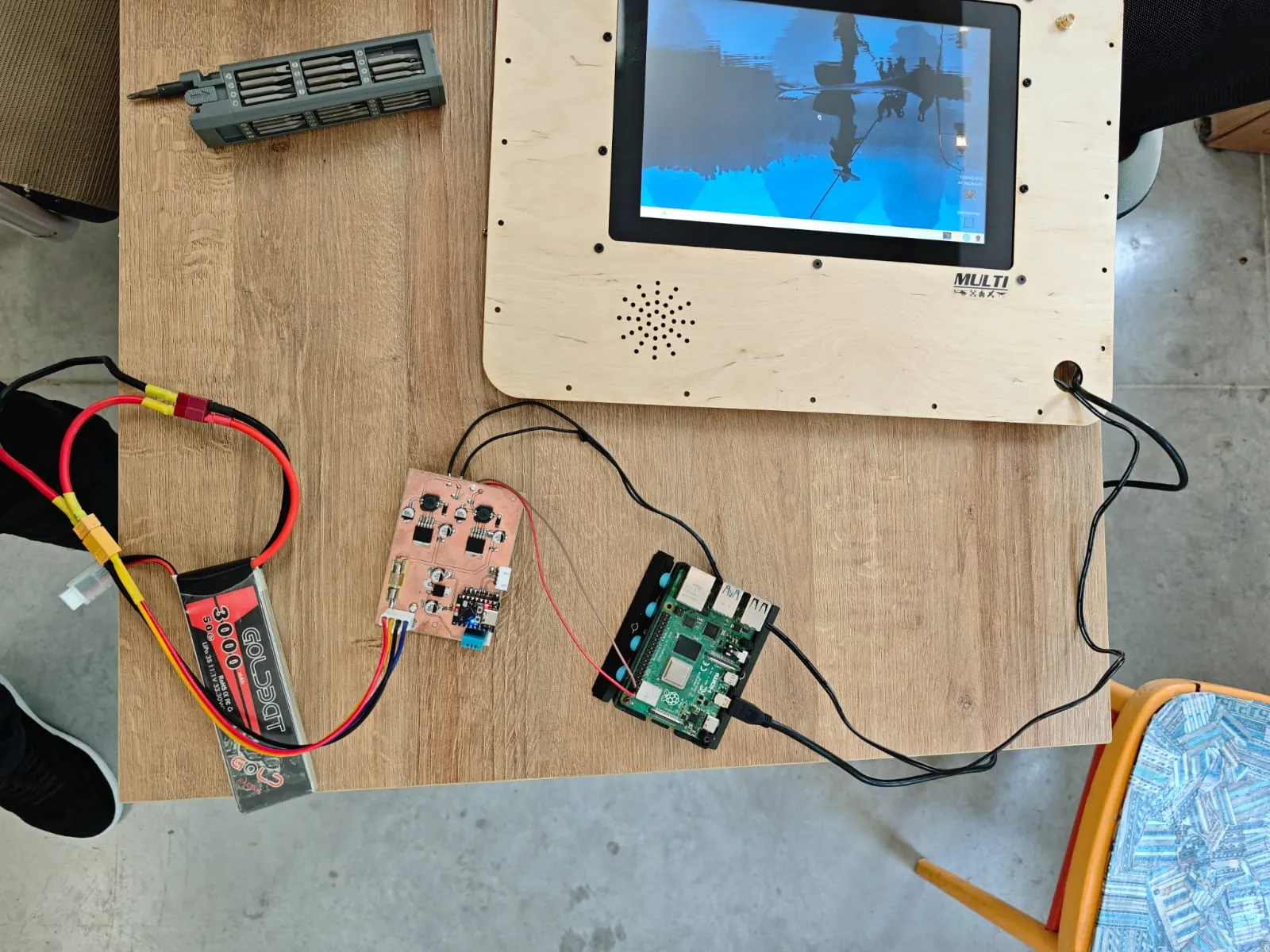
This week I worked on electronics production by manufacturing and testing my custom PMB board.
The board is part of my final project — a Portable Ground Control Station (GCS).
The main goal of this board is to distribute and regulate power for the main GCS components.
Custom PMB for Portable GCS
For my final project I needed a custom Power Management Board.
The board takes 12V input and generates stable 5V outputs for:
- Raspberry Pi
- Display / monitor
- ESP32-S3 controller
- Additional 5V output port
The ESP32-S3 is used to monitor the system and read sensors such as temperature and battery voltage.
Schematic Design
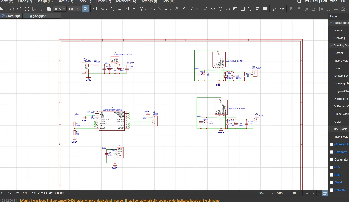
I designed the schematic in EasyEDA.
The board includes:
- 12V input connector
- Fuse protection
- LM2576 buck regulators
- ESP32-S3 module
- DHT11 temperature sensor
- OLED connector
- Voltage divider for battery voltage measurement
- 5V output connectors
PCB Layout
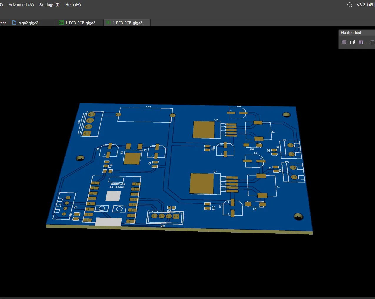
After finishing the schematic, I routed the PCB.
Because this board handles power, I used wider traces for the 12V and 5V power lines.
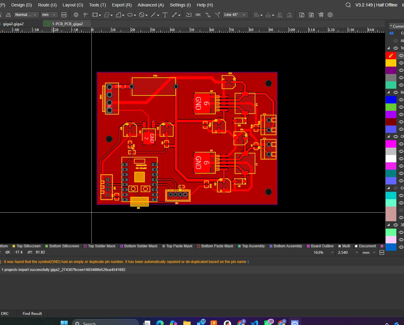
3D Preview
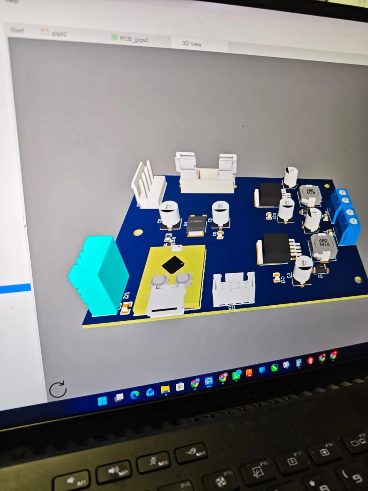
Before fabrication, I checked the board in 3D view to confirm the component placement, connector orientation, and general board layout.
PCB Milling
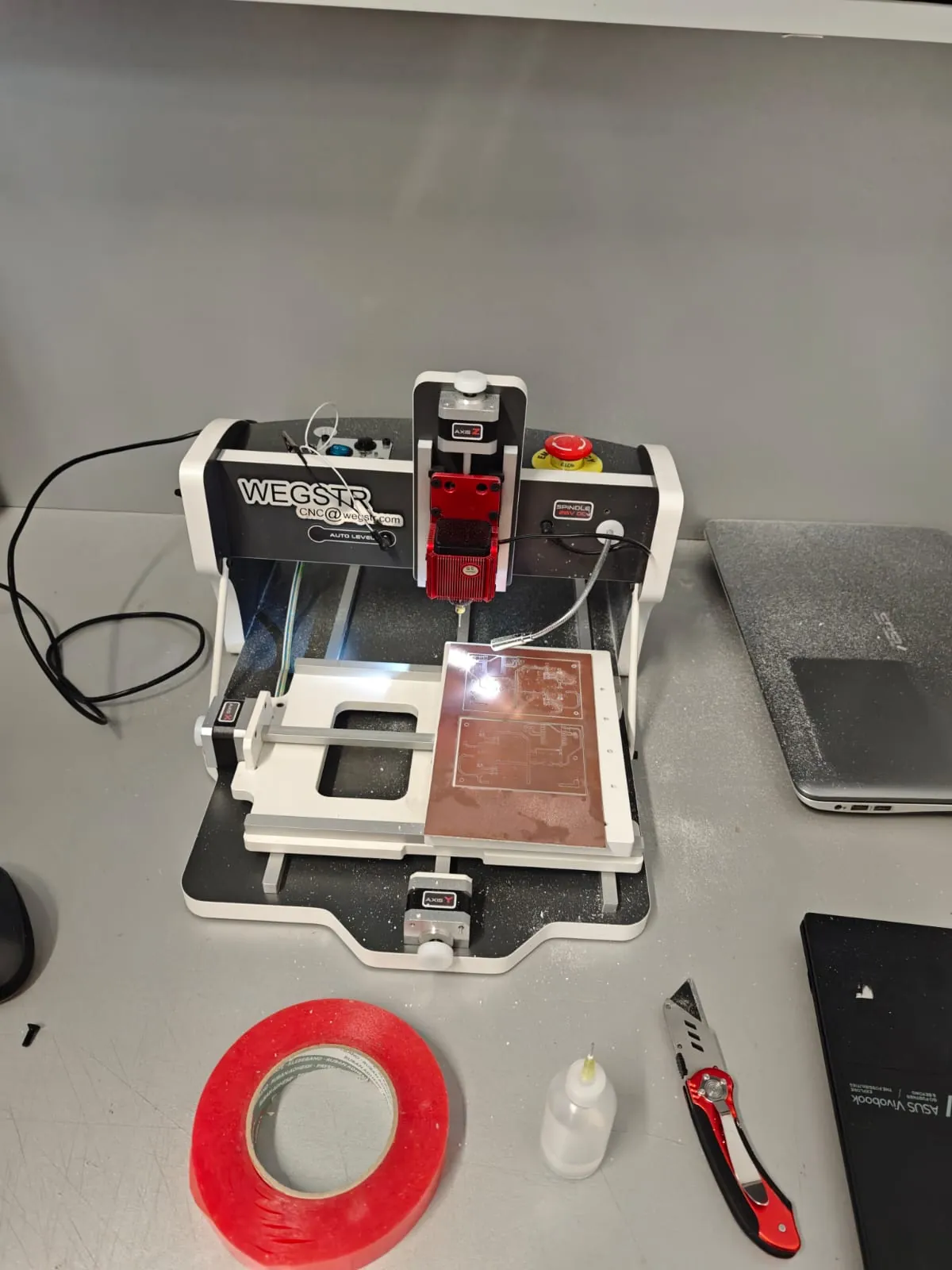
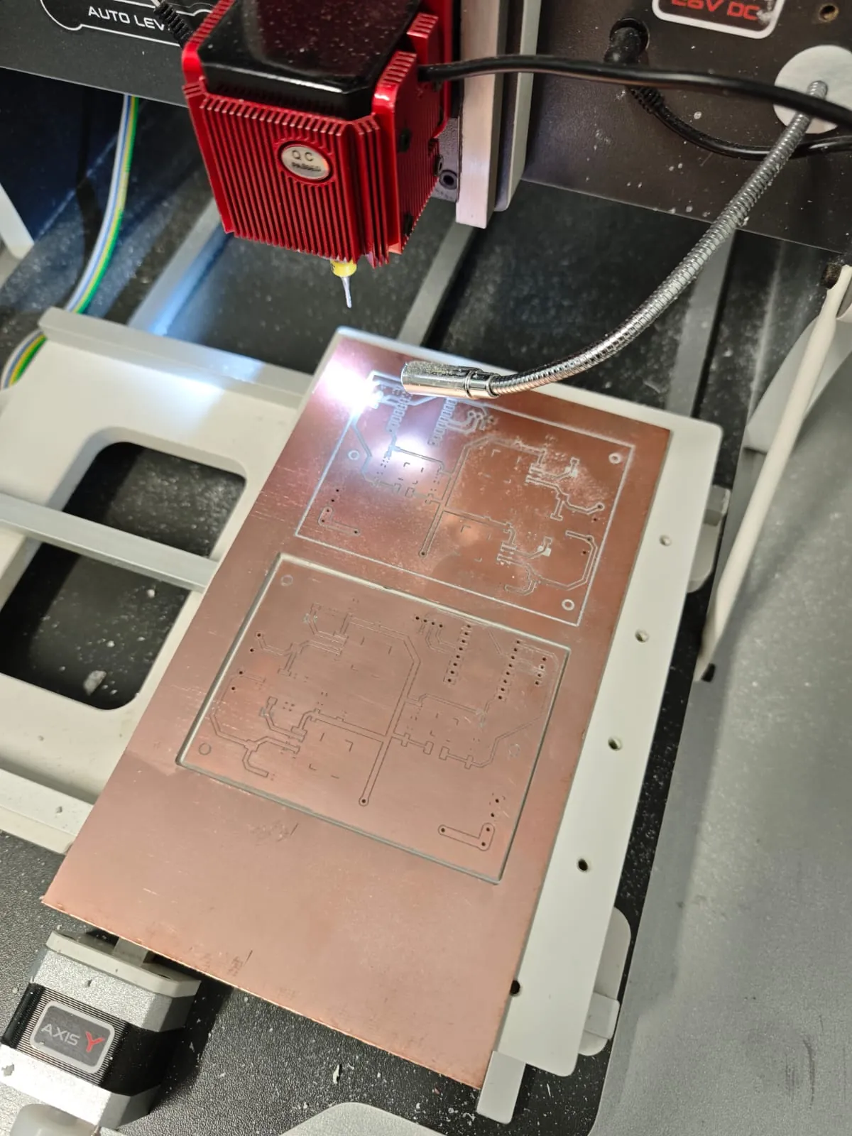
For PCB production I used the WEGSTR CNC machine.
The copper board was fixed on the machine bed and the toolpath was prepared for isolation milling.
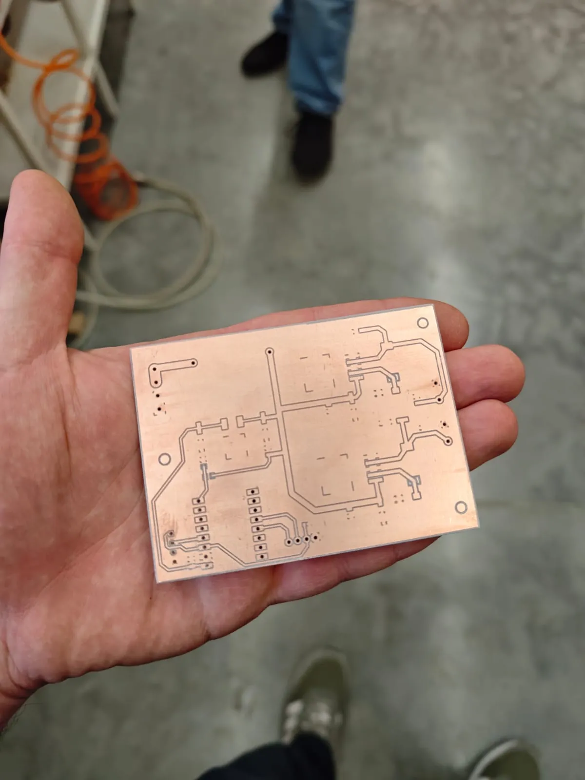
Board After Milling
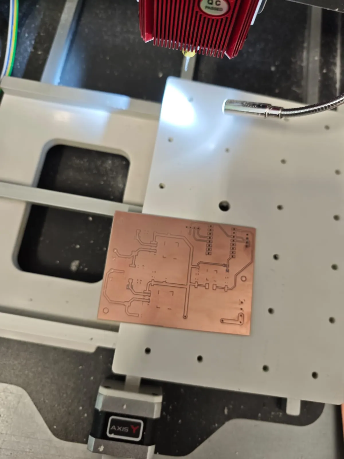
After milling, I removed the board and visually checked the traces.
I also checked if the isolation between traces was clean.
Soldering
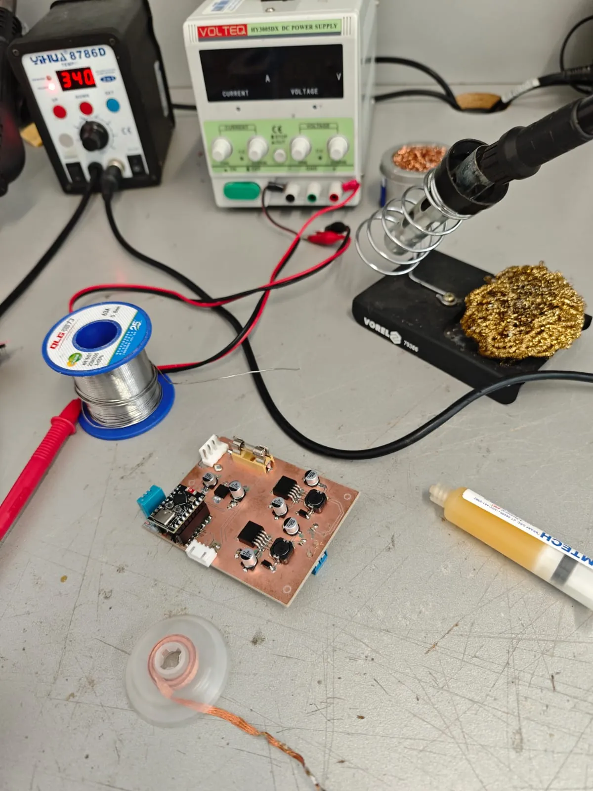
After the PCB was ready, I soldered the components manually.
I started with smaller SMD components and then soldered larger parts like connectors, fuse holder, inductors, capacitors, and the ESP32-S3 module.
Testing
First, I tested the board with a bench power supply.
The input voltage was set to around 12V.
The board successfully generated around 5V output.
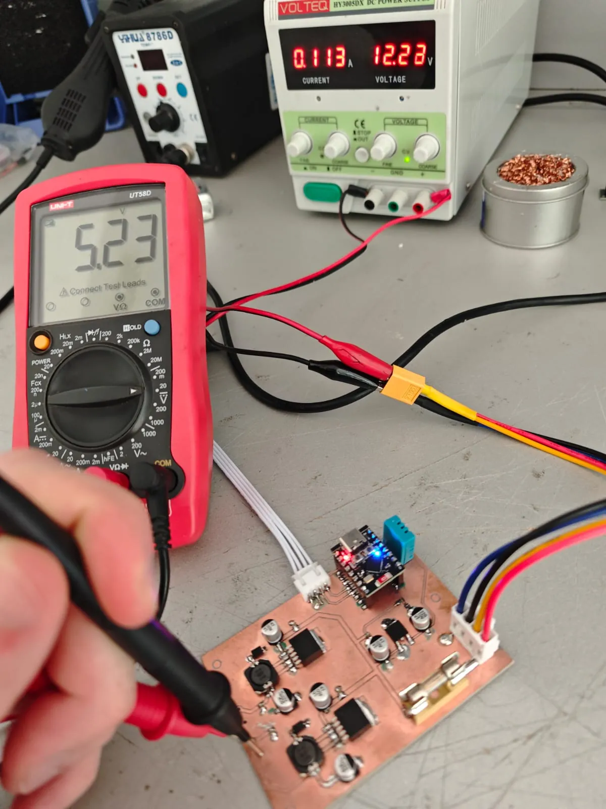
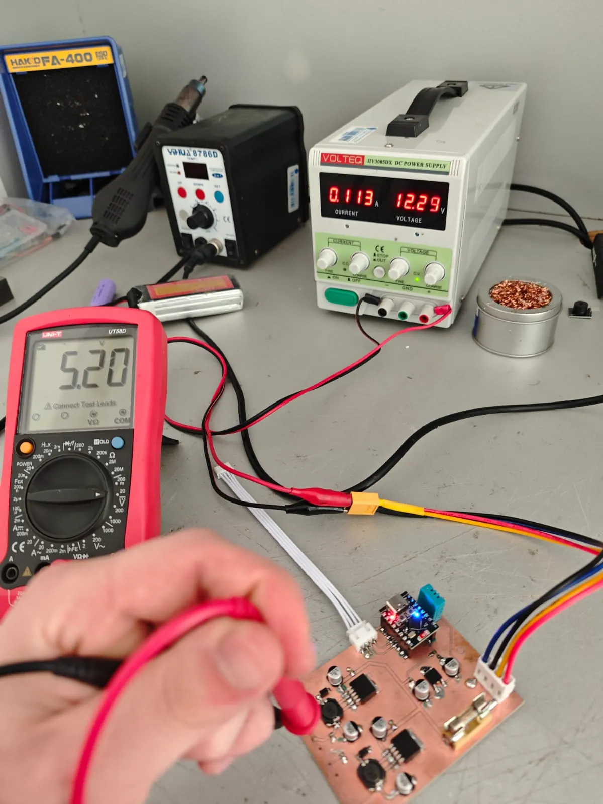
The measured output voltage was approximately 5.2V, which is suitable for powering the Raspberry Pi, display, and ESP32 module.
Result
The custom PMB board was successfully manufactured, soldered, and tested.
It will be used inside my Portable GCS final project as the main power distribution and monitoring board.