Week 05 — Group Assignment
3D Printer Characterization
Objective
The goal of this group assignment was to characterize our 3D printers by testing:
- Nozzle temperature behavior
- Maximum volumetric flowrate limits
We used OrcaSlicer calibration models to evaluate print quality under different parameters.
Printers Used
| Student | Printer | Nozzle | Slicer |
|---|---|---|---|
| Giga | Bambu Lab X1 Carbon | 0.4 mm | OrcaSlicer |
| Dato | Anycubic Vyper | 0.4 mm | OrcaSlicer |
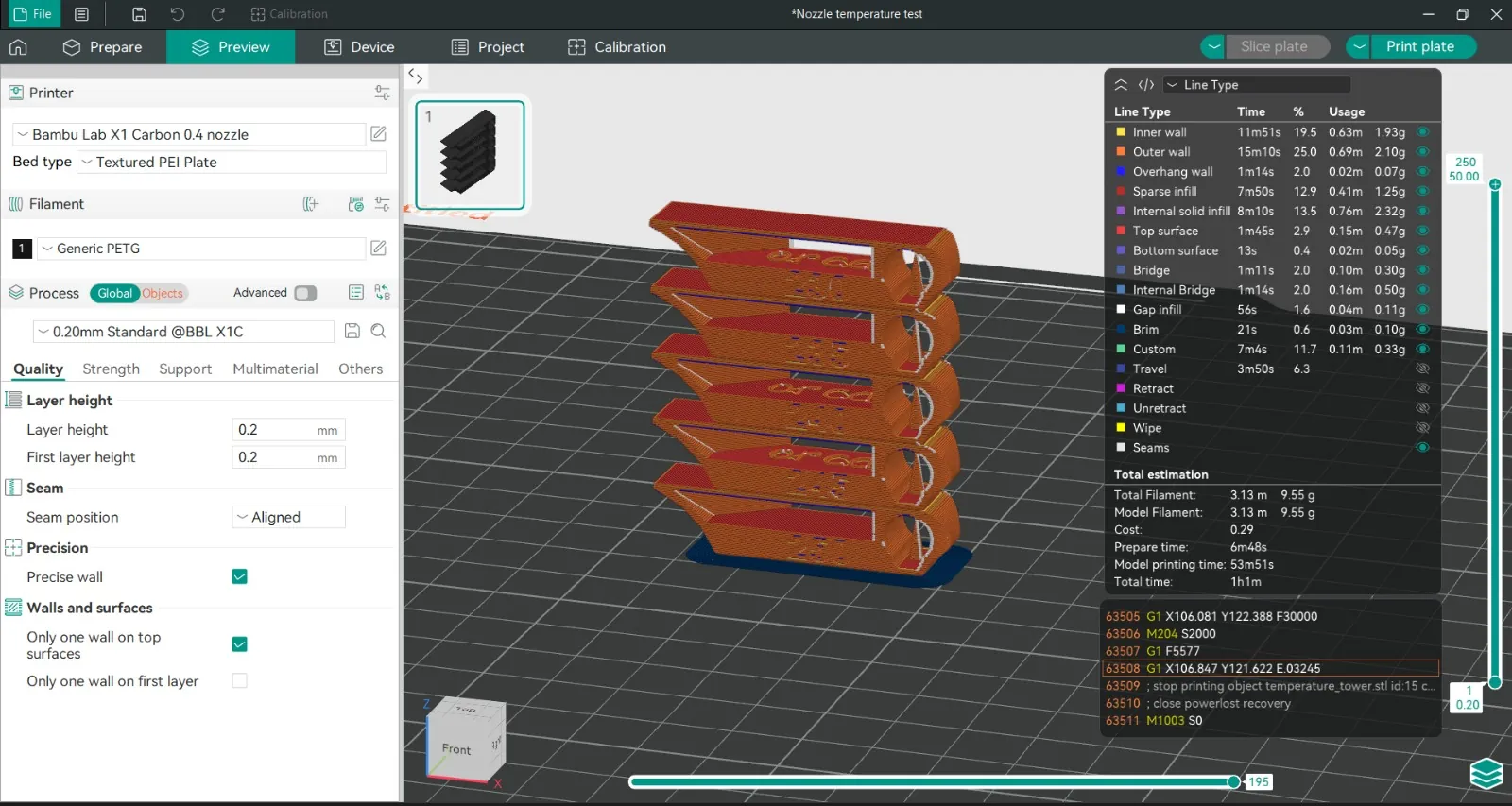
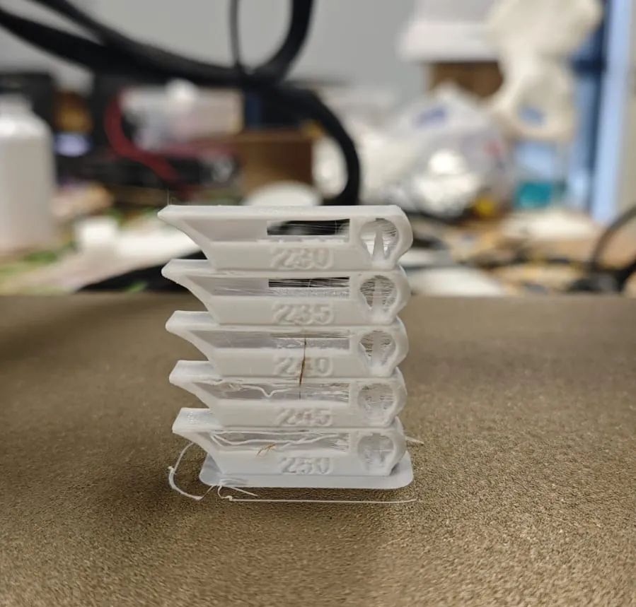
Test 1 — Temperature Tower (PETG)
Goal
Determine optimal PETG temperature using a stepped temperature tower.
Material & Settings
- Filament: Generic PETG
- Nozzle: 0.4 mm
- Layer height: 0.20 mm
- Bed: Textured PEI Plate
- Slicer: OrcaSlicer → Calibration → Temperature Tower
Slicer Preview
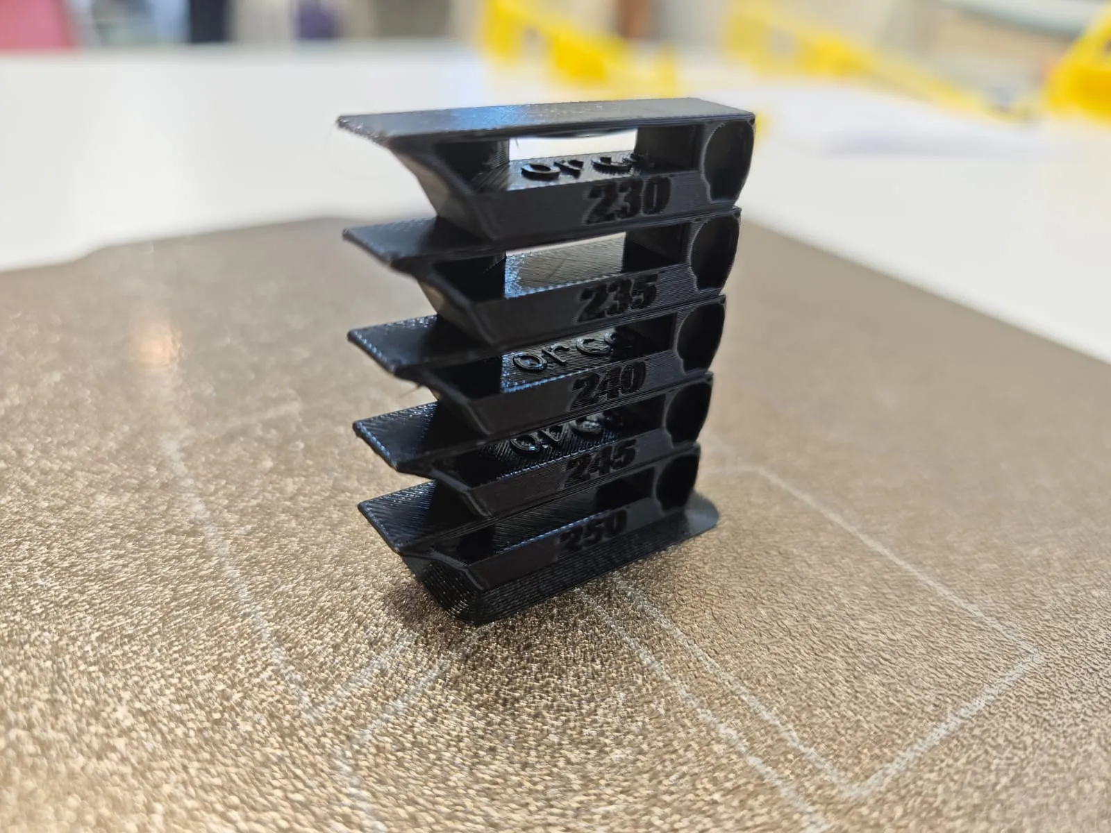
🔍 Printed Results — Temperature Tower
Bambu Lab X1 Carbon — Real Print
Anycubic Vyper — Real Print
Observations
Surface Quality
- Bambu:
- Vyper:
Stringing
- Bambu:
- Vyper:
Layer Adhesion
- Bambu:
- Vyper:
Best Temperature
- Bambu:
- Vyper:
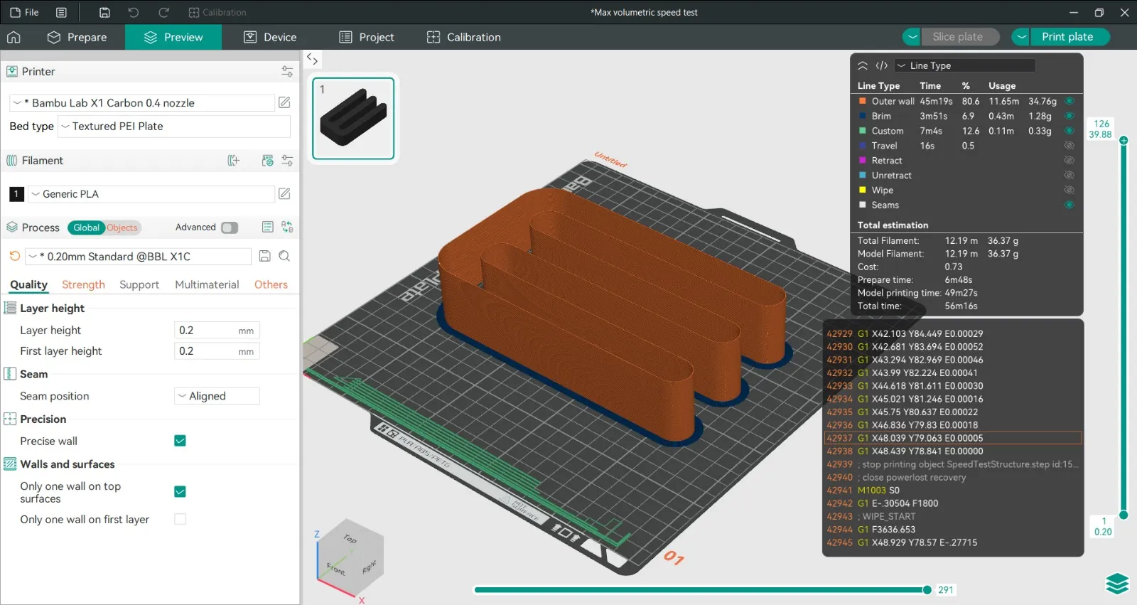
Test 2 — Flowrate / Max Volumetric Speed (PLA)
Goal
Determine maximum stable extrusion rate before defects appear.
Material & Settings
- Filament: Generic PLA
- Nozzle: 0.4 mm
- Layer height: 0.20 mm
- Slicer: OrcaSlicer → Calibration → Max Volumetric Speed
Slicer Preview
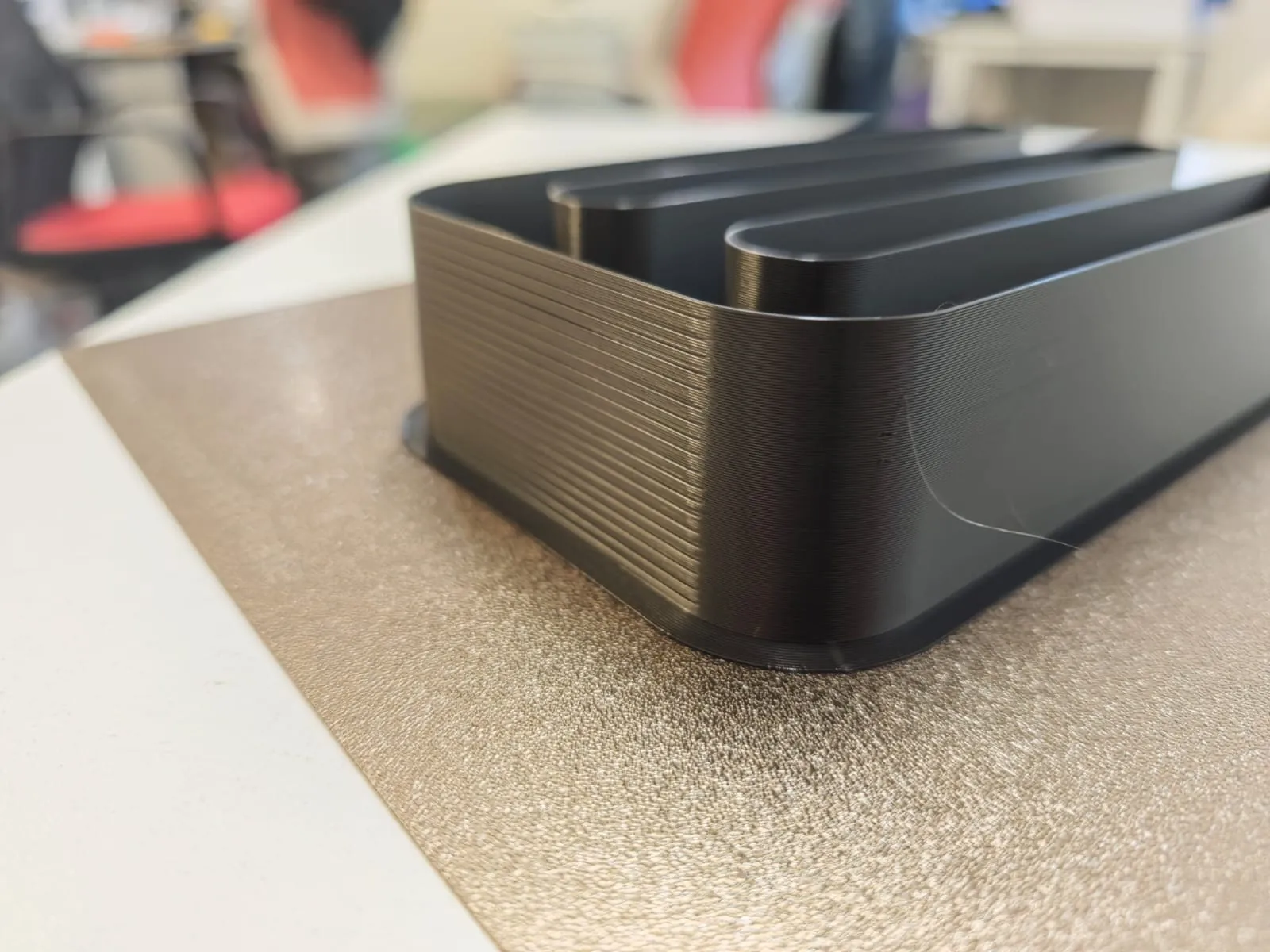
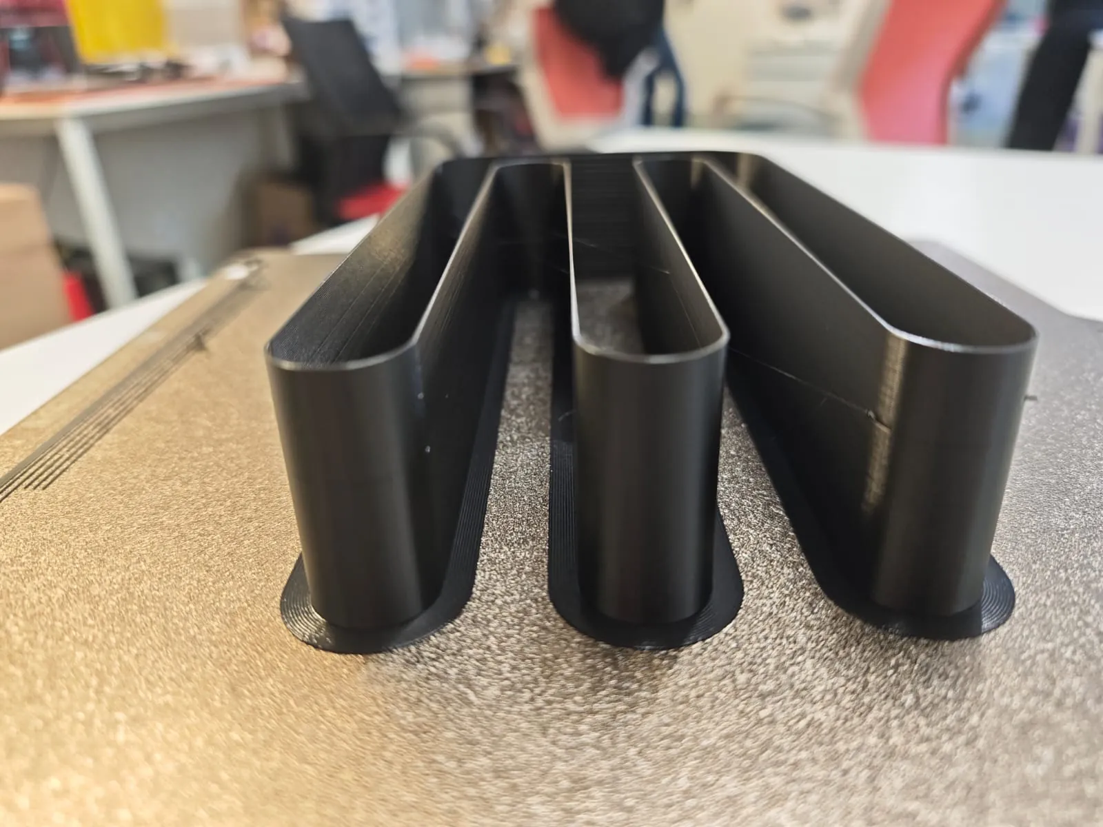
🔍 Printed Results — Flowrate Test
Bambu Lab X1 Carbon — Real Print
Anycubic Vyper — Real Print
Observations
Surface Consistency
- Bambu:
- Vyper:
Under-Extrusion Appearance
- Bambu:
- Vyper:
Maximum Stable Flowrate
- Bambu:
- Vyper:
Comparison Summary
| Parameter | Bambu Lab X1C | Anycubic Vyper |
|---|---|---|
| Optimal PETG Temp | ||
| Stable PLA Flowrate | ||
| Surface Finish | ||
| High Speed Stability |
Week 05 — Individual Assignment
3D Design & Printing — Adjustable Drone Camera Mount
Project Description
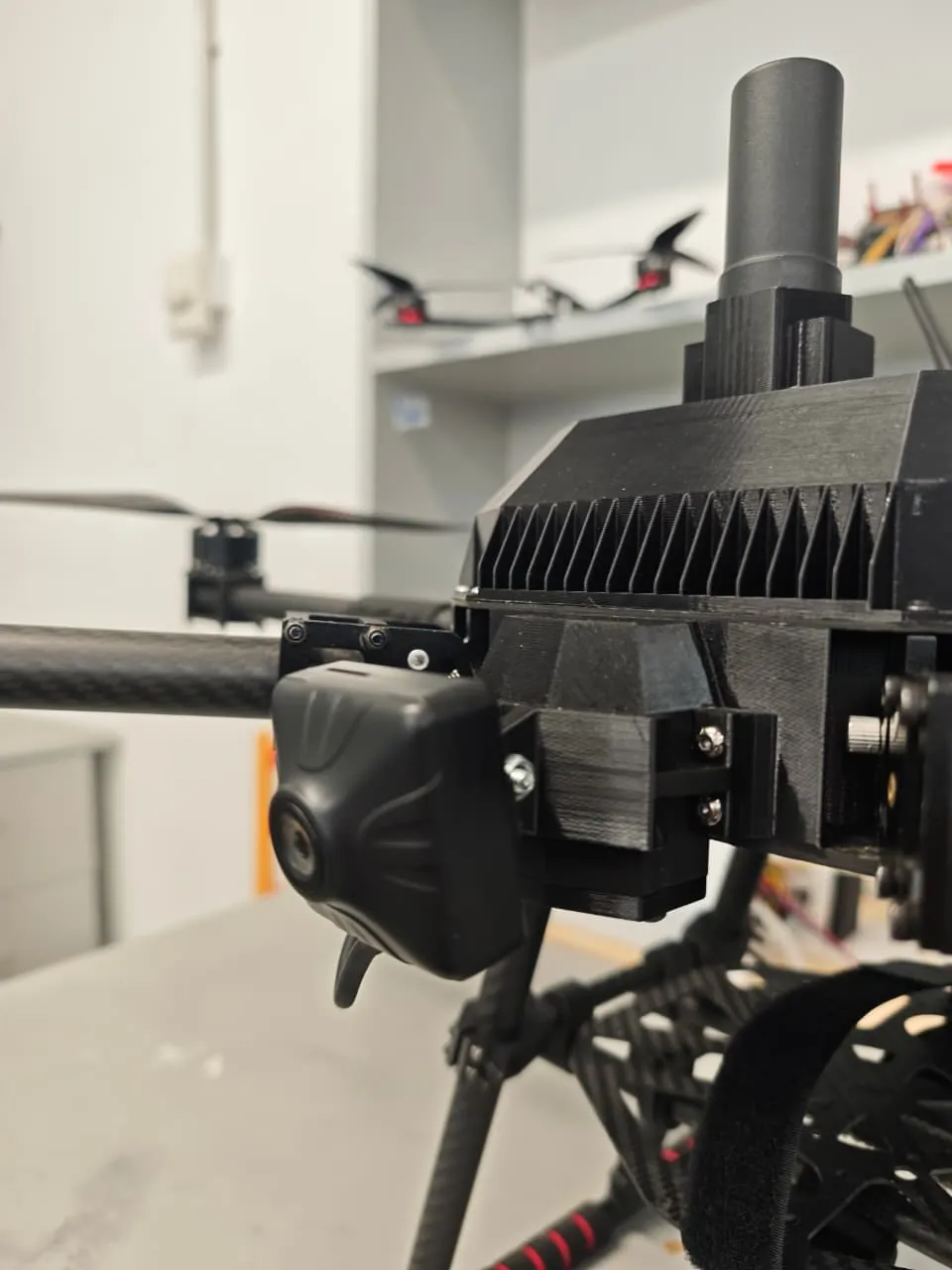
For the individual assignment, I designed and 3D printed an adjustable camera mount for my drone.
The mount is designed specifically for the SIYI FPV camera and allows adjustable tilt angle.
The objective was to create a lightweight, strong, and easily assembled mount suitable for aerial filming and inspection.
Hardware Used
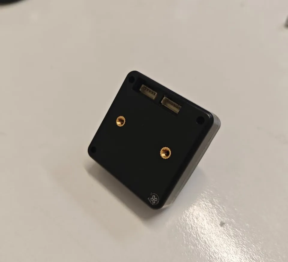
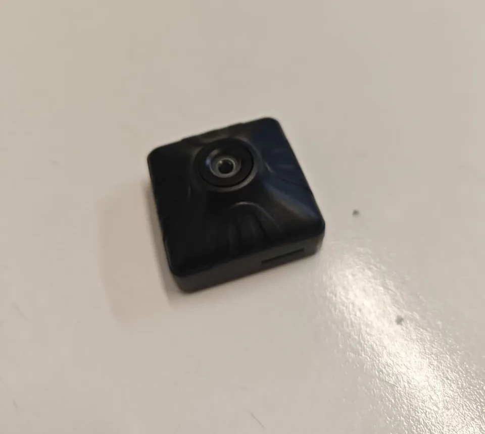
- Camera: SIYI FPV Camera
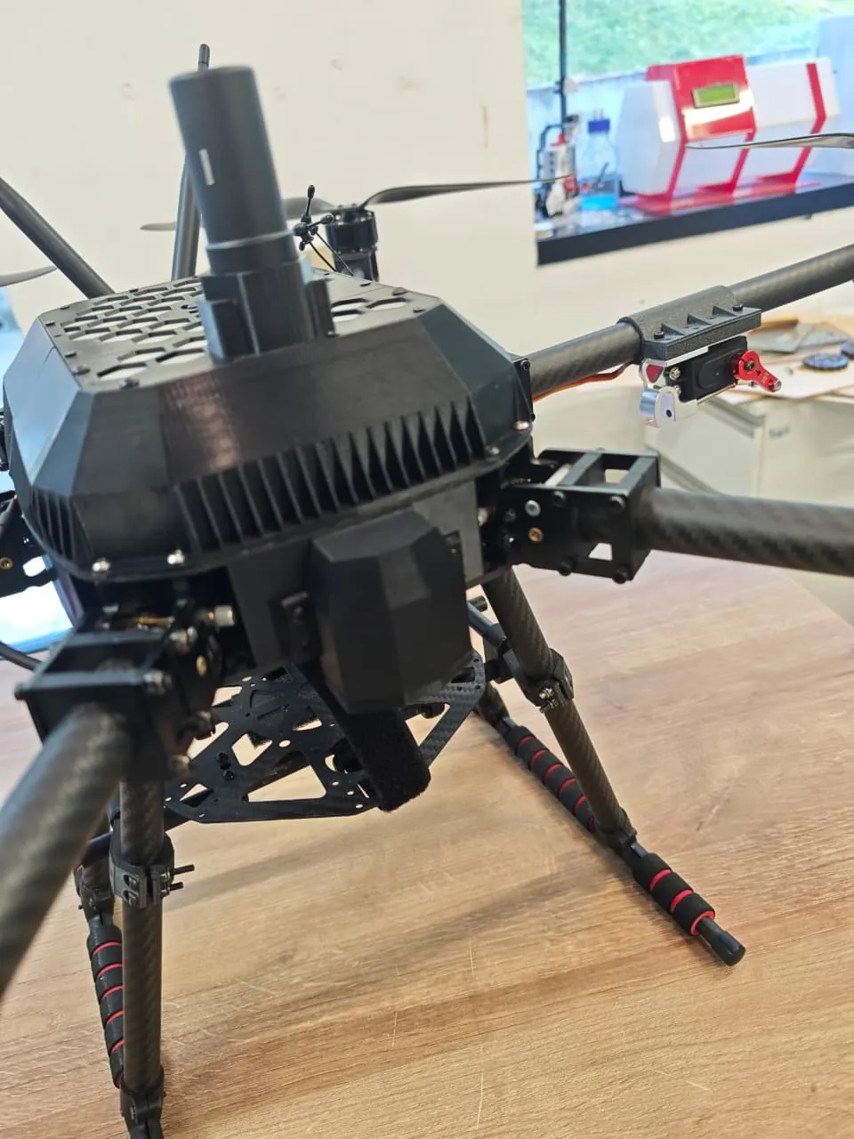
- Drone: Custom multirotor platform
- Fasteners: M4 bolts and hex nuts
- Printer: Bambu Lab X1 Carbon
- Slicer: BambuClicer
- CAD Software: Fusion 360
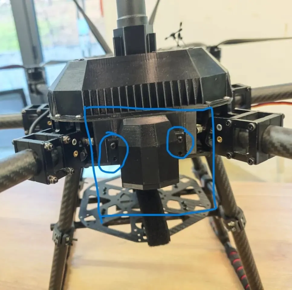
Reference Setup
Drone Mounting Area
Camera Reference
Design Process in Fusion 360
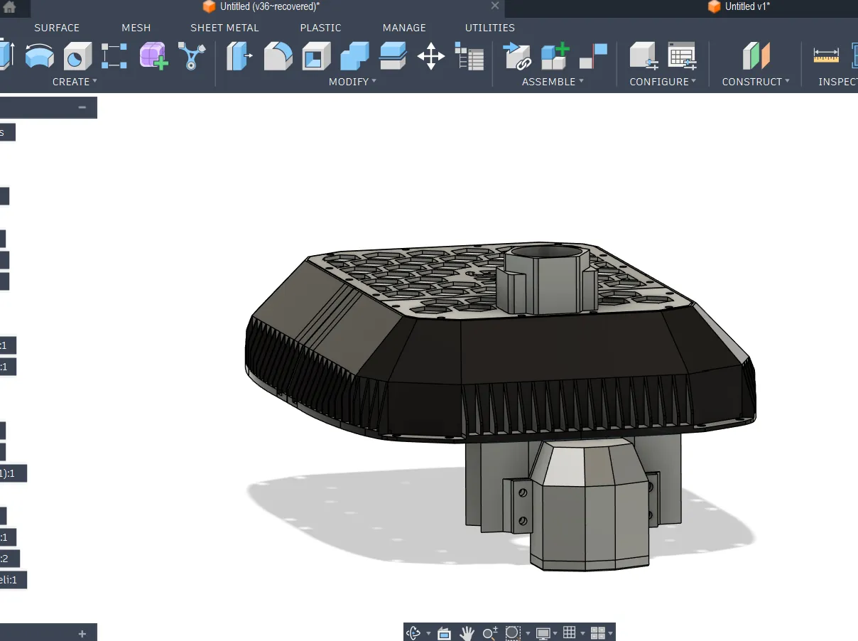
1️⃣ Importing Drone Front Panel
I already had the full drone CAD model, so I imported the front panel part into a new design file.
This helped me:
- Align the camera mount correctly
- Match hole spacing
- Check clearances with frame parts
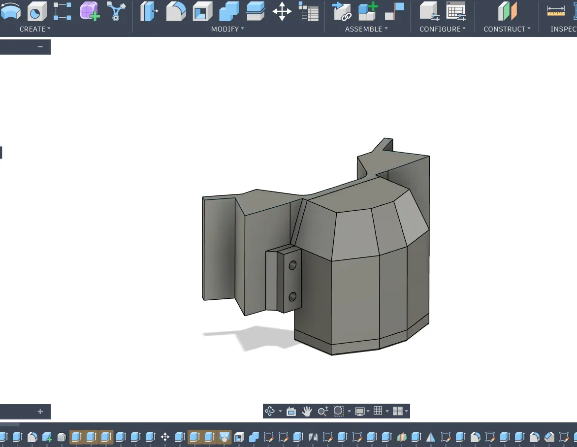
2️⃣ Designing the Base Mount
I created the base mount that attaches directly to the drone front panel.
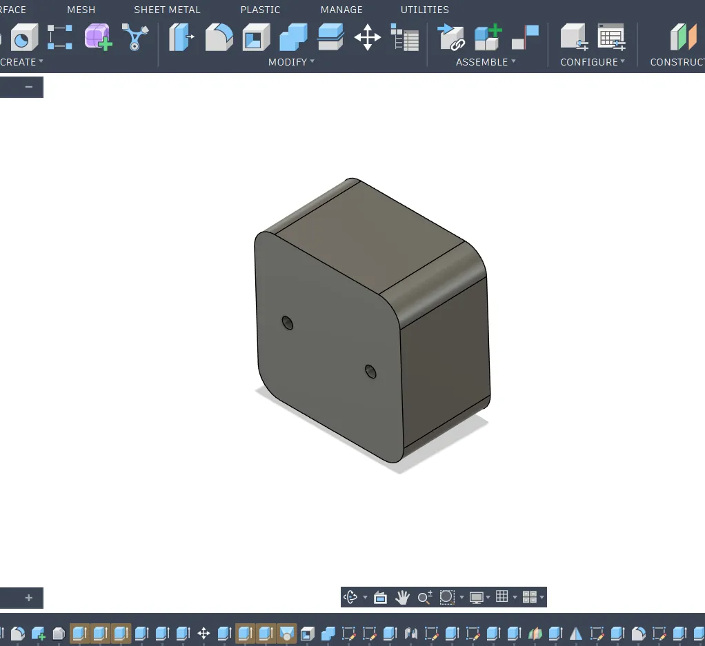
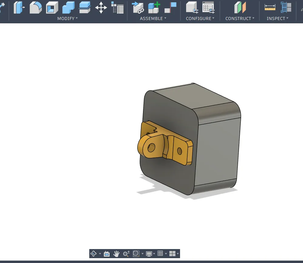
3️⃣ Creating a Simple Camera Model
Before designing the holder, I built a simplified model of the SIYI FPV camera.
This model included:
- Main body dimensions
- Mounting hole positions
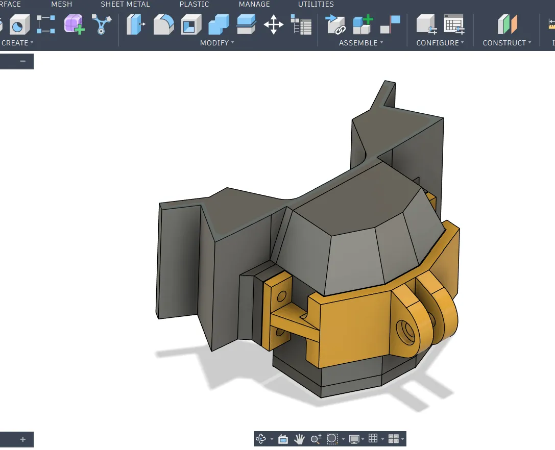
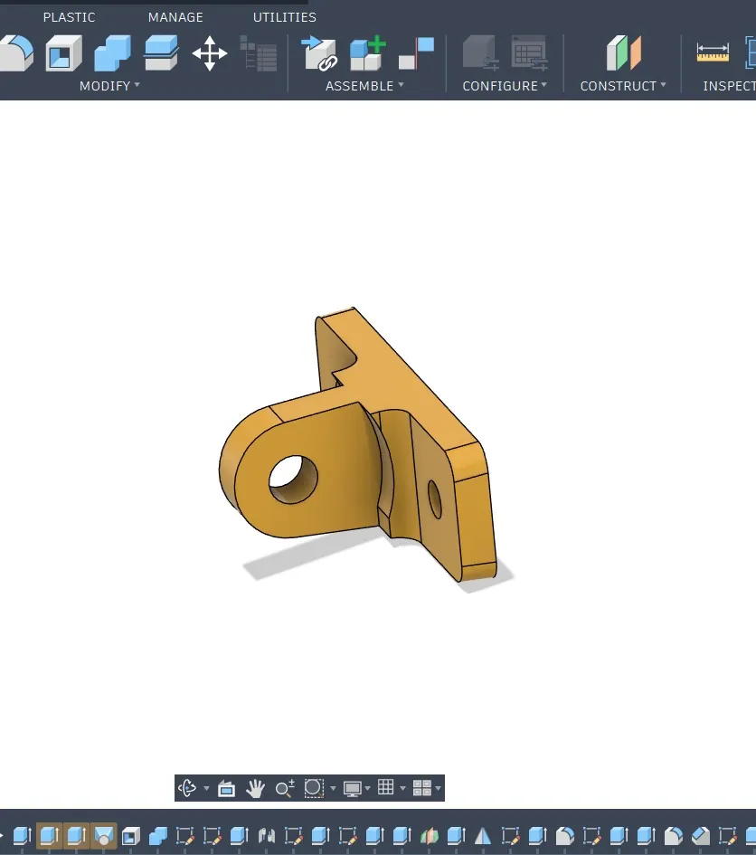
4️⃣ Designing the Adjustable Holder
I then designed the camera holder.
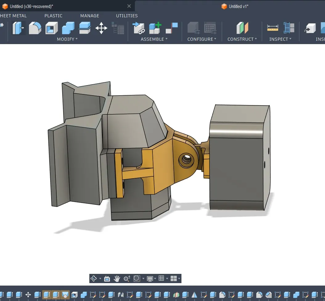
5️⃣ Assembly in Fusion 360
After modeling both parts:
- Converted bodies into components
- Positioned them together
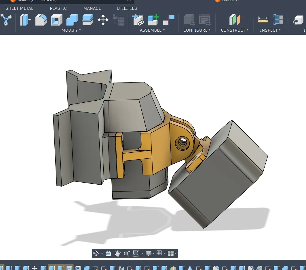
- Applied Revolute Joint
- Tested movement angle
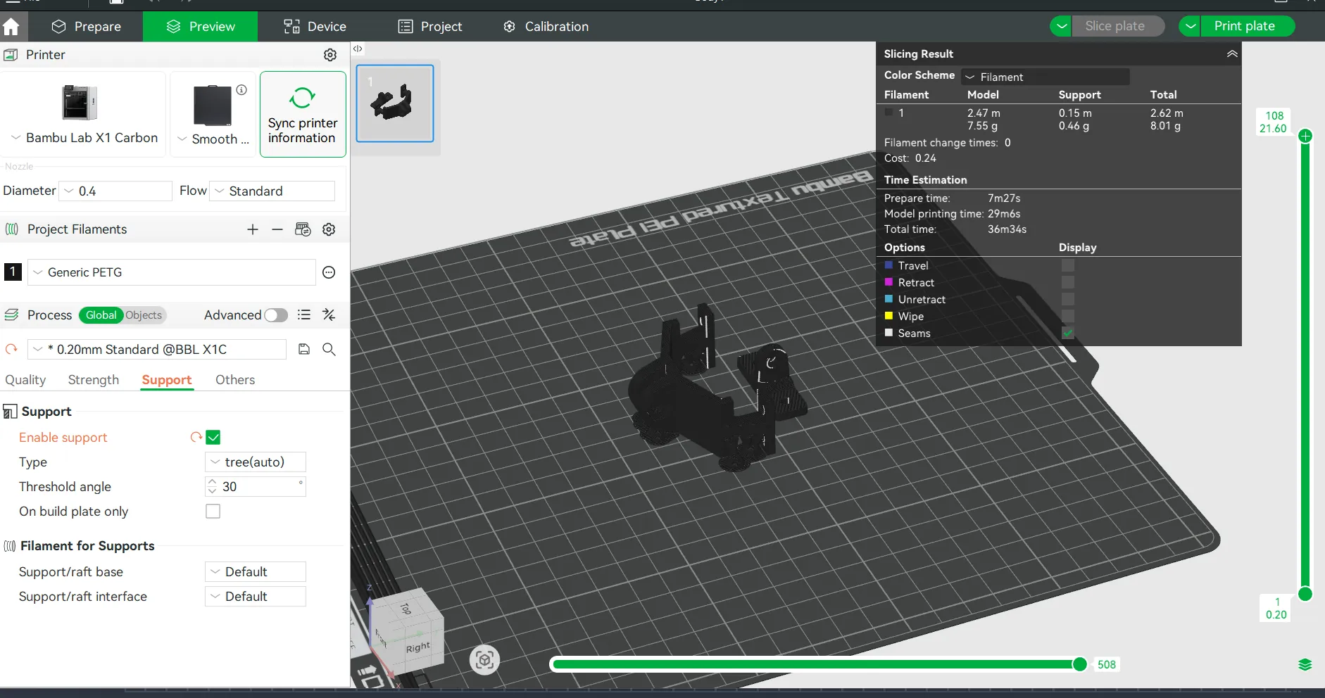
6️⃣ Slicing
I exported both parts as STL and imported them into BambuSlicer.
- Oriented parts
- Checked supports
- Verified layer preview
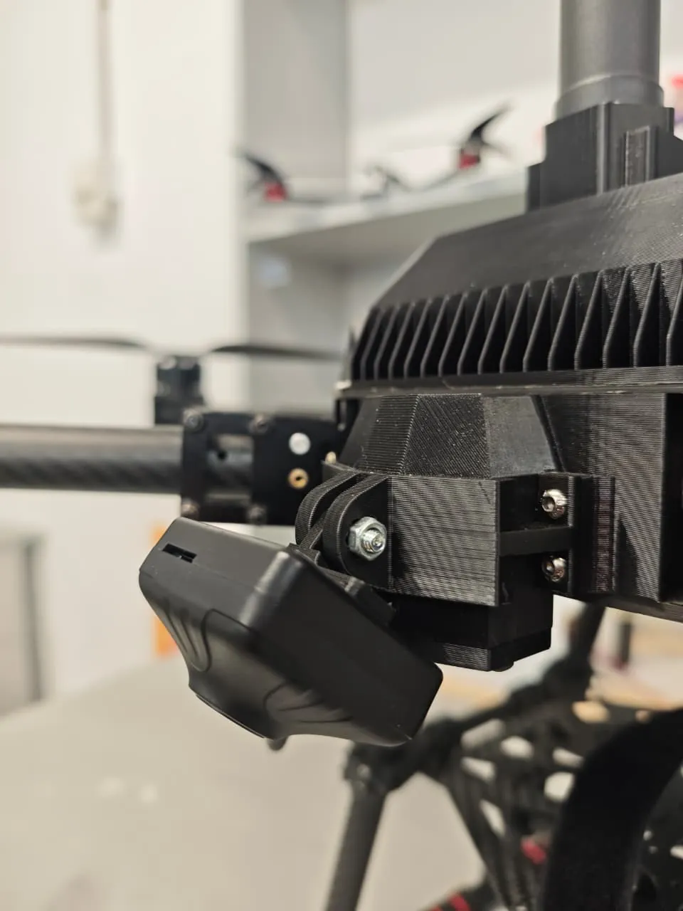
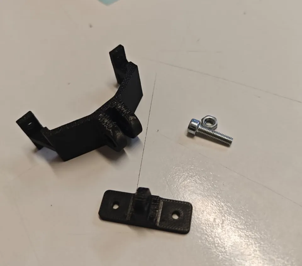
7️⃣ Printing & Assembly
- Printed both parts
- Removed supports
- Installed M4 bolts
- Mounted the camera
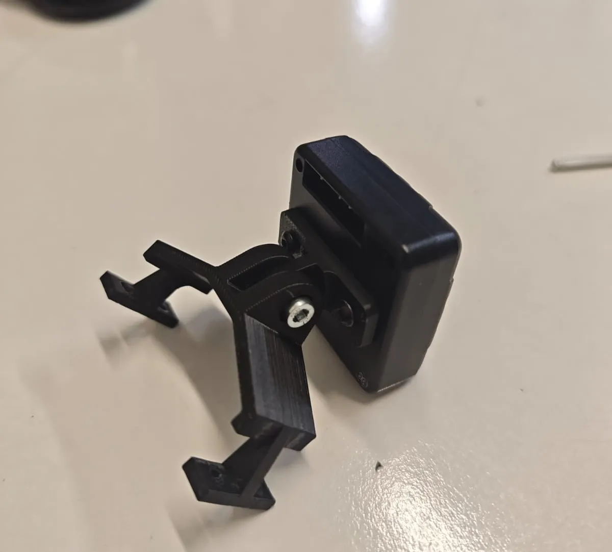
8️⃣ Mounted on Drone
Finally, I attached the mount to the drone.