Week 02 — Computer-Aided Design
Focus this week
I have some experience in Fusion 360, but this week I wanted to:
- learn Joints and Motion tools (to test ideas for my final project)
- understand how linear motion is defined and simulated
- explore OpenSCAD as a code-based parametric CAD tool
- compare traditional CAD (Fusion 360) with script-based modeling (OpenSCAD)
Tools I used
- Fusion 360 (joints, motion, assembly tests)
- OpenSCAD (parametric / code-based modeling)
Part A — Fusion 360 (Linear Actuator, Joints & Motion)
Goal
For my final project I plan to use linear actuators, so this week I focused on:
- building a simple linear actuator model
- understanding how linear motion is defined in Fusion 360
- testing motion limits and constraints
Initial actuator test (components vs bodies)
First, I built a simple two-part model that connects and moves relative to each other.
Instead of modeling everything as bodies, I created separate components.
This is important because joints in Fusion 360 only work between components, not bodies.
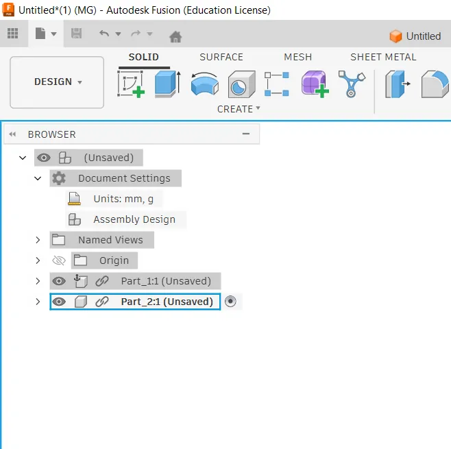
Creating separate components
Model building process
I started by creating a 2D sketch on the base plane.
- Drew simple geometry using rectangle and line tools
- Applied dimensions to control size
- Used constraints to keep the sketch stable
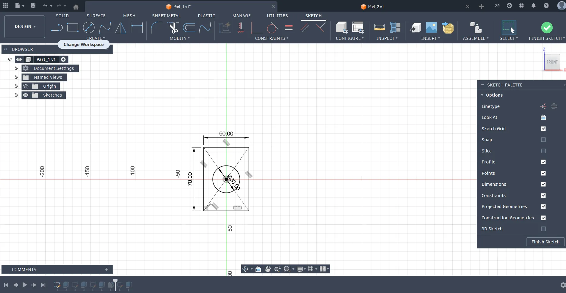
Base sketch for first component
Then I converted the sketch into a 3D model using the Extrude tool.
- Defined thickness of the part
- Repeated the same process for the second part
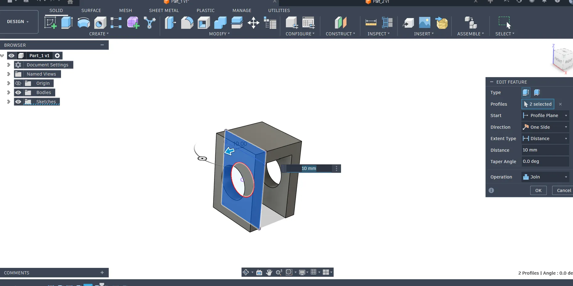
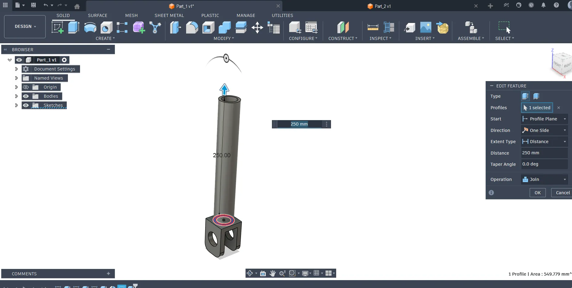
Extruding sketch into 3D body
Simple component connection test
After that, I positioned the two components and prepared them for motion testing.
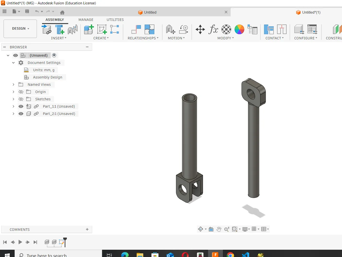
Two simple parts prepared for connection
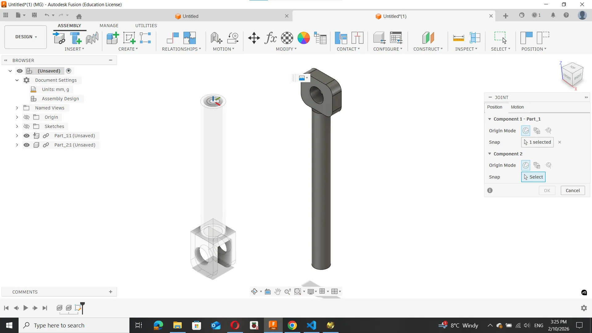
Next, I used the Joint tool in Fusion 360.
- Selected both components
- Defined a Slider Joint
- Set the direction of movement
This joint allows motion only along a single axis, simulating a linear actuator mechanism.
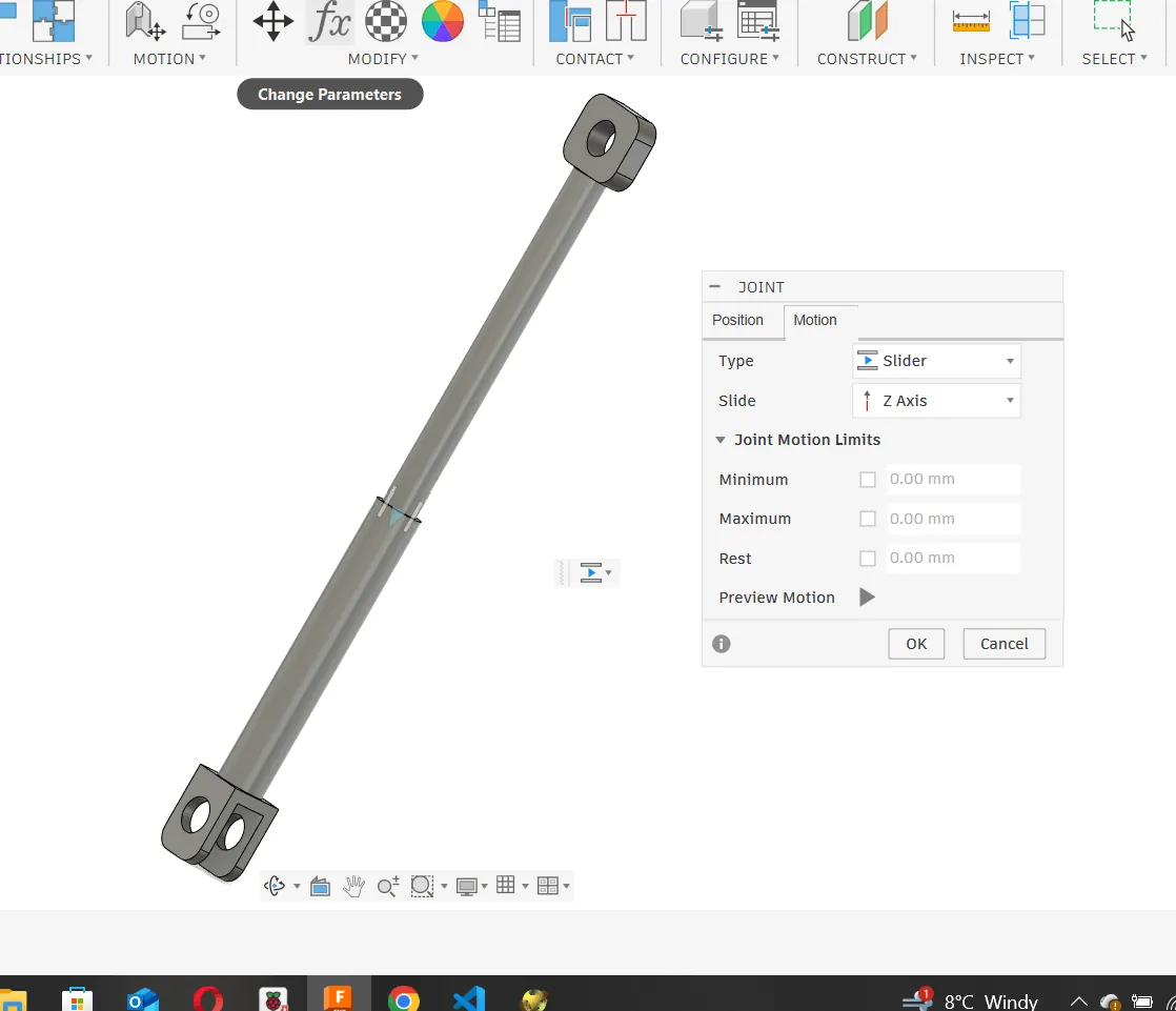
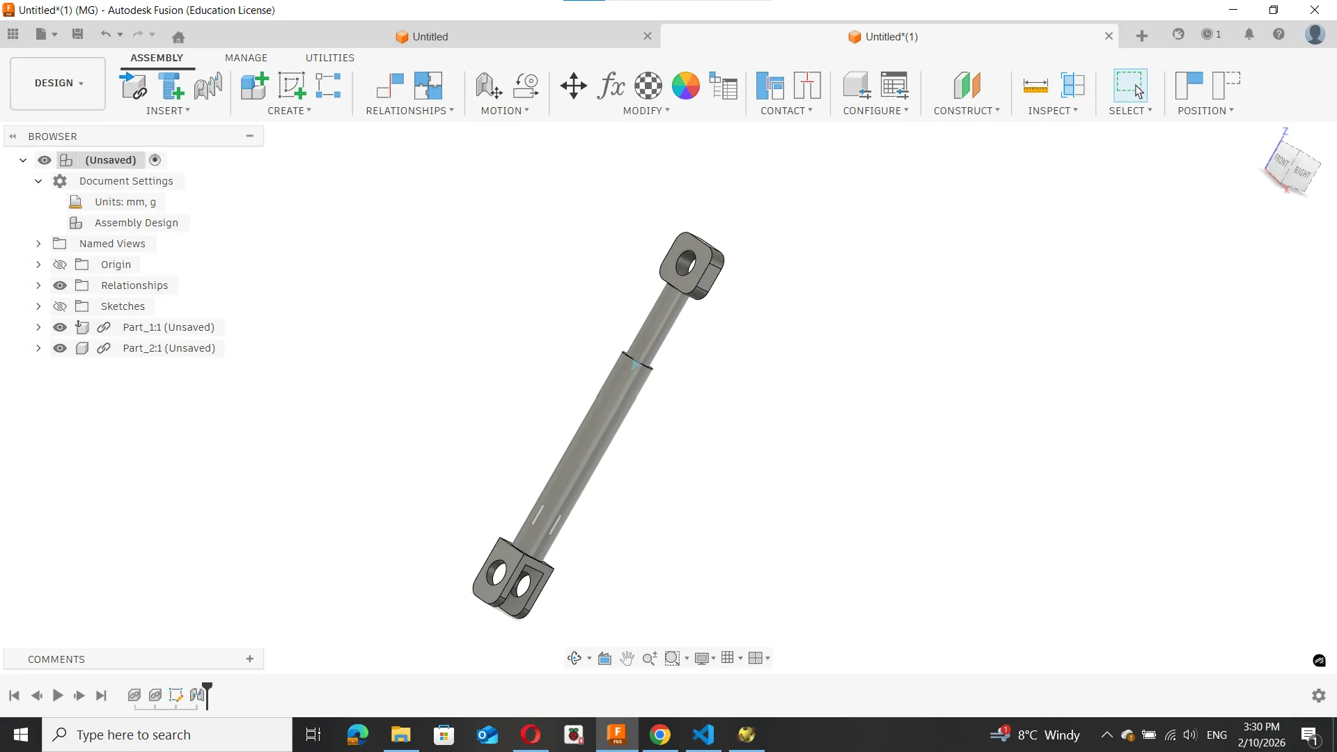
Motion testing and observations
After applying the joint, I tested the movement:
- the components moved smoothly along one axis
- motion depended on proper alignment of joint origins
Motion Test
This helped me understand how constraints define real mechanical behavior in Fusion 360.
Reflection
This simple test helped me understand:
- the importance of using components instead of bodies
- how joints define movement
- how Fusion 360 can simulate real mechanical systems
This will be useful for designing more complex actuator systems in my final project.
Part B — OpenSCAD (Parametric CAD Using Code)
Goal
After working with Fusion 360 and motion tools, I wanted to explore a different CAD approach.
For this purpose, I used OpenSCAD, which is a script-based parametric modeling tool.
The goal was to:
- understand code-based modeling
- compare it with traditional sketch-based CAD
- create a simple parametric mechanical part
- generate fabrication-ready geometry
Why OpenSCAD?
Unlike Fusion 360, OpenSCAD does not use sketches or graphical constraints.
Instead, geometry is defined entirely using code, variables, and logic.
This makes it:
- fully parametric
- very precise and repeatable
- easy to modify by changing a few variables
However, it does not support:
- assemblies
- motion simulation
- joints
OpenSCAD is more suitable for geometric and repeatable parts, rather than complex mechanical assemblies.
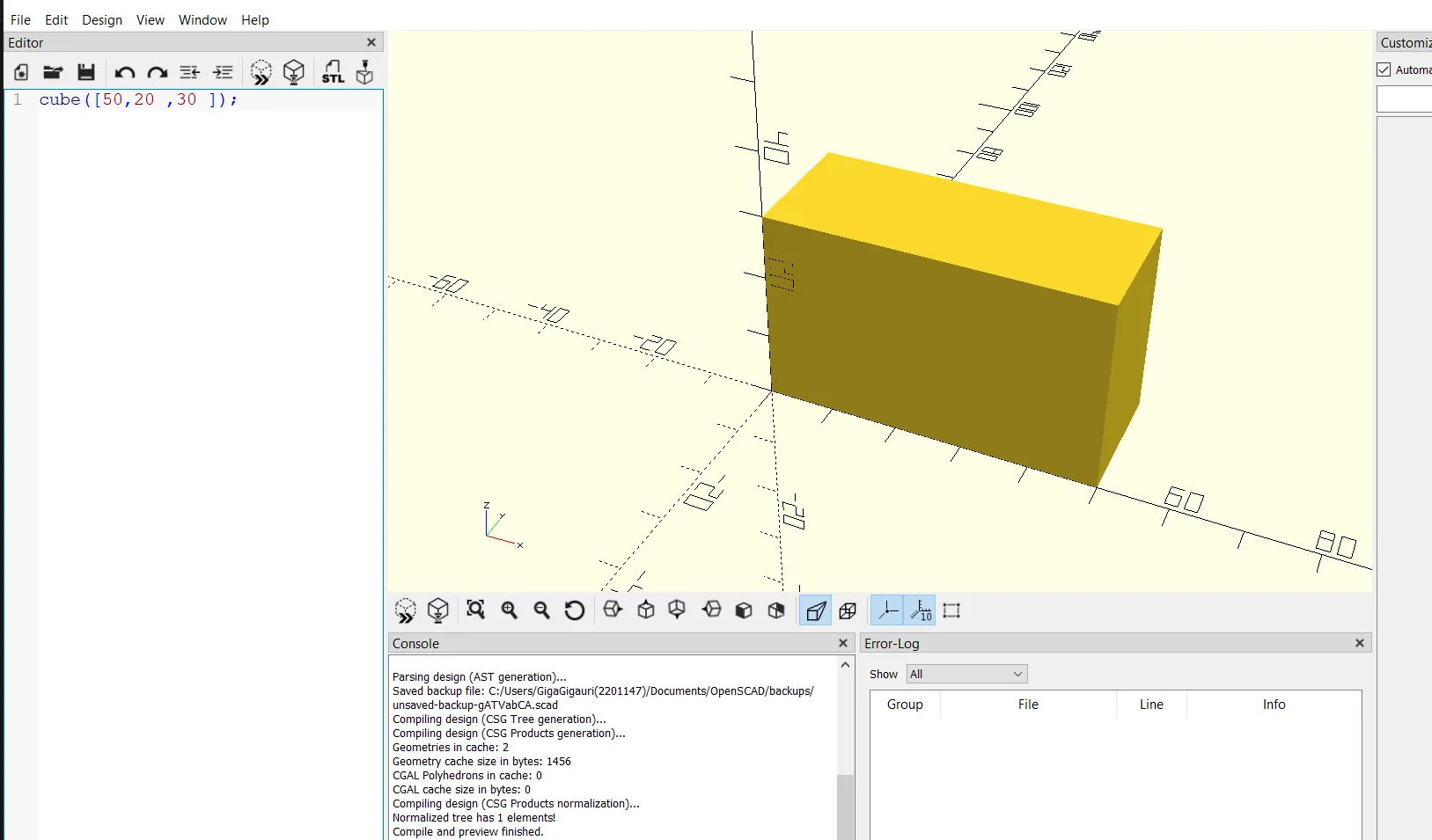
First Parametric Test
To understand the workflow, I created a simple parametric block.
Example code:
length = 50;
width  = 20;
height = 30;

cube([length, width, height]);
By changing the values of length, width, or height, the model updates instantly.
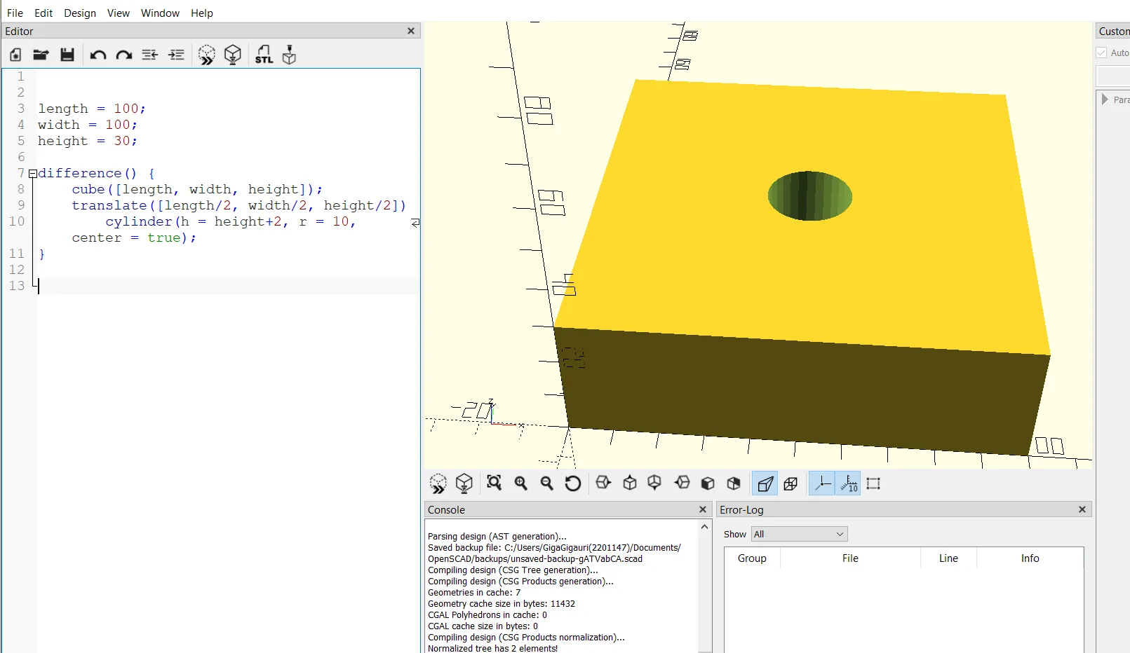
Adding Features (Boolean Operations)
Next, I modified the model by subtracting a hole using the difference() function.
difference() {
    cube([60, 20, 10]);

    translate([30, 10, 5])
        cylinder(d = 8, h = 20, center = true);
}
This introduces the concept of boolean operations, which are fundamental in OpenSCAD:
union()→ combine shapesdifference()→ subtract geometryintersection()→ keep overlapping volume
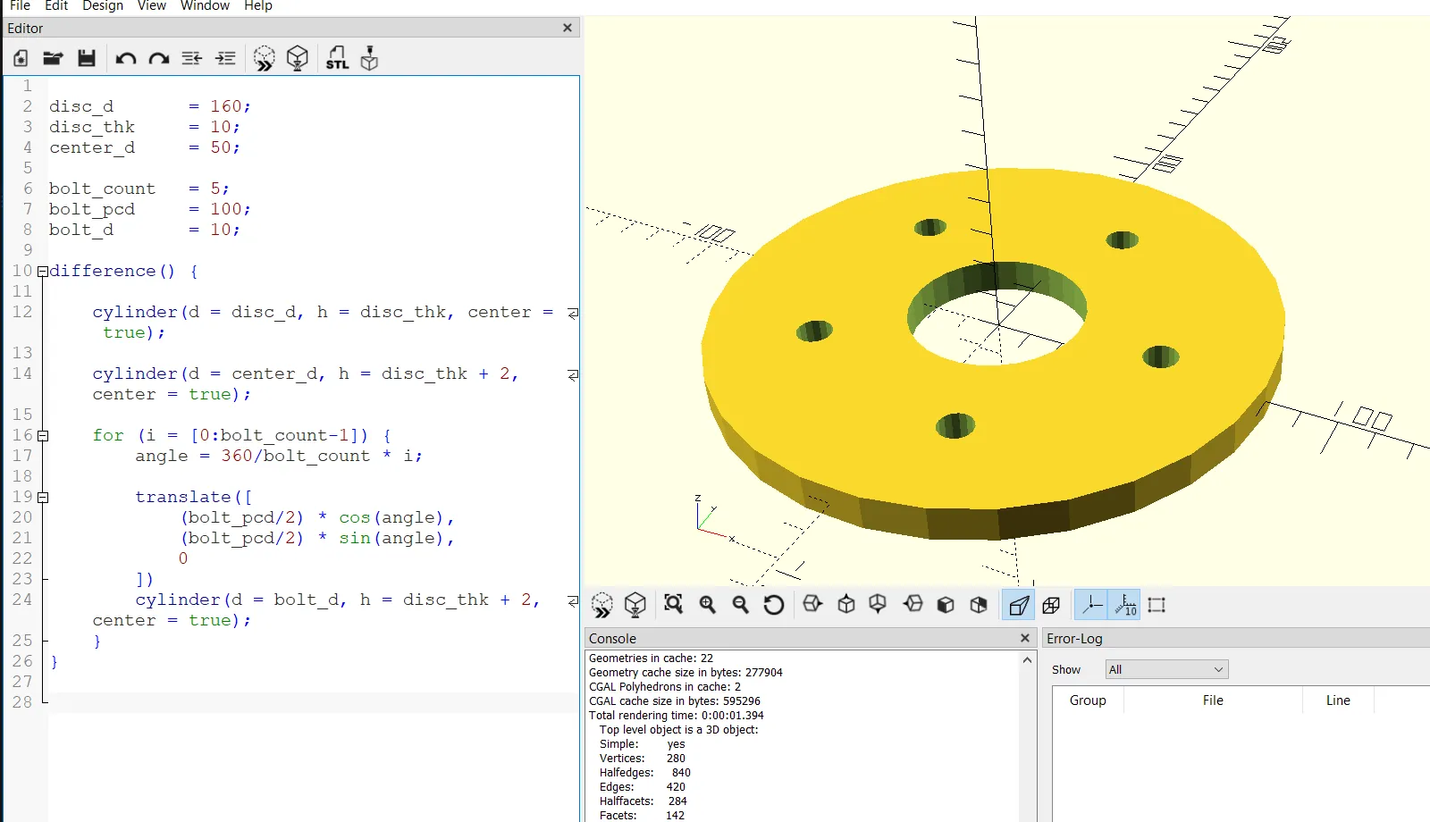
Simple Disc Geometry in OpenSCAD
To build a more realistic mechanical example, I created a parametric disc with bolt holes.
The model consists of:
- one main cylindrical body (disc)
- one center hole
- multiple bolt holes distributed evenly on a circular pattern
Full OpenSCAD Code
// ===== Parameters =====
disc_d    = 160;   // Disc diameter
disc_thk  = 10;    // Thickness
center_d  = 50;    // Center hole diameter

bolt_count = 5;    // Number of bolt holes
bolt_pcd   = 100;  // Bolt circle diameter
bolt_d     = 10;   // Bolt hole diameter

// ===== Main Geometry =====
difference() {

    // Main disc
    cylinder(d = disc_d, h = disc_thk, center = true);

    // Center hole
    cylinder(d = center_d, h = disc_thk + 2, center = true);

    // Bolt hole pattern
    for (i = [0 : bolt_count - 1]) {

        angle = 360 / bolt_count * i;

        translate([
            (bolt_pcd / 2) * cos(angle),
            (bolt_pcd / 2) * sin(angle),
            0
        ])
        cylinder(d = bolt_d, h = disc_thk + 2, center = true);
    }
}
Code Explanation
The model is fully controlled by parameters:
disc_d→ overall disc diameterdisc_thk→ thicknesscenter_d→ central holebolt_count→ number of holesbolt_pcd→ bolt circle diameterbolt_d→ hole size
The difference() function subtracts all holes from the main disc.
A for loop is used to:
- evenly distribute bolt holes
- calculate angular positions
- place holes using
translate()
This makes the model fully parametric and scalable.
Exporting Files
After finishing the model, I exported it as:
- STL file for fabrication
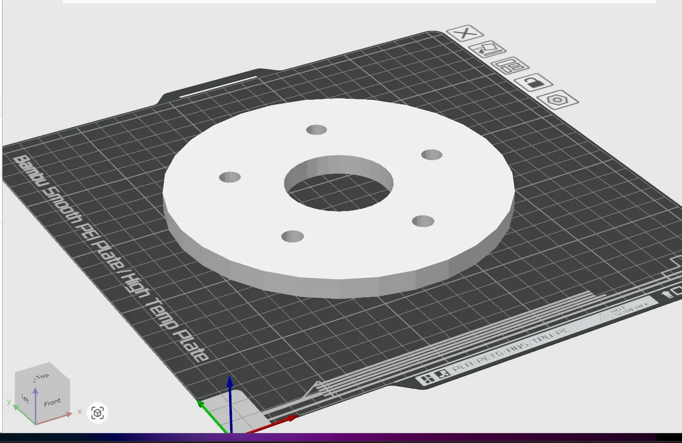
Then I verified the STL in a slicer to confirm:
- correct scale (mm)
- no geometry errors
- clean mesh
Reflection
This exercise demonstrated the difference between visual CAD and code-based modeling.
- Fusion 360 → intuitive, visual, good for assemblies
- OpenSCAD → precise, parametric, ideal for repeatable parts
I found OpenSCAD especially useful for parametric mechanical components where dimensions may need to change frequently.
Image Optimization Workflow
To keep the website lightweight, I used a VS Code extension to compress images and convert them to WebP format.