Electronics Production
For this assignment, we first searched for the materials and components needed to fabricate the board that had been previously designed in KiCad.
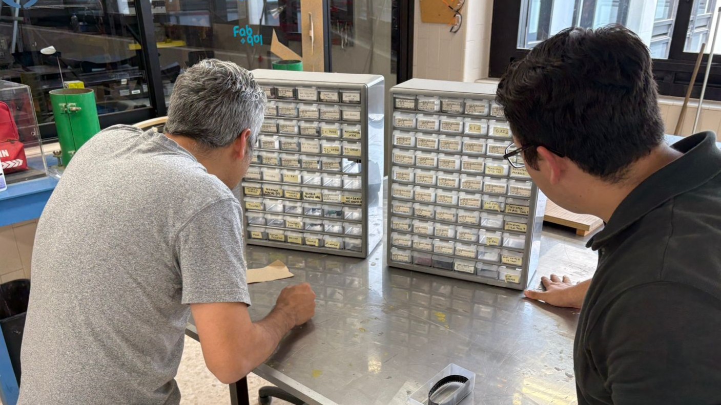
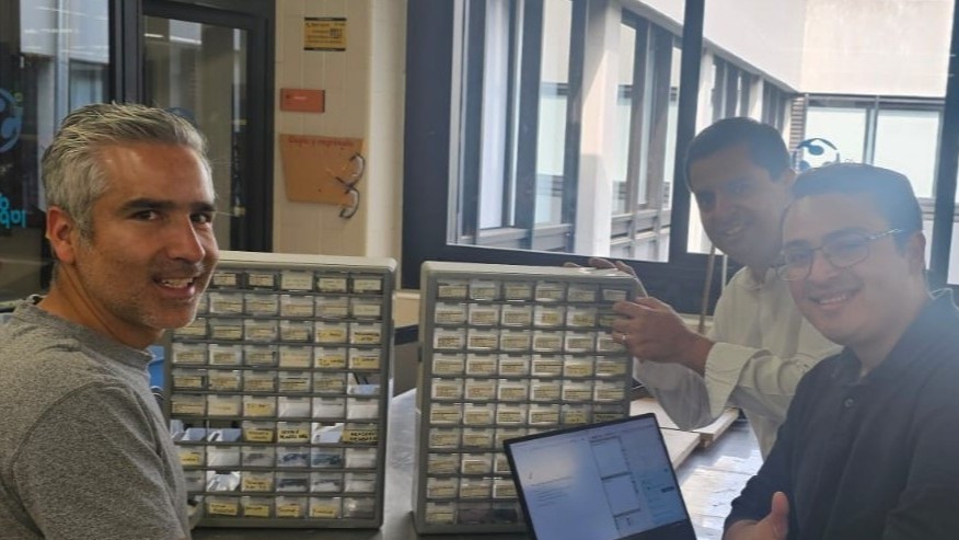
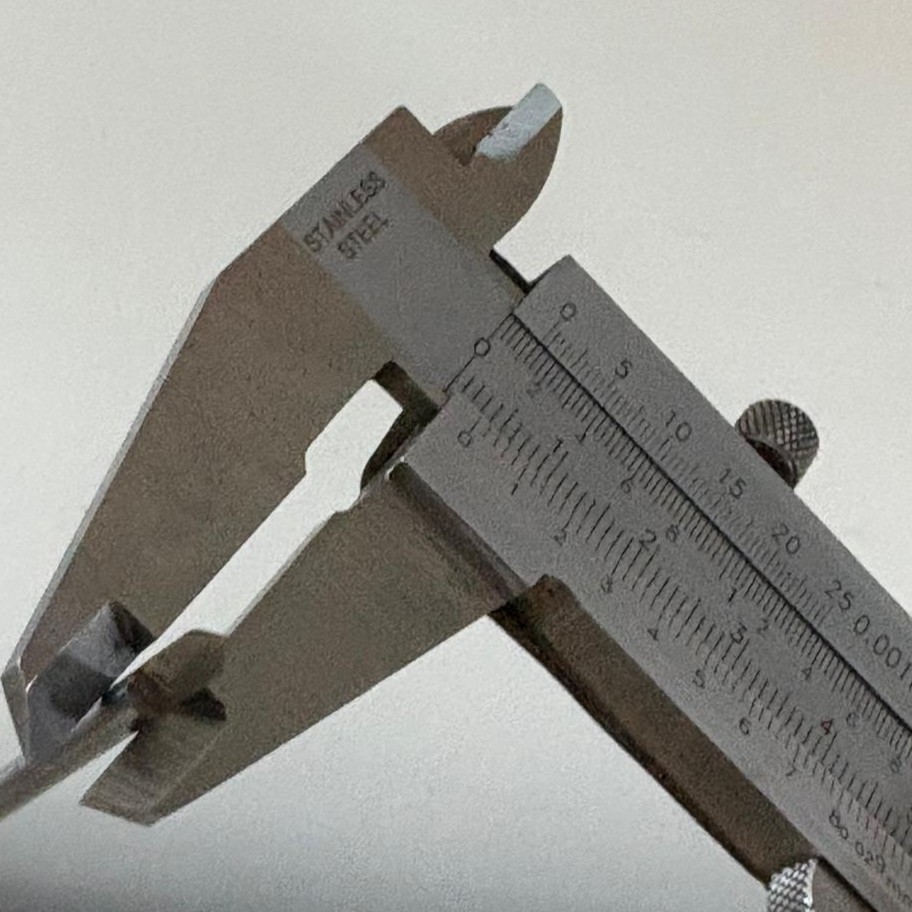
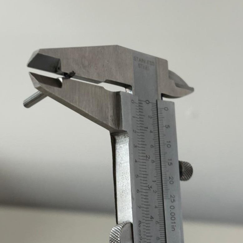
The material thickness was measured to make sure it was suitable for the milling process. For this work, a V-bit was used to mill the traces, while a flat end mill was used to cut the board outline.
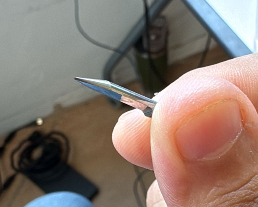
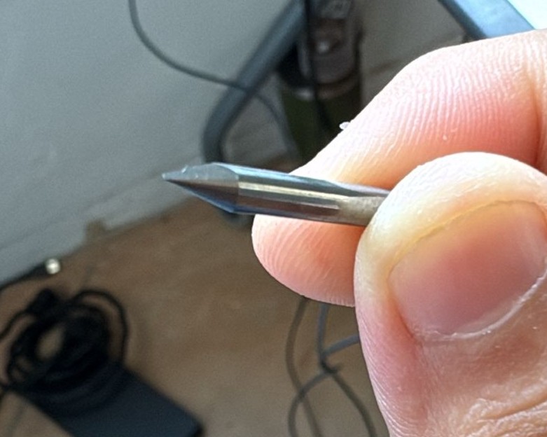
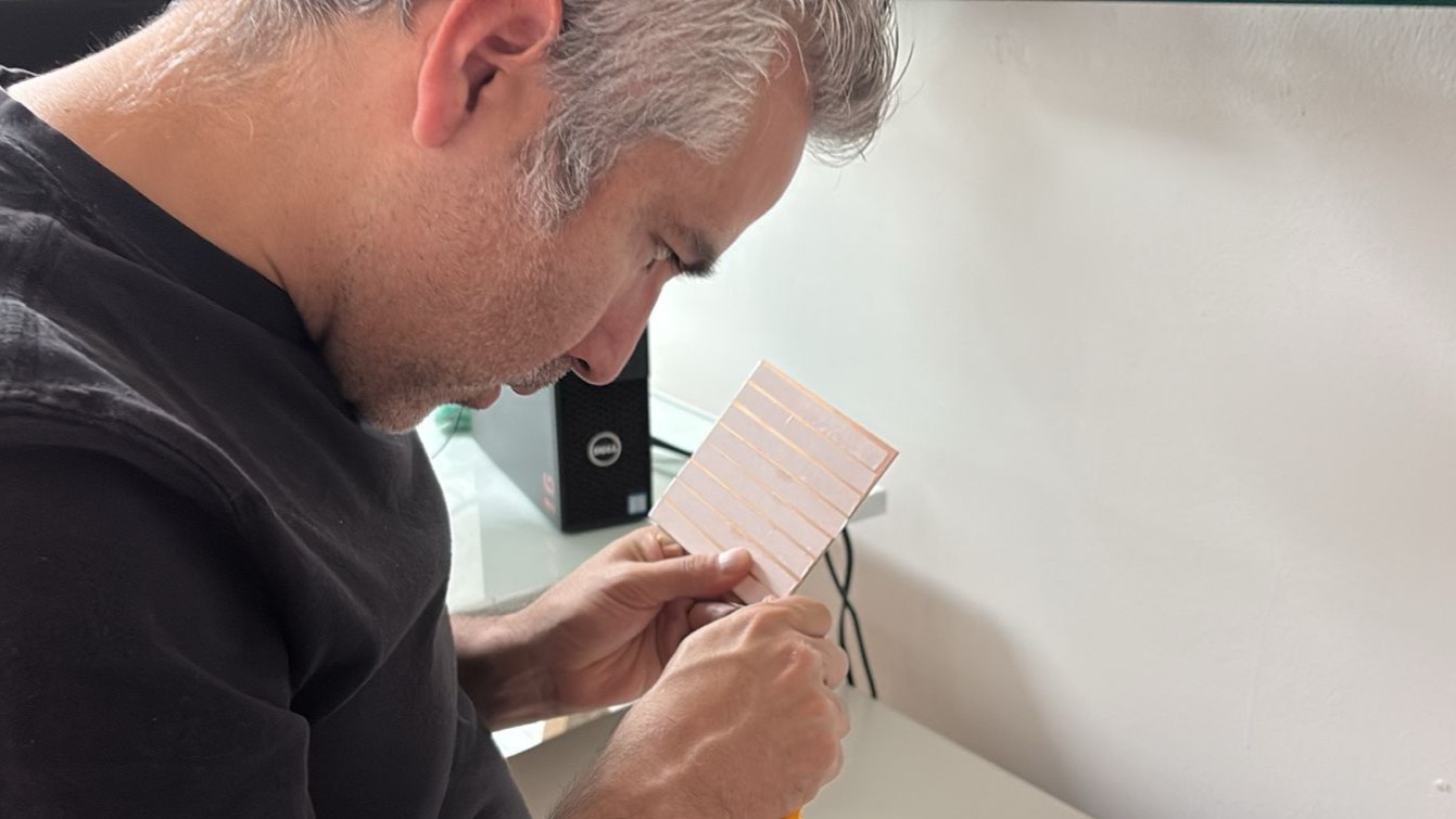
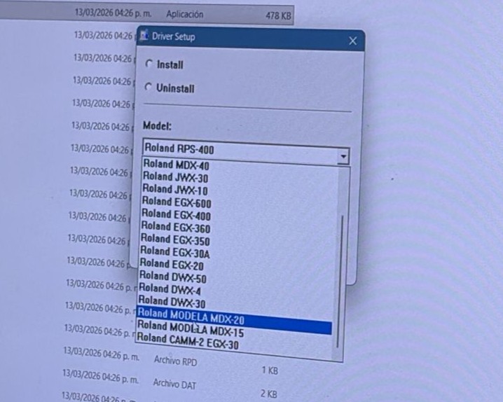
Before starting, it was necessary to install the drivers for the Roland machines. In our case, we used Windows for communication with the machine.
We used MODS to generate the toolpaths and send the machining instructions to the Roland milling machine. This allowed us to process the design files and convert them into commands that the machine could interpret.
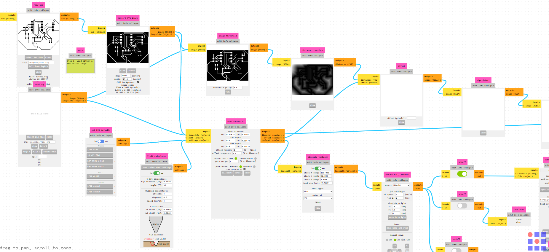
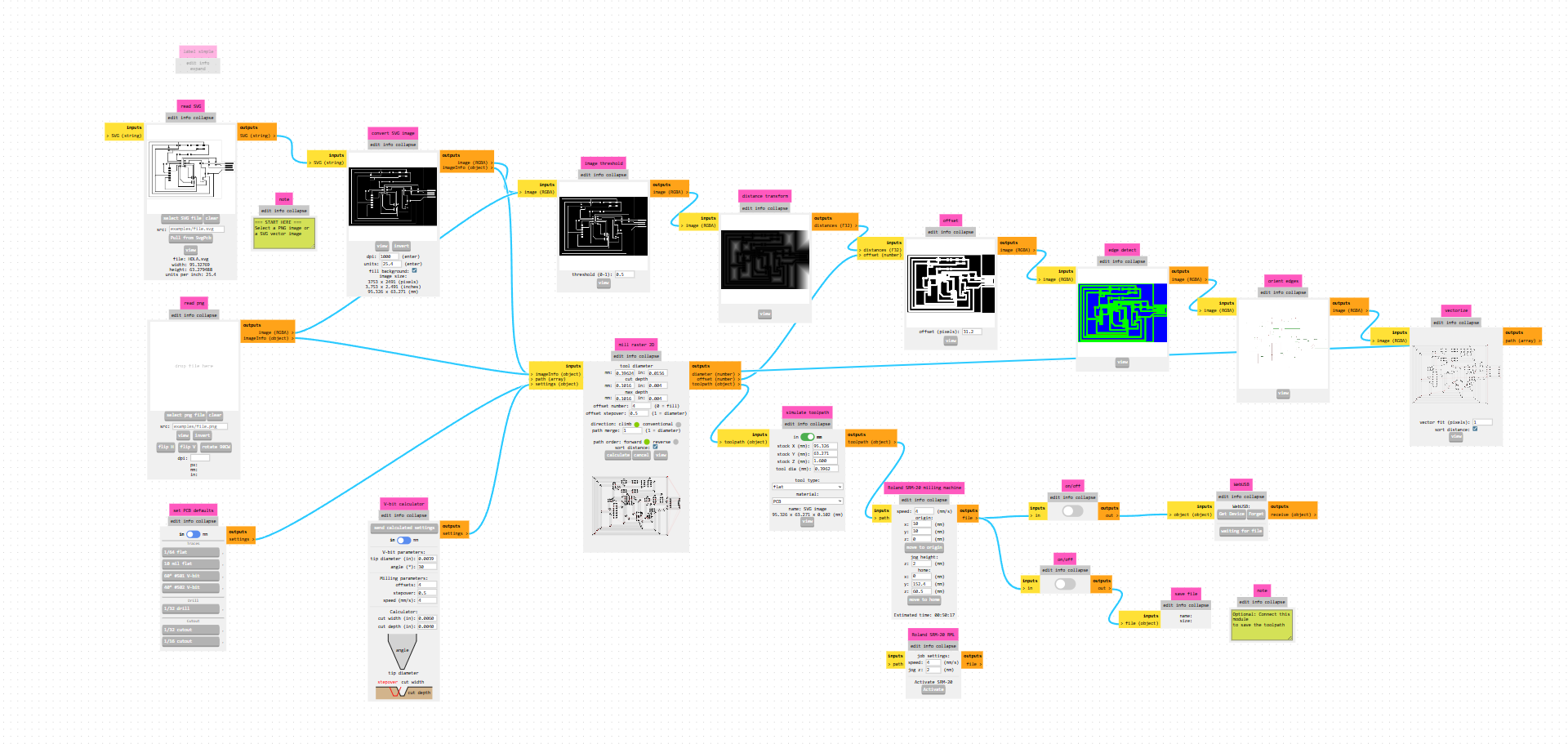
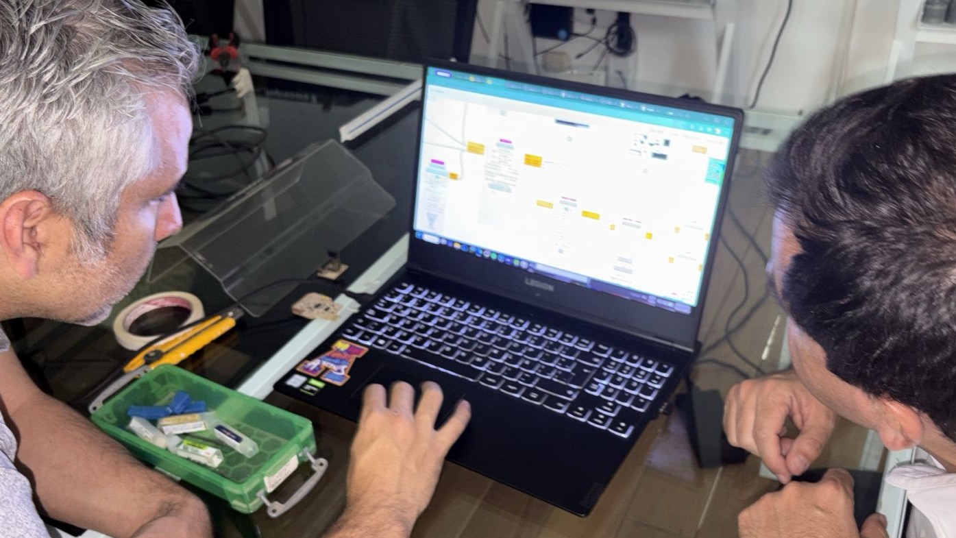
MODS generates an RML file, which is then sent to the Roland milling machine through the control software.
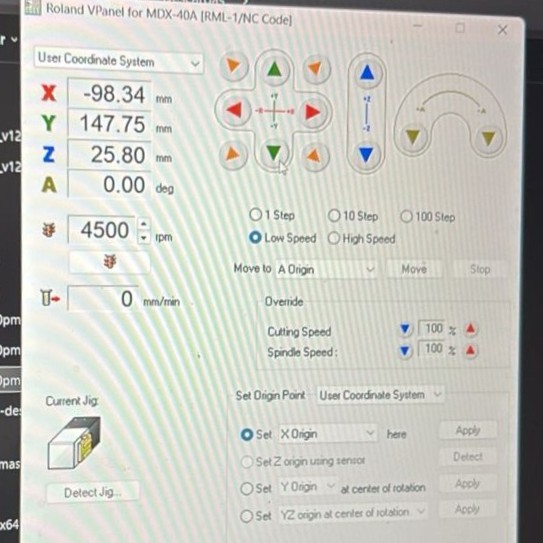
In this step, the file was sent correctly and the milling process was ready to continue.
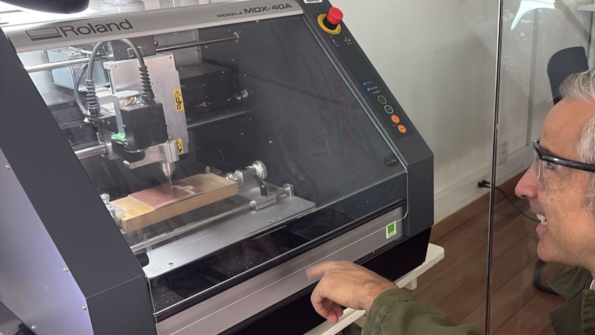
After milling the traces, the tool was changed to an end mill to cut the board outline. This step removed the material around the design and separated the final board from the stock.
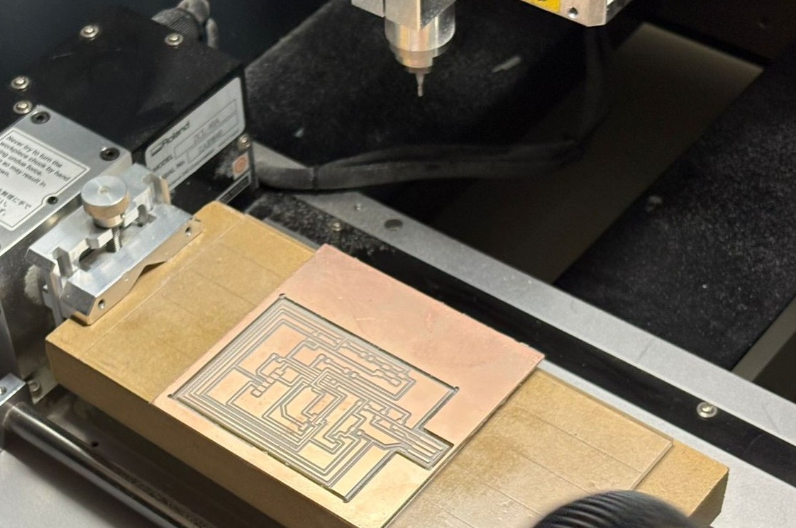
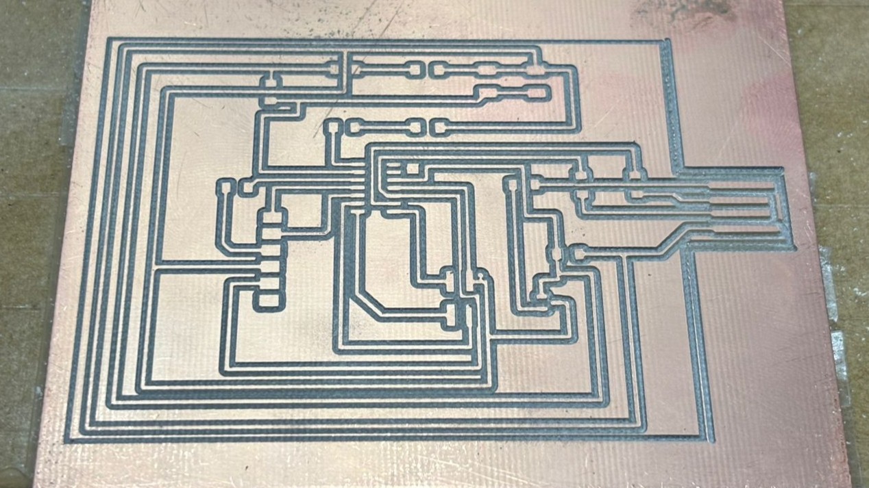
After the cutting process, the surface-mount components were soldered onto the board. This included resistors, capacitors, the microcontroller, LEDs, and connectors.
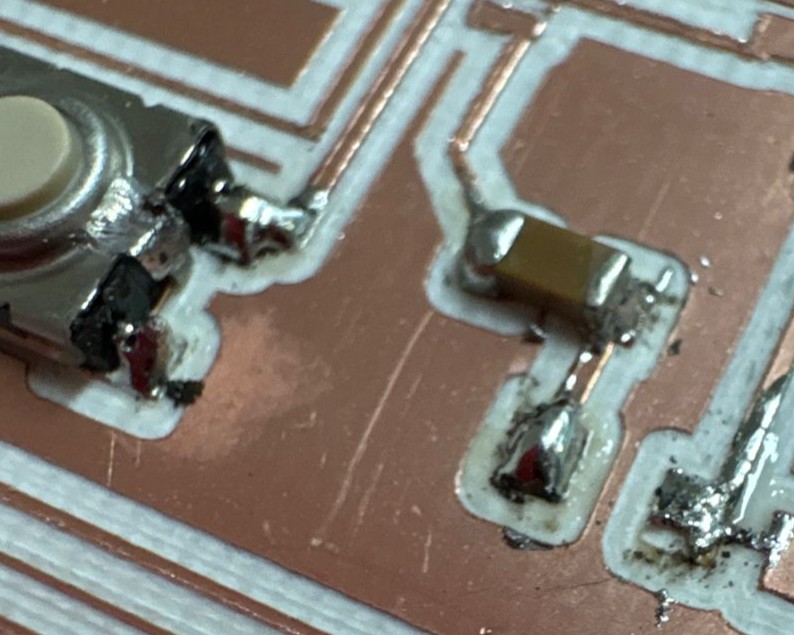
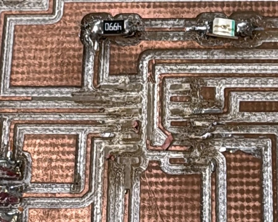
During the soldering process, some quality issues were observed, such as excess solder and small accumulations on certain pads. With patience and practice, the connections were corrected and the board was completed.
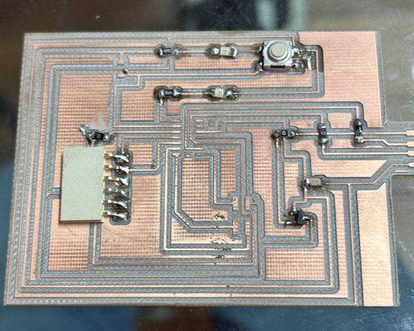
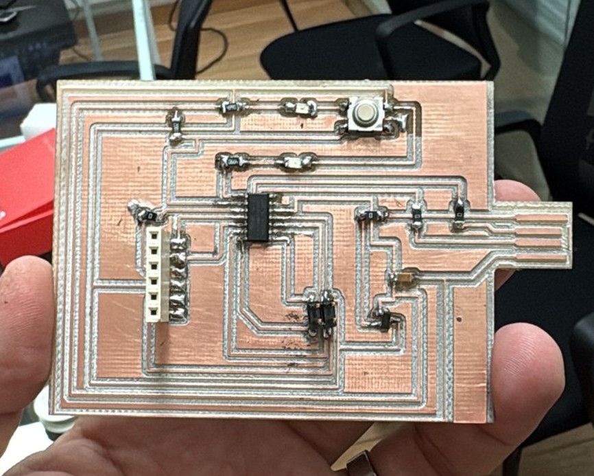
With the workflow established, additional boards were fabricated to continue testing and validating the programming of the microcontrollers.
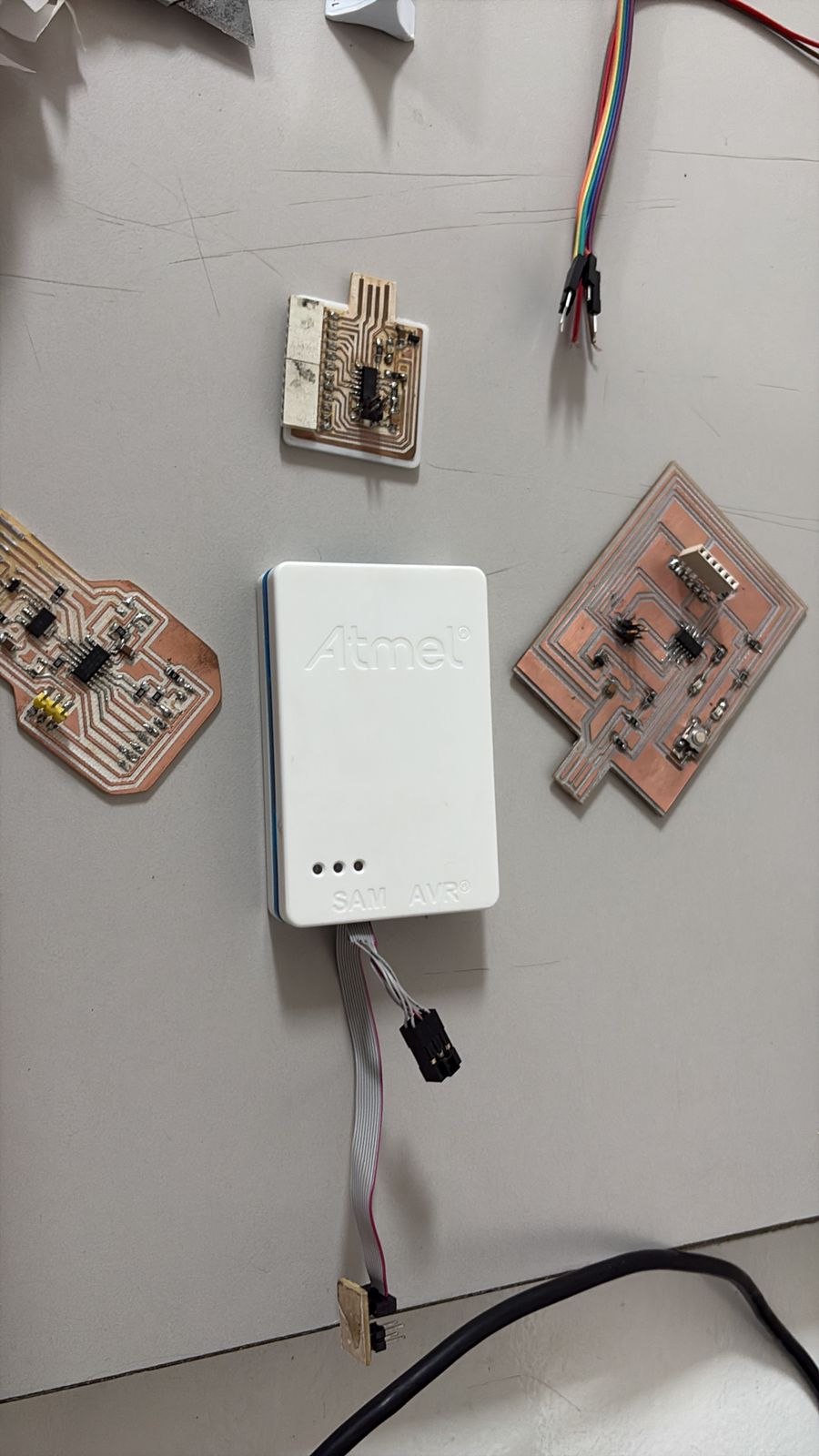
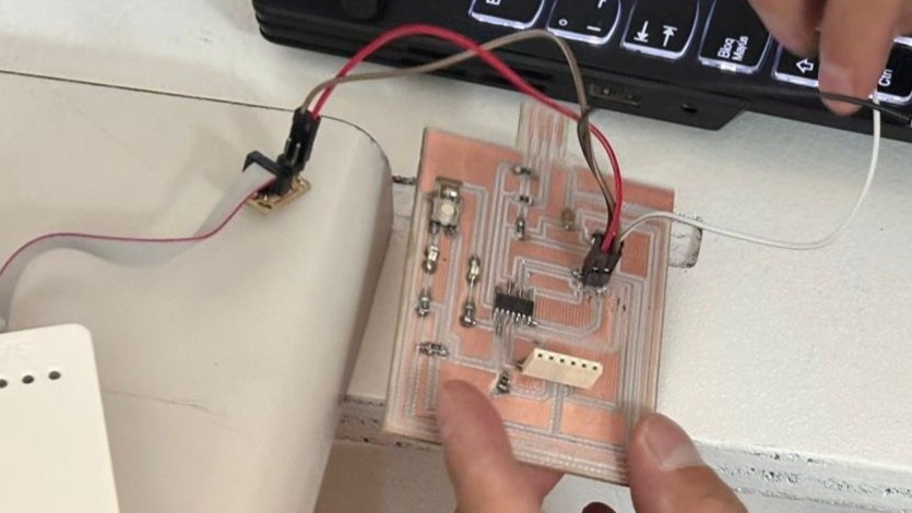
After soldering the components, we found an important mistake: the SAMD microcontroller had been placed in the wrong orientation. Because of this, we had to desolder the components, but some PCB traces were damaged during the process.
At the same time, we were working on another board, so we were able to continue without losing too much time. In this case, we decided to continue the project using a XIAO board.
This stage marked the transition from a passive circuit to a functional system.
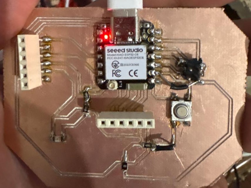
In this test, a solenoid was controlled through the PCB as part of the system being developed. This allowed us to move from basic validation to a functional application, integrating the different elements of the system.