Computer - Controlled Machining
Safety Training
A safety and machine operation training session was carried out before using the CNC router. During this session, the basic machining parameters and some important design considerations for the workflow were explained.
One of the concepts reviewed was pass depth, which refers to the amount of material removed in each tool pass. It was recommended that the cutting depth should be equal to or smaller than the diameter of the cutting tool to avoid overloading the end mill and reduce the risk of tool breakage. Feeds and speeds were also discussed, since they define the rotational speed of the tool and the feed rate used during the cutting process.
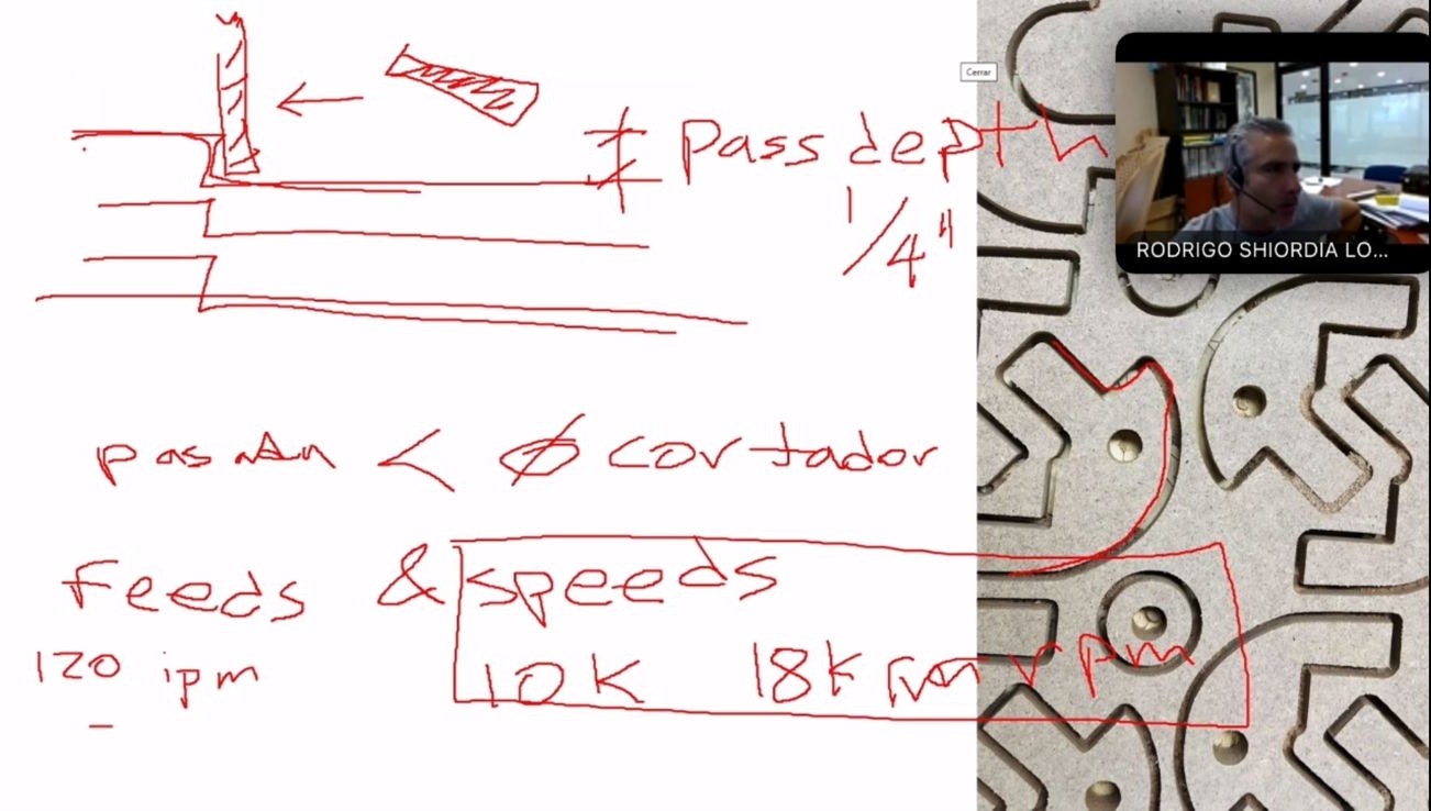
Because end mills are circular, internal corners cannot be perfectly square. This can be solved by adding dogbones, which allow the pieces to fit correctly during assembly.
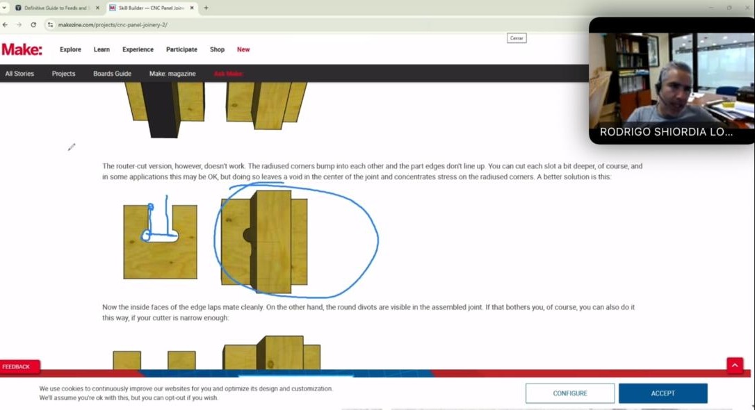
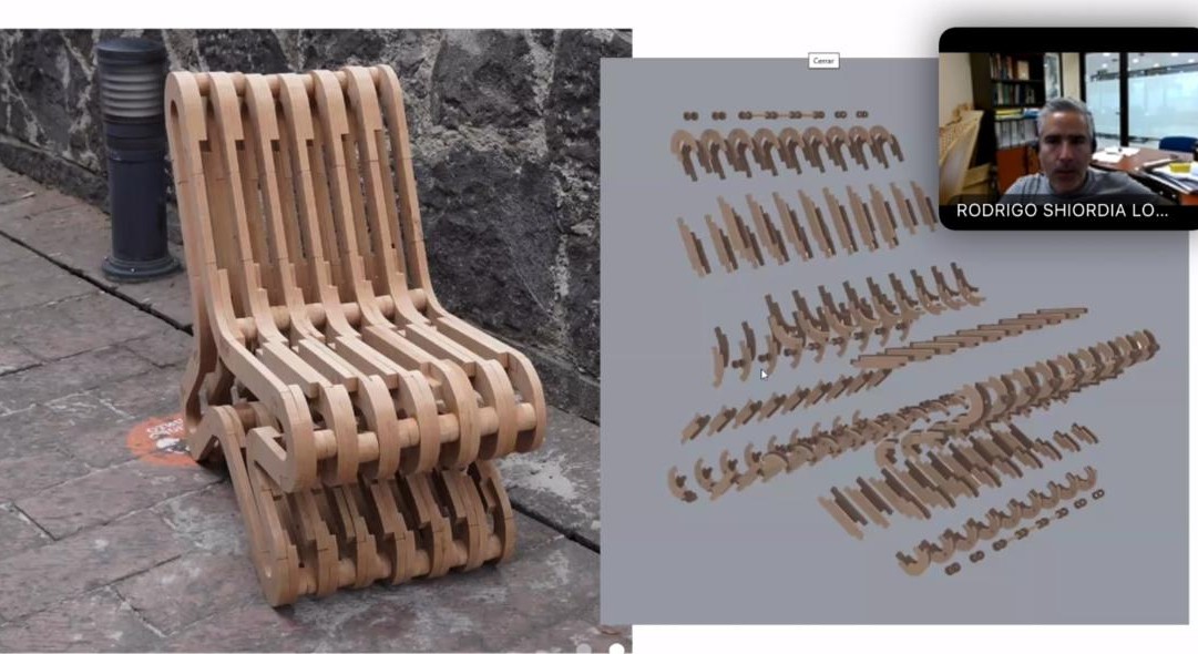
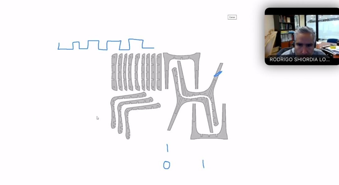
Examples of press-fit structures were also presented. In this type of design, the parts are manufactured from flat sheets of wood or MDF and then assembled through slots, without using screws or glue. This approach makes it possible to fabricate complex objects, such as furniture, using only CNC cutting.
Setup and Toolpath
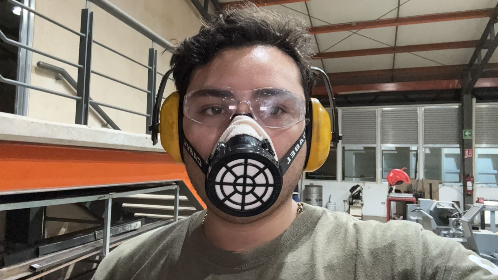
Before starting the CNC router operation, we used the required personal protective equipment: safety glasses, hearing protection, and a filtered respirator. This equipment helps reduce exposure to dust, spindle noise, and possible material projections during machining.
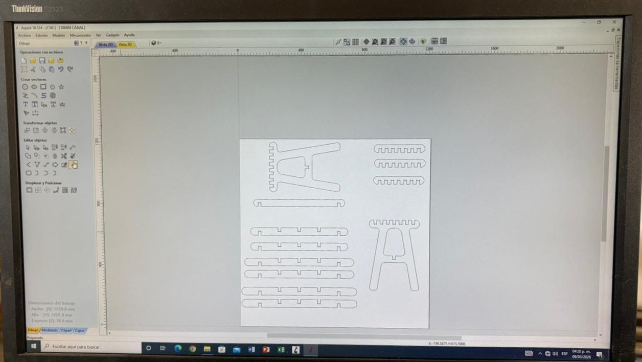
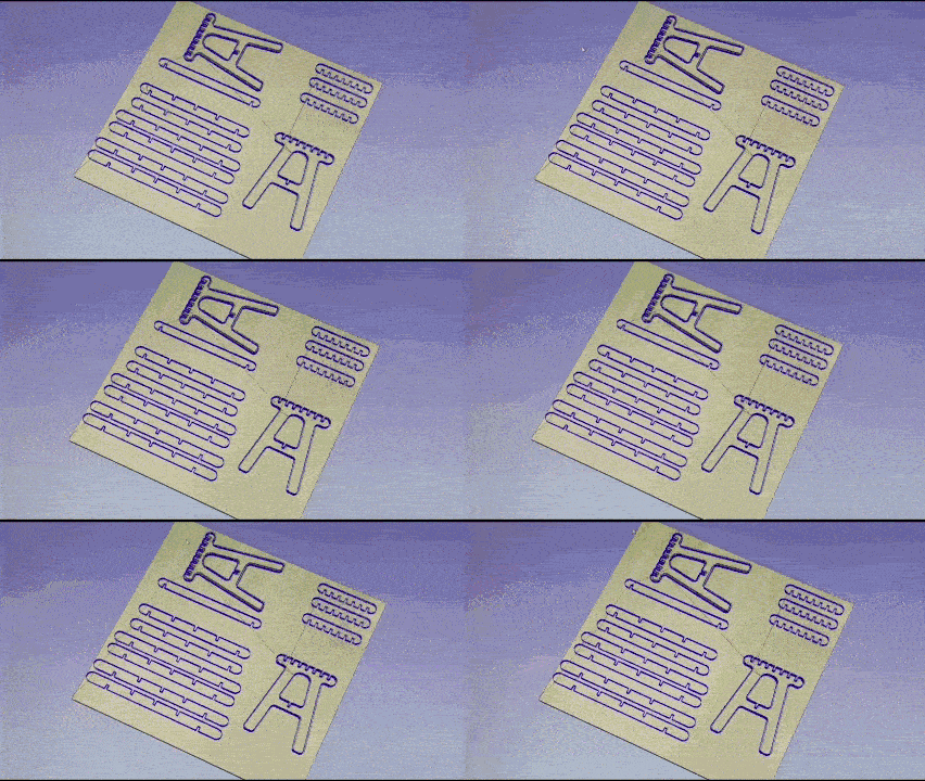
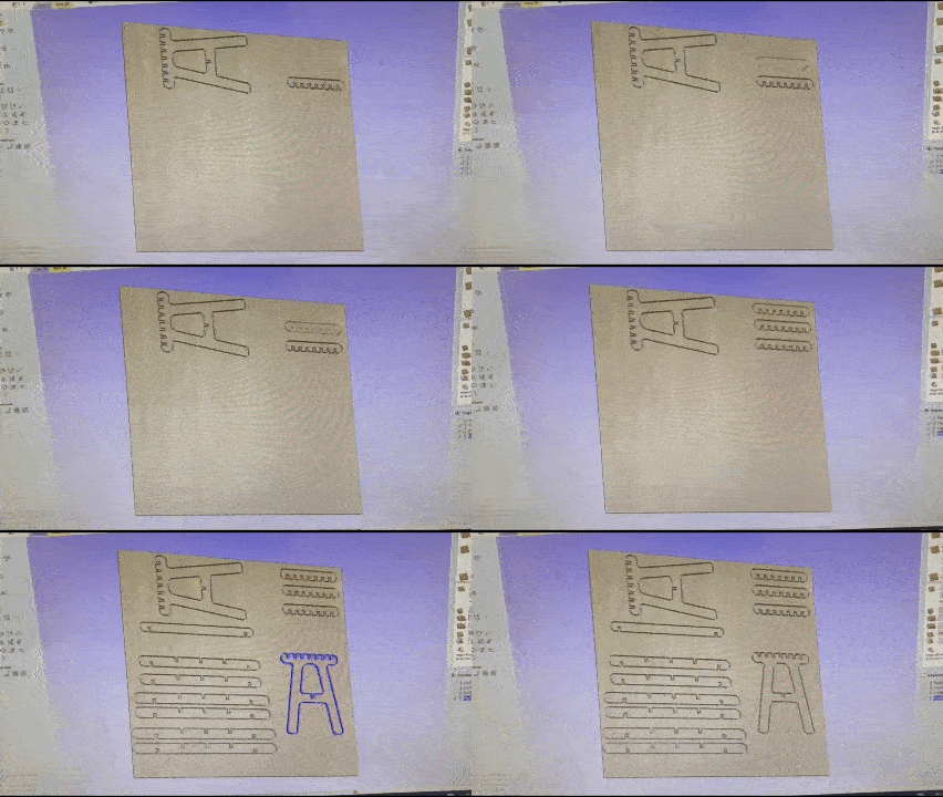
The structure design was imported into Aspire in DWG format. In this software, the cutting operations and toolpaths were defined before exporting the file for the CNC controller.
The geometry of the parts was arranged within the workspace according to the dimensions of the material. In this case, the material used was 18 mm MDF.
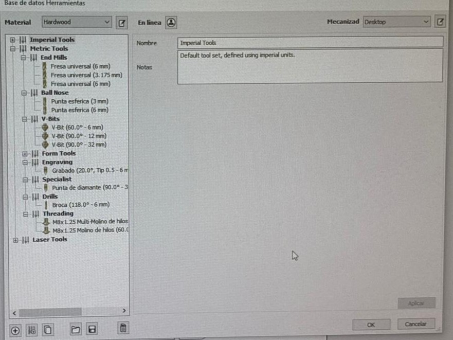
A 6 mm flat end mill was selected from the tool library. This selection was important because the design included several press-fit joints, so the tool diameter had to be considered when defining the cutting paths, cutting depth, feed rate, and spindle speed.
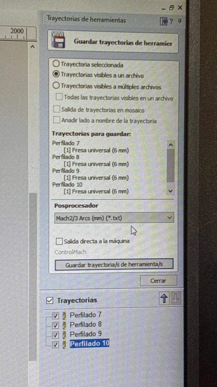
The toolpaths were exported using the Mach2/3 Arcs post-processor in millimeters. This converts the machining operations into G-code that can be read by the Mach3 control software.
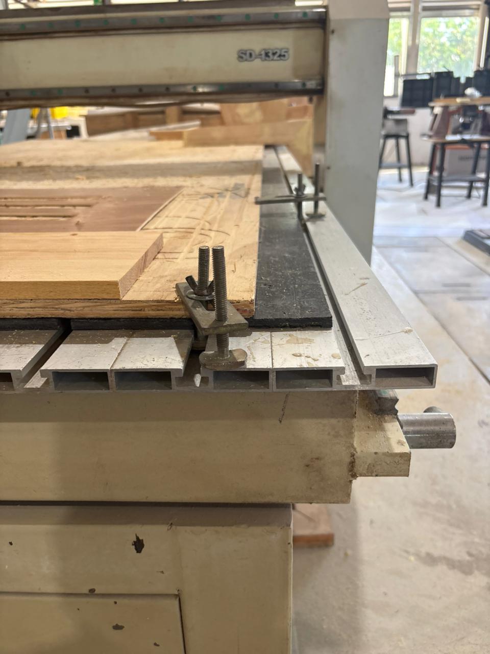
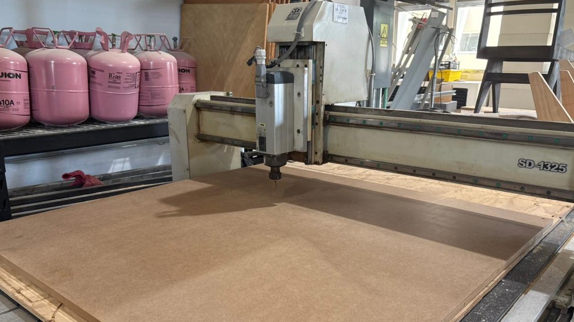
The material clamping system on the CNC worktable uses metal clamps to prevent movement during machining. To avoid possible interference between the cutting tool and the clamps, an additional layer of material was placed under the workpiece.
This layer worked as a sacrificial board. It protects the CNC table when full-depth cuts are made and also helps keep the workpiece stable during the cutting process.
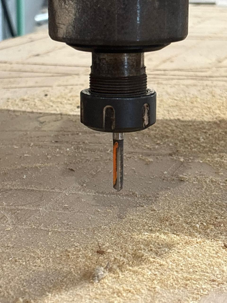
The cutting tool used was a 6 mm flat end mill. It was installed in the spindle to perform the cutting and profiling operations on the MDF board.
Once the material was placed on the worktable, it was secured with the clamping system. Before starting the cut, we checked the board position, the firmness of the clamps, and the available workspace for the generated toolpaths.
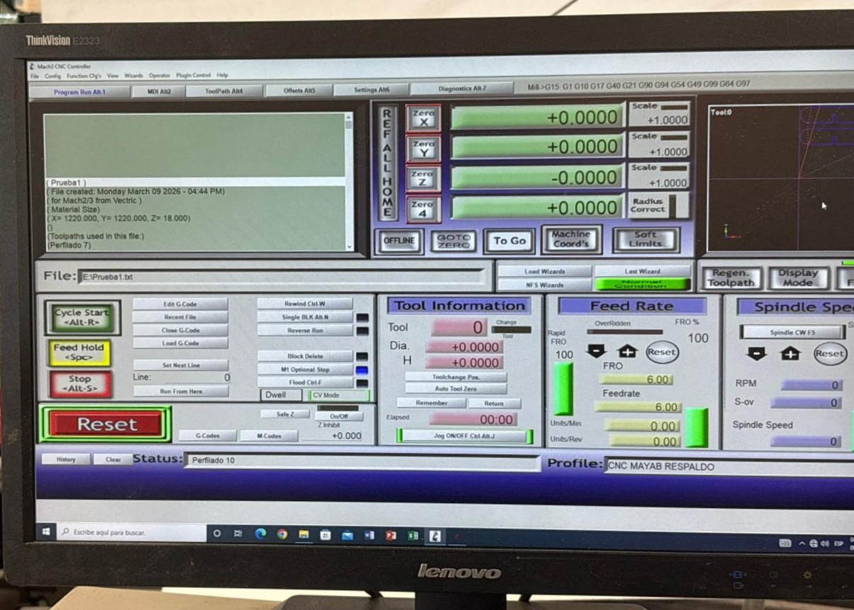
The machining process was controlled using Mach3, which works as the control interface for the CNC machine. This software reads the G-code generated in the CAM software and translates it into movements of the X, Y, and Z axes.
Before starting the machining process, it was necessary to verify the reference coordinates, the tool position, and the available workspace. After these checks, the cut was started using the Cycle Start command.
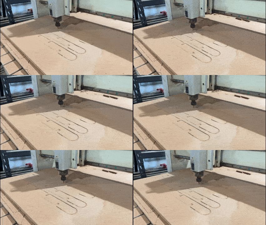
The final piece matched the original design. However, during the machining process, we noticed that the sacrificial layer had some irregularities from previous cuts made on the same machine.
These irregularities slightly affected the stability of the material and caused a small unexpected movement during the cut. Even with this issue, the geometry of the piece was machined successfully and the toolpaths were completed as intended.