Electronics Design

To control the solenoid, I designed a low-side driver using an N-channel MOSFET, a gate resistor, a pull-down resistor to ground, and a flyback diode connected in parallel with the coil. Since the simulator did not include the exact solenoid component, I first modeled the load as an equivalent RL circuit. This allowed me to observe the current response and the way the energy stored in the coil is dissipated when the circuit is switched off. The simulation was useful to verify the circuit behavior and to confirm the importance of the flyback diode for protecting the MOSFET from voltage spikes.
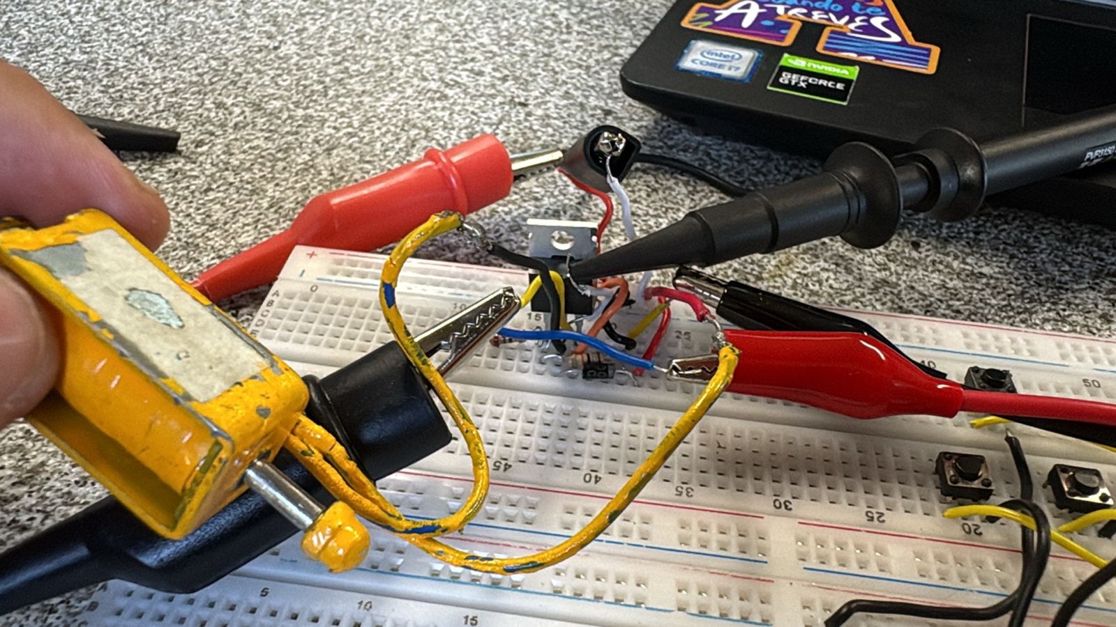
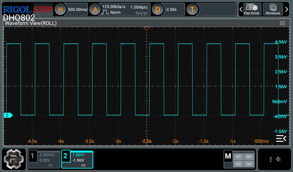
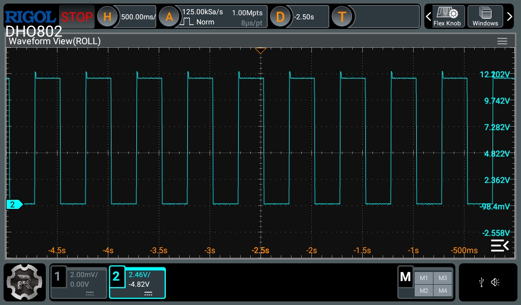
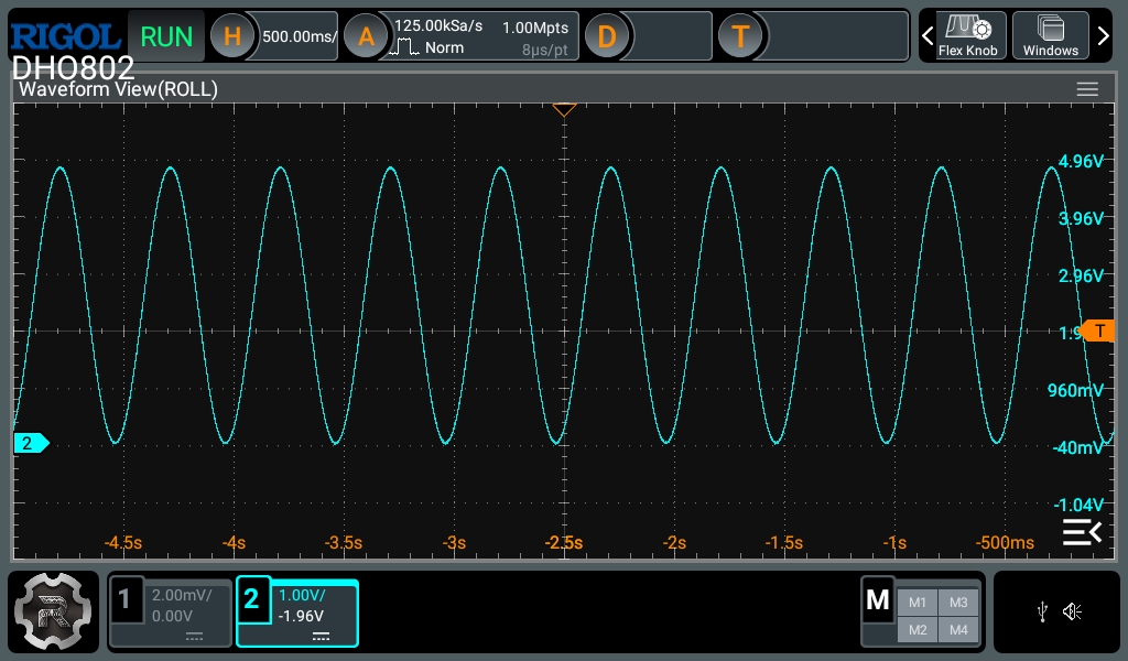
For the physical test, I used a 0–5 V square wave to drive the MOSFET gate. On the oscilloscope, the gate signal measured approximately 0–4.96 V, while the drain signal changed from about 12.20 V to 0.10 V. This confirmed that the MOSFET was switching properly and that the solenoid was being energized. A small overshoot was observed at the drain, which is expected when working with an inductive load. However, this test also showed that the final MOSFET must be selected based on its RDS(on) at the actual gate-drive voltage, not only by looking at its VGS(th).