System Integration — Smart Beehive
This week focuses on integrating all the subsystems of my final project — the Smart Beehive — into one coherent system. The beehive combines cameras, environmental sensors, load cells, a servo-controlled entrance, LED lighting, and network connectivity, all managed by a single Raspberry Pi 5 powered over Ethernet.
Assignment Requirements
Individual Assignment:
- Design and document the system integration for your final project
System Overview
The Smart Beehive integrates the following subsystems:
- Raspberry Pi 5 (8GB) — main controller, powered via PoE
- Waveshare PoE HAT (F) — delivers power and network over a single Ethernet cable
- 2× Raspberry Pi Camera Module 3 Wide — entrance monitoring, one per entrance half
- Servo motor — remotely opens and closes the hive entrance
- 4× LED boards — 2 white (daytime) and 2 red (nighttime) for camera illumination
- 3× SHT45 temperature/humidity sensors — via I²C multiplexer (TCA9548A)
- Load cells — weight monitoring for honey production and colony health
- Entrance housing — white ASA filament for UV/weather durability
3D CAD Models — Electronics Packaging
I designed two custom housings in Fusion 360 to package the electronics and cameras into the beehive. Both parts are 3D printed — the bottom board in PLA (interior, protected from weather) and the entrance in white ASA (exterior, UV/weather resistant).
Bottom Board
The bottom board is the main electronics enclosure. It holds the Raspberry Pi 5, the Waveshare PoE HAT, the I²C multiplexer, and all wiring. It mounts underneath the hive body and keeps everything organized and protected from the bees. The board has mounting posts for the Pi, cable routing channels, and ventilation slots for the PoE HAT's cooling fan.
Bottom Board — holds the Raspberry Pi 5, PoE HAT, and other electronics. Click and drag to rotate, scroll to zoom.
Entrance Camera Housing
The entrance housing mounts at the hive entrance and holds both Pi Camera Module 3 Wide units and the 4 custom LED PCBs (2 white, 2 red). It's designed so the cameras have a clear view of bees entering and exiting, while the LEDs provide illumination without being in the cameras' field of view. The housing also integrates with the servo-driven rotating entrance gate.
Entrance Camera Housing — holds both cameras and LED boards at the hive entrance. Click and drag to rotate, scroll to zoom.
Printed Housing — Final Result
The entrance housing and bottom board have been 3D printed — entrance in white ASA (weather/UV resistant) and the bottom board in PLA (interior, protected from elements).
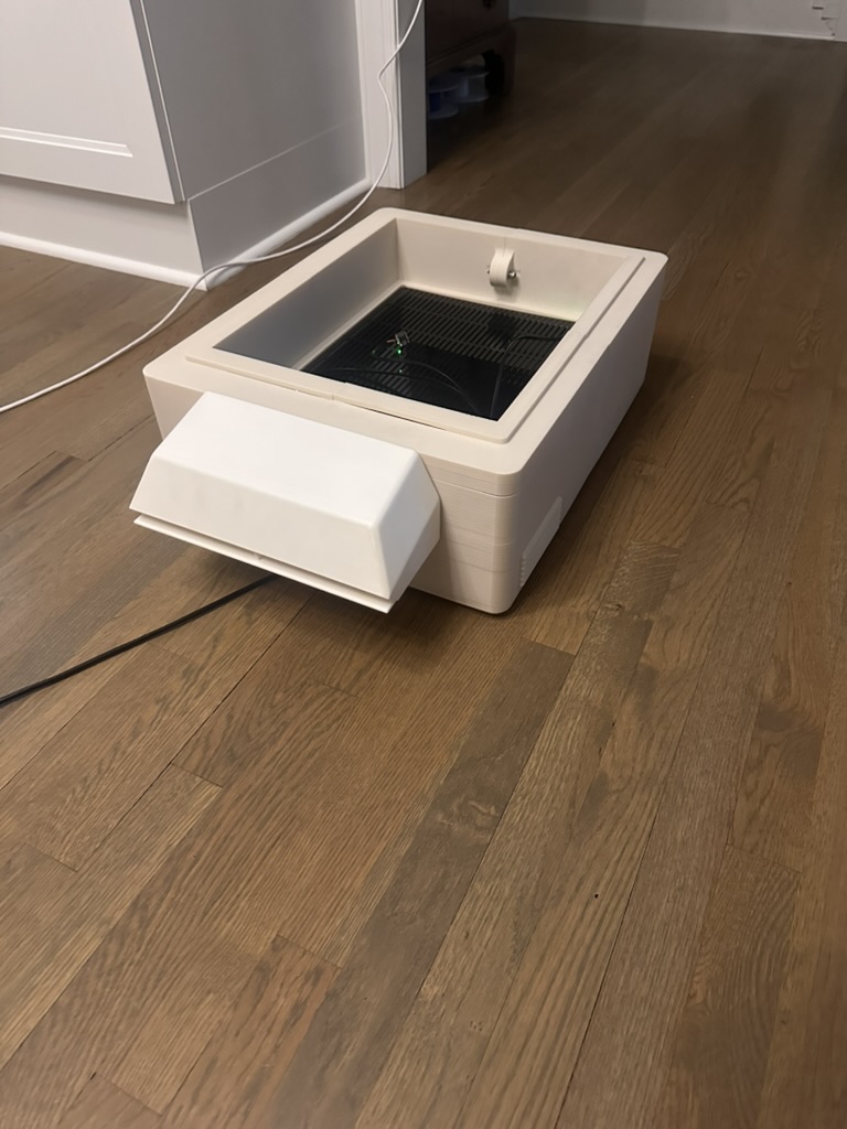
Final 3D printed housing — entrance in white ASA, bottom board in PLA
System Assembly
Getting everything wired up and installed into the enclosure. My dad helped hold the wires in place during this step — I was having trouble keeping the ribbon cables plugged in while simultaneously routing everything into the housing.
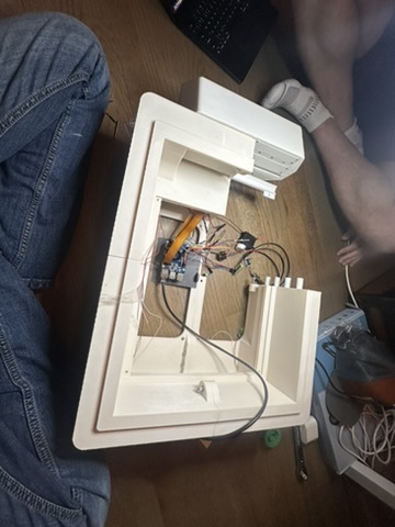
Getting the Pi wired up before putting it in — my dad helped ensure all the ribbon cable connections stayed in place
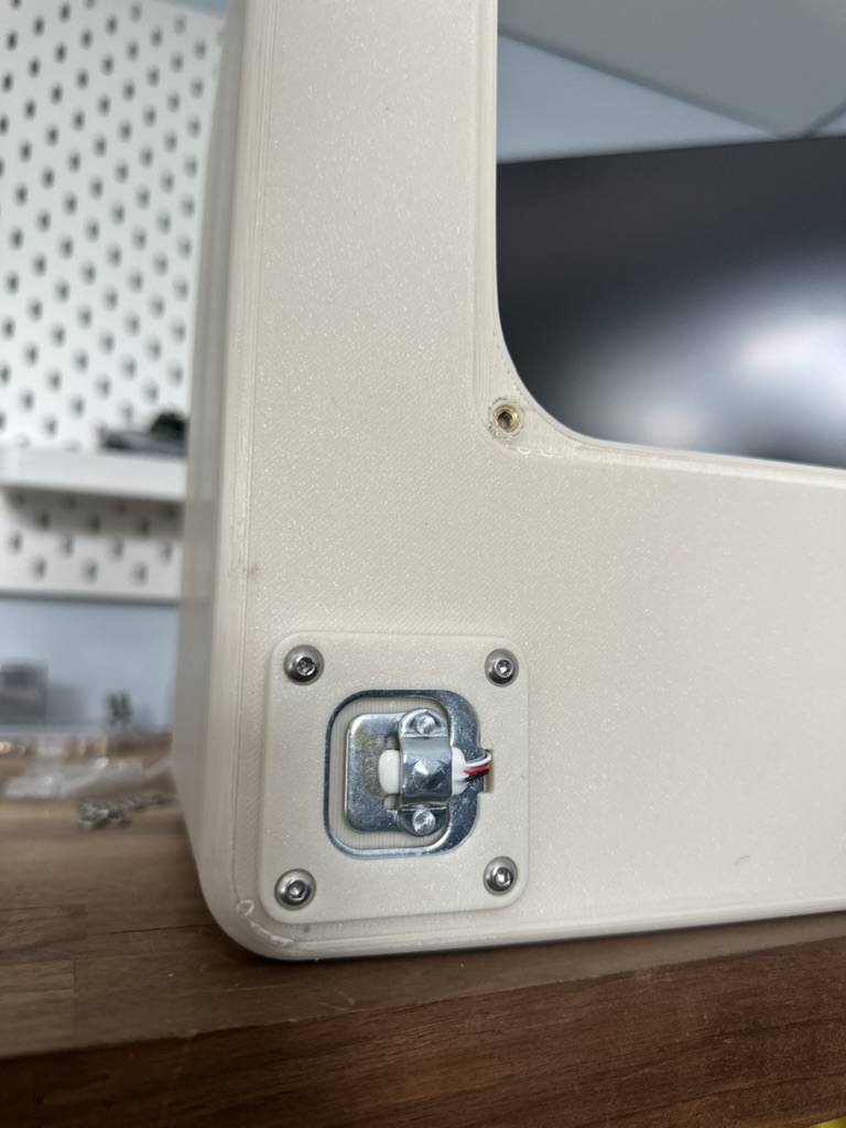
Integrated load cells mounted in the bottom board section
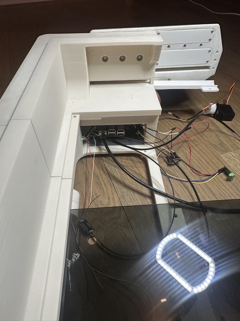
Pi fully installed in the bottom board enclosure — all cables routed and secured
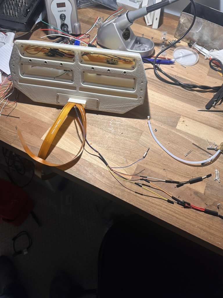
Wired up entrance housing — cameras and custom LED PCBs installed and connected
Design Files
Download the STL files for 3D printing:
Power & Networking — PoE Change
Previously I was planning to use a large battery with a complex power supply system, but I've switched to Power over Ethernet (PoE). This simplifies everything — one Ethernet cable from the house to the hive carries both data and power. No batteries to recharge, no 140W solar panel, no power management circuitry.
Waveshare PoE HAT (F) for Raspberry Pi 5
- Standard: 802.3af/at compliant — works with any standard PoE switch or injector
- Power: High-power output to drive the Pi 5 plus peripherals
- Cooling: Onboard cooling fan with metal heatsink — important since the Pi 5 runs hot, especially when streaming two camera feeds
- Network: Gigabit Ethernet to the Pi — much more reliable than WiFi over 500 feet to the hive
- Benefit: A single cable handles power AND data, cutting down on wiring complexity at the hive
Entrance Housing — Material Choice
The entrance housing is 3D printed in white ASA filament. ASA was chosen because:
- UV resistance: ASA is specifically engineered for outdoor use and resists UV yellowing and brittleness much better than PLA or PETG over time
- Weather durability: Handles rain, humidity, and temperature swings without warping or degrading
- White color: Reflects heat rather than absorbing it — important for keeping the hive cool in summer
- Strength: Tough and impact-resistant, holds up to bee activity and occasional bumps during inspection
Interior Parts — PLA
For parts that stay inside the hive or electronics housing (not exposed to the elements), I'm using PLA. PLA is cheaper, prints easily, and holds up fine when it's not dealing with UV or moisture. Using ASA only where it's needed saves material cost and simplifies printing for the interior components.
Print-Size Challenge — Entrance Housing
The entrance housing is too large to print on my Bambu A1 in one piece. My approach:
- Test print one half on my A1 — I printed half of the entrance housing at home to verify the design. This let me test-fit the Pi Camera Module 3 and my custom LED PCB before committing to a full-size print. Catching any issues at this stage saved me from paying for a failed large print.
- Reached out for quotes — I contacted several people and services about printing the full-size part in ASA. A person on Facebook in Georgia with a Bambu H2 quoted $125 but the deal fell through. PCBWay quoted $200 for the camera box alone. The cost is high for a single part, so I'm still exploring options — possibly printing it at school on the X1 printers if I can split the design into pieces that interlock while staying waterproof.
Print Settings Planned
- Extra fine precision — for a smooth surface finish that looks clean on the finished hive
- 5-layer wall thickness — extra walls for waterproofing, since ASA is outdoor-rated but layer-line seams are still a potential water ingress path
- Gyroid infill — strong in all directions, good balance of strength and print time
ASA specifically requires a heated chamber to print reliably at this size — without one, ASA warps, cracks, and delaminates on large parts. A Bambu H2, Bambu X1C with enclosure, or professional print service like PCBWay all have the enclosed chamber and heated build volume needed for this. If I end up making a lot more of these housings in the future, I'd invest in my own enclosed printer rather than continuing to outsource.
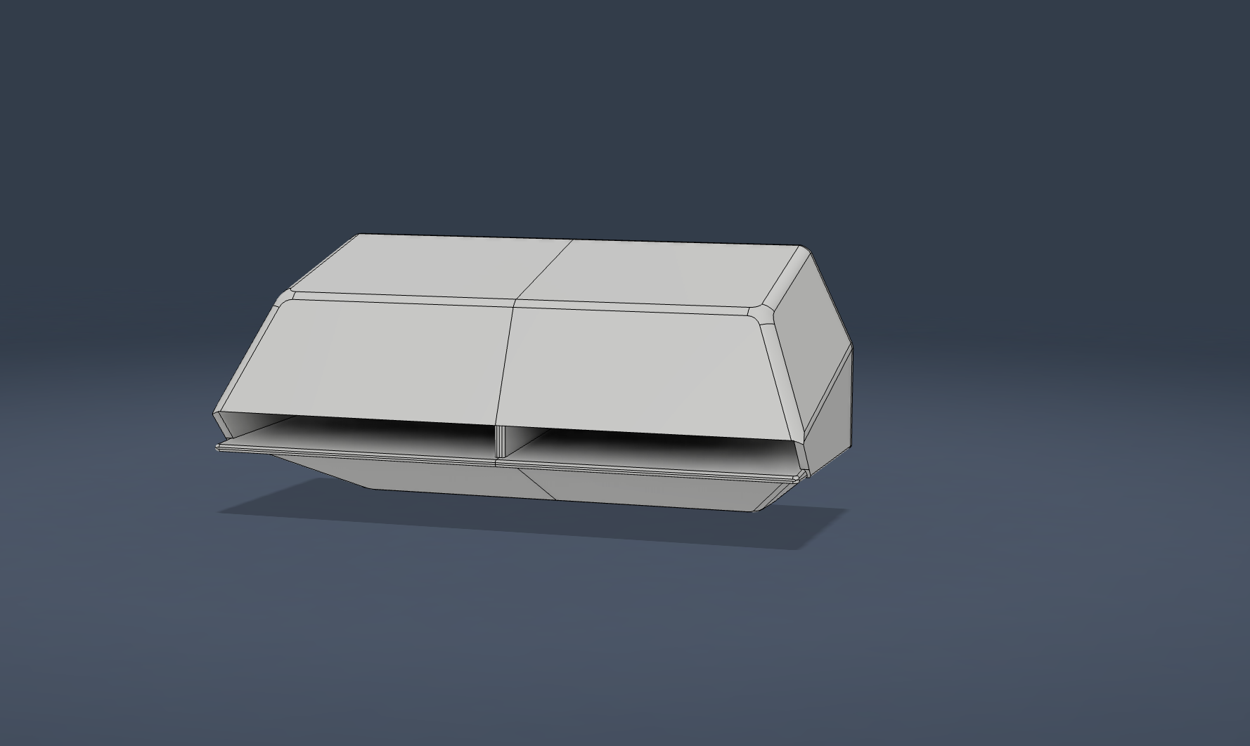
Entrance camera box — houses both Pi Camera Module 3 units and the LED boards
Servo-Controlled Entrance Gate
The hive entrance has a rotating gate that opens and closes the entrance digitally. This is driven by a servo motor through a belt drive.
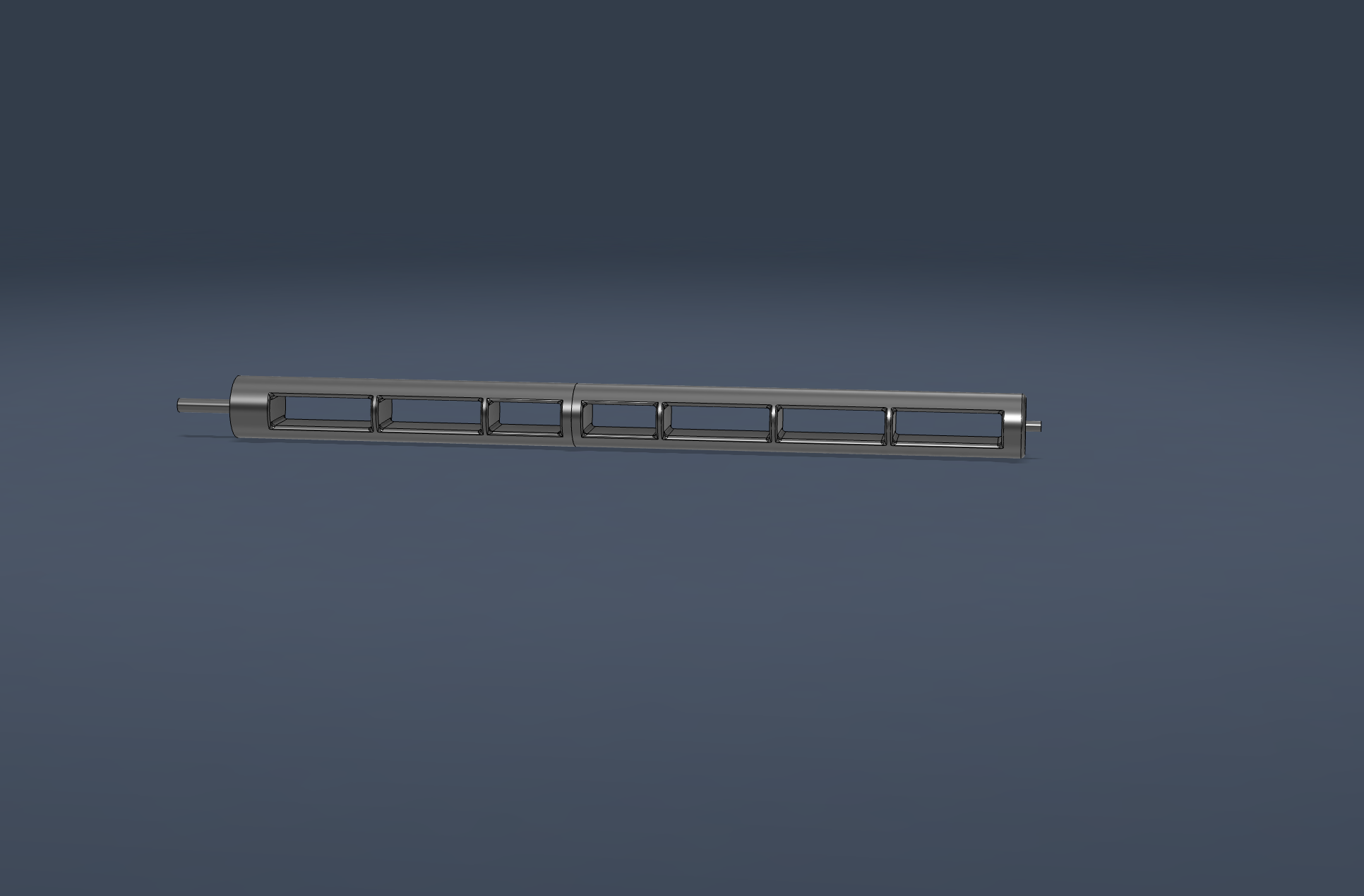
The rotating entrance gate — driven by a servo motor through a belt drive
I successfully printed the rotating entrance as the final part on my Bambu A1 in PLA. Since the rotating gate sits inside the entrance housing — enclosed and shielded from direct UV and weather — PLA is fine here. The housing around it handles the outdoor exposure, so the gate itself doesn't need ASA or PETG.
Why a Belt Drive?
A belt drive separates the servo from the rotating part, giving me flexibility in where the servo is mounted and how the gearing is arranged. It also gives mechanical advantage if I need torque multiplication, and isolates the servo shaft from any side-loads the gate might experience.
Why Move the Servo Slowly?
The servo needs to move slowly for two reasons:
- Protect the Pi's power supply: Servos draw a large inrush current when they start moving, especially under load. If the servo slams from one position to another at full speed, it can cause a voltage dip on the Pi's power rail — potentially causing brownouts, SD card corruption, or unexpected reboots. Moving slowly spreads the current draw over time and keeps the rail stable.
- Don't startle the bees: A fast-moving gate next to the hive entrance would disturb the colony. Slow, gradual movement is much less alarming.
The Pi will ramp the servo position gradually instead of commanding it to slam from 0° to 180° instantly.
Daily Anti-Propolis Movement
The system is programmed to automatically move the gate a small amount a few times a day. This prevents the bees from sealing the gate shut with propolis.
What is propolis? Propolis is a sticky, resinous substance bees collect from tree buds and sap flows. They use it as a hive sealant — filling cracks, smoothing rough surfaces, and even mummifying intruders that are too large to remove. Bees will gradually coat any gap or moving joint in the hive with propolis, and over time it can seize up mechanical parts completely.
By moving the gate a few millimeters several times a day, the system breaks up any propolis buildup before it can harden and lock the mechanism. The movements are small and slow so the bees aren't disturbed, but frequent enough to keep the gate operable.
Subsystem Integration
Cameras
Two Raspberry Pi Camera Module 3 Wide units connect to the Pi 5's dual CSI ports (CAM0 and CAM1). Full documentation of the dual-camera MJPEG streaming setup is on the Week 11 — Networking and Communications page.
Environmental Sensors
Three SHT45 temperature/humidity sensors (with PTFE protection) are placed throughout the hive to monitor different zones — one per box. Because all three sensors share the same I²C address, they're connected through a TCA9548A I²C multiplexer that lets the Pi select which sensor to read. Full sensor details are on the Week 9 — Input Devices page.
Load Cells
Load cells under the hive measure total weight. Weight trends indicate honey production during a nectar flow, honey consumption in winter, and can alert to sudden changes (robbing, swarming, or a lost colony). The load cells interface to the Pi via an HX711 amplifier.
Servo-Controlled Entrance
A servo motor drives a rotating gate at the hive entrance through a belt drive — full details in the Servo-Controlled Entrance Gate section above. This allows the entrance to be opened or closed remotely from the Pi, useful for:
- Closing the hive before moving it (transportation to a new apiary)
- Restricting entrance size in winter to reduce heat loss and deter pests
- Closing the hive during pesticide application in nearby fields
- Testing bee activity patterns by controlled entrance timing
LED Lighting
Four custom LED PCBs (2 white, 2 red) provide illumination for the cameras. White LEDs for daytime viewing, red LEDs for nighttime viewing since bees cannot see red light. Each board is controlled by a single GPIO pin from the Pi via a MOSFET. Full board design is on the Week 10 — Output Devices page.
System Diagram
┌─────────────────────────────────────────────────────────────────┐
│                  SMART BEEHIVE SYSTEM (PoE)                      │
└─────────────────────────────────────────────────────────────────┘

    ┌──────────────────┐
    │   House (500ft)  │
    │  PoE Switch /    │
    │  PoE Injector    │
    └────────┬─────────┘
             │
             │ Single Ethernet Cable
             │ (Power + Data, 802.3af/at)
             │
    ┌────────▼──────────────────────────────────────┐
    │     WAVESHARE PoE HAT (F) — Pi 5              │
    │     • 802.3af/at compliant                    │
    │     • Onboard cooling fan + metal heatsink    │
    │     • Gigabit Ethernet                        │
    └────────┬──────────────────────────────────────┘
             │
    ┌────────▼──────────────────────────────────────┐
    │         RASPBERRY PI 5 (8GB RAM)               │
    │         Main Controller                        │
    └──┬──┬──┬──┬──────────────────────────┬────────┘
       │  │  │  │                          │
       │  │  │  │ GPIO                     │ I²C
       │  │  │  └──────┐                   │
       │  │  │         │                   │
       │  │  └──CSI────┴──CSI────┐    ┌────▼──────────────┐
       │  │                      │    │ TCA9548A          │
       │  │  ┌──────┐    ┌──────┐│    │ I²C Multiplexer   │
       │  │  │ CAM  │    │ CAM  ││    └────┬──────────────┘
       │  │  │  0   │    │  1   ││         │
       │  │  └──────┘    └──────┘│    ┌────┴─────┬─────┬─────┐
       │  │                      │    │          │     │     │
       │  │                      │   ┌▼──┐     ┌▼──┐ ┌▼──┐ ┌▼──┐
       │  │                      │   │SHT│     │SHT│ │SHT│ │SHT│
       │  │                      │   │45 │     │45 │ │45 │ │45 │
       │  │                      │   └───┘     └───┘ └───┘ └───┘
       │  │                      │
       │  │                 ┌────▼────┐
       │  │                 │ LED PCBs│ (4 total)
       │  │                 │ 2×white │
       │  │                 │ 2×red   │
       │  │                 └─────────┘
       │  │
       │  └─────┐
       │        │
    ┌──▼──┐  ┌──▼──────┐
    │HX711│  │ SERVO   │
    │  +  │  │ MOTOR   │
    │LOAD │  │(entrance│
    │CELLS│  │ gate)   │
    └─────┘  └─────────┘

┌─────────────────────────────────────────────────────────────────┐
│  ENTRANCE HOUSING                                                │
│  • White ASA filament (UV resistant, weatherproof)              │
│  • Holds 2 cameras, 4 LED boards, servo gate                    │
│  • Mounts to standard Langstroth hive                           │
└─────────────────────────────────────────────────────────────────┘
Software Integration
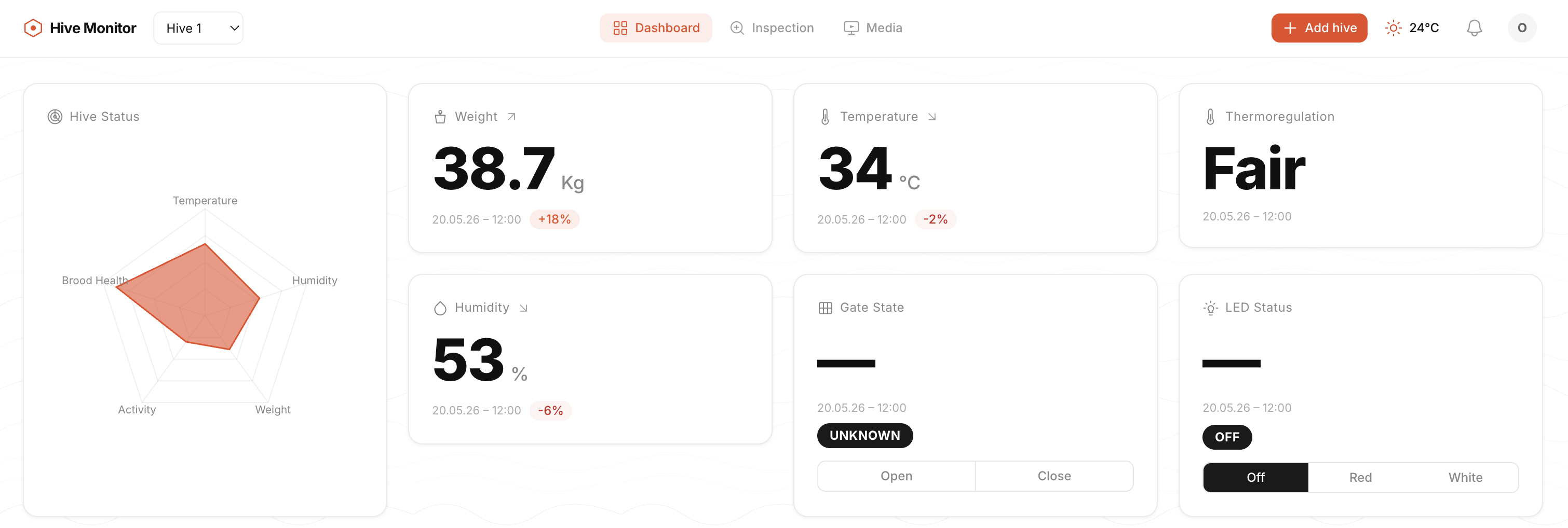
All subsystems connected and communicating — sensors, cameras, and controls running over PoE
The Pi runs a Python application that coordinates all subsystems:
- MJPEG HTTP server for live camera viewing (see Week 11)
- Sensor polling loop — reads each SHT45 via the multiplexer on a schedule
- Load cell reader — samples weight from HX711 at regular intervals
- Servo control — opens/closes the entrance on command
- GPIO LED control — turns the appropriate LED boards on when cameras activate, selecting white or red based on time of day
- Data logging — uploads sensor readings and weight data to a cloud dashboard
Hardware Configuration & Wiring
Pi 5 Specs
- Board: Raspberry Pi 5 Model B Rev 1.1 (8 GB)
- OS: Raspberry Pi OS 13 (Trixie), kernel 6.12.75 aarch64
- Power: Waveshare PoE HAT (F) via Ethernet — 802.3af/at
- Cameras: 2× IMX708 Wide (Camera Module 3 Wide) — Camera 0 on CSI port
i2c@88000, Camera 1 on CSI porti2c@80000 - Sensors: 3× SHT45 (temperature/humidity) via Adafruit PCA9548 I²C multiplexer
I²C Multiplexer Wiring (PCA9548)
| Pi GPIO | Mux Pin | Wire Color |
|---|---|---|
| 3V3 | VIN | Red |
| GND | GND | Black |
| GPIO 3 (SCL) | SCL | Yellow |
| GPIO 2 (SDA) | SDA | Blue |
SHT45 Sensor Channels
- Sensor 1 → Mux Channel 0
- Sensor 2 → Mux Channel 1
- Sensor 3 → Mux Channel 2
Configuration Steps
1. Enable I²C
I²C was disabled by default on a fresh Pi OS install:
sudo raspi-config nonint do_i2c 0
sudo reboot
Verify the multiplexer is detected at address 0x70:
sudo i2cdetect -y 1
# Should show 0x70 (PCA9548 mux)
2. Scan Sensors Through the Mux
This script loops through each mux channel and checks for an SHT45 (address 0x44):
for ch in 0 1 2 3 4 5 6 7; do
  sudo i2cset -y 1 0x70 $((1 << ch))
  result=$(sudo i2cdetect -y 1 | grep "44")
  if echo "$result" | grep -q "44"; then
    echo "Channel $ch: SHT45 found at 0x44"
  fi
done
sudo i2cset -y 1 0x70 0x00
3. Fan Control (Waveshare PoE HAT F)
The PoE HAT's onboard cooling fan is controlled via the thermal subsystem:
# Set fan speed (0-4)
echo 4 | sudo tee /sys/class/thermal/cooling_device0/cur_state

# Read RPM
cat /sys/devices/platform/cooling_fan/hwmon/hwmon2/fan1_input

# Reset to auto
echo 0 | sudo tee /sys/class/thermal/cooling_device0/cur_state
4. Camera Test
Quick capture test (use rpicam-* on Trixie, NOT libcamera-*):
rpicam-still --camera 0 -o /tmp/cam0.jpg --immediate -n
rpicam-still --camera 1 -o /tmp/cam1.jpg --immediate -n
Live Stream Server
The streaming server combines dual-camera MJPEG streaming with live sensor readings into a single web dashboard on port 8080:
- Streams both cameras at 1080p via MJPEG (using
rpicam-vid) - Reads all 3 SHT45 sensors every 2 seconds via the I²C multiplexer
- Serves a web dashboard with cameras + live sensor data
- Auto-starts on boot via cron
@reboot
Start Manually
nohup python3 ~/stream.py > /tmp/stream.log 2>&1 &Auto-Start on Boot
(crontab -l 2>/dev/null; echo "@reboot sleep 10 && python3 ~/stream.py > /tmp/stream.log 2>&1") | crontab -Server Endpoints
| Path | Description |
|---|---|
/ | Dashboard (cameras + sensors) |
/snap0 | Camera 0 JPEG snapshot |
/snap1 | Camera 1 JPEG snapshot |
/sensors | JSON: [{"temp": x, "hum": y}, ...] |
Next Steps
- Install
cloudflaredfor public access without router port forwarding - Set up a permanent Cloudflare Tunnel with a custom domain
- Integrate servo control endpoint into the web dashboard
- Add load cell readings to the
/sensorsendpoint
Related Weekly Work
- Week 1 — Final project proposal and initial sketches
- Week 2 — CAD of entrance housing and hive components
- Week 7 — CNC cut cedar roof
- Week 9 — SHT45 sensors and I²C multiplexer
- Week 10 — Custom LED boards (white + red)
- Week 11 — Dual-camera MJPEG streaming over network
- Final Project Page — Full documentation and BOM