This week focuses on modeling experimental objects and parts of my final project using 2D and 3D software, demonstrating various design processes, and learning proper file compression techniques.
Assignment Requirements
Task: Computer-Aided Design
Objective: Model (raster, vector, 2D, 3D, render, animate, simulate, …) a possible final project, compress your images and videos, and post a description with your design files on your class page.
Final Project Modeling: Pulse Jet Engine
For this week's assignment, I used my pulse jet engine concept from Week 1 as a test subject to explore different CAD and modeling software tools. This allowed me to evaluate various software options that I might use for my final project.
Design Approach
The software testing focused on:
Parametric 3D Modeling: Testing precision and dimensional control in different CAD packages
Organic Modeling: Exploring sculpting and artistic modeling capabilities
AI-Powered Generation: Experimenting with text-to-3D model creation
Physics Simulation: Testing animation and simulation capabilities
Software Testing and Evaluation
I tested multiple software packages for modeling, exploring both traditional CAD tools, web-based platforms, and AI-powered solutions. Each software was evaluated for its strengths, weaknesses, and suitability for different types of design work.
Primary Choice - My go-to software with extensive experience for parametric 3D modeling and engineering design. Available at autodesk.com/fusion-360 (free for personal/educational use). I've been using Fusion 360 for a while, so I didn't need a tutorial for this one — but Autodesk has great learning resources if you're getting started.
Pulse Jet Engine Design Process
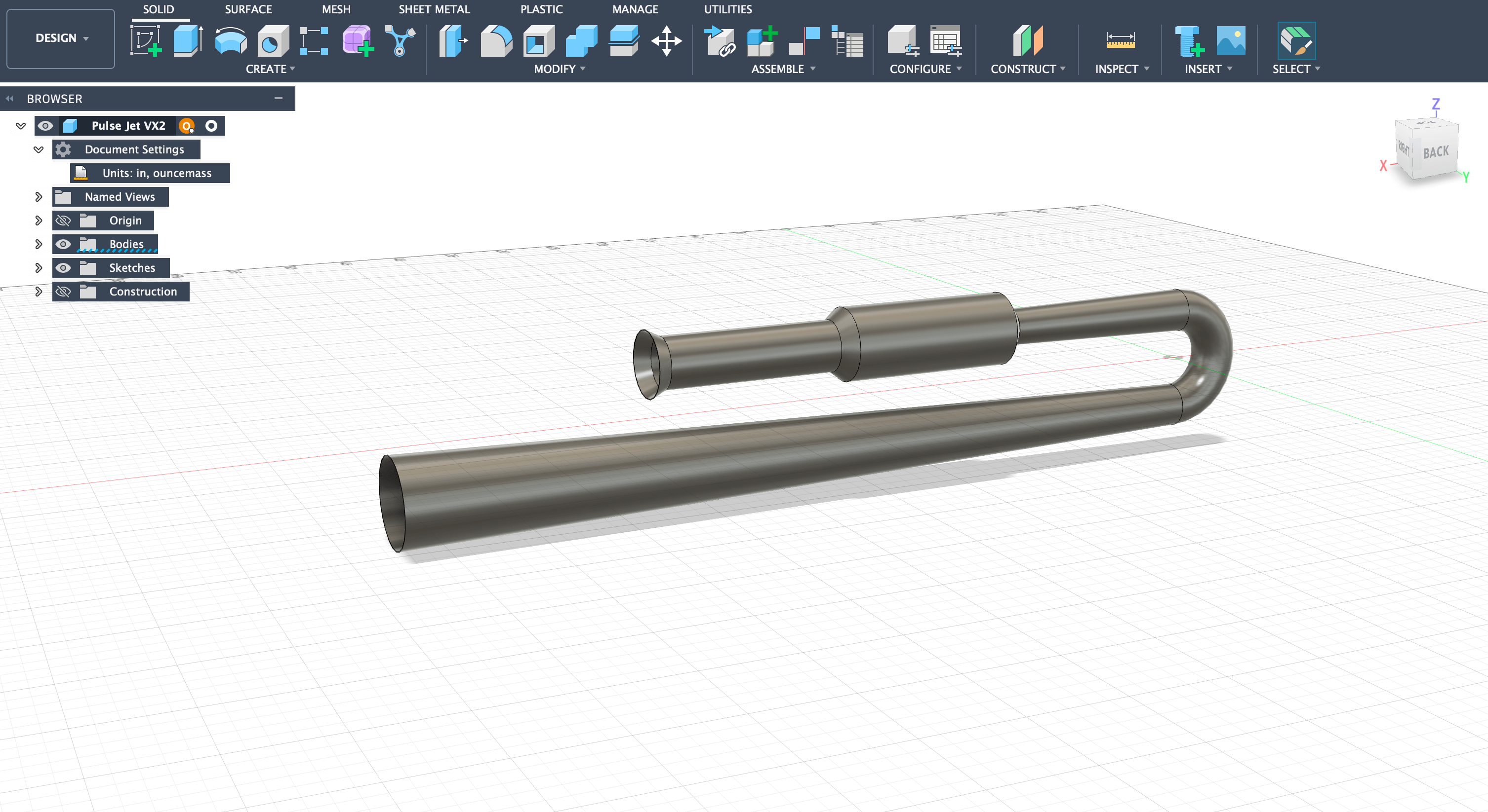
Using Fusion 360, I designed a Lockwood-Hiller inspired valveless pulse jet engine. The design uses 18-gauge stainless steel (0.0500 inches / 1.27 mm thickness) for most components and 16-gauge stainless steel (0.0625 inches / 1.59 mm thickness) for the combustion chamber due to higher heat exposure.
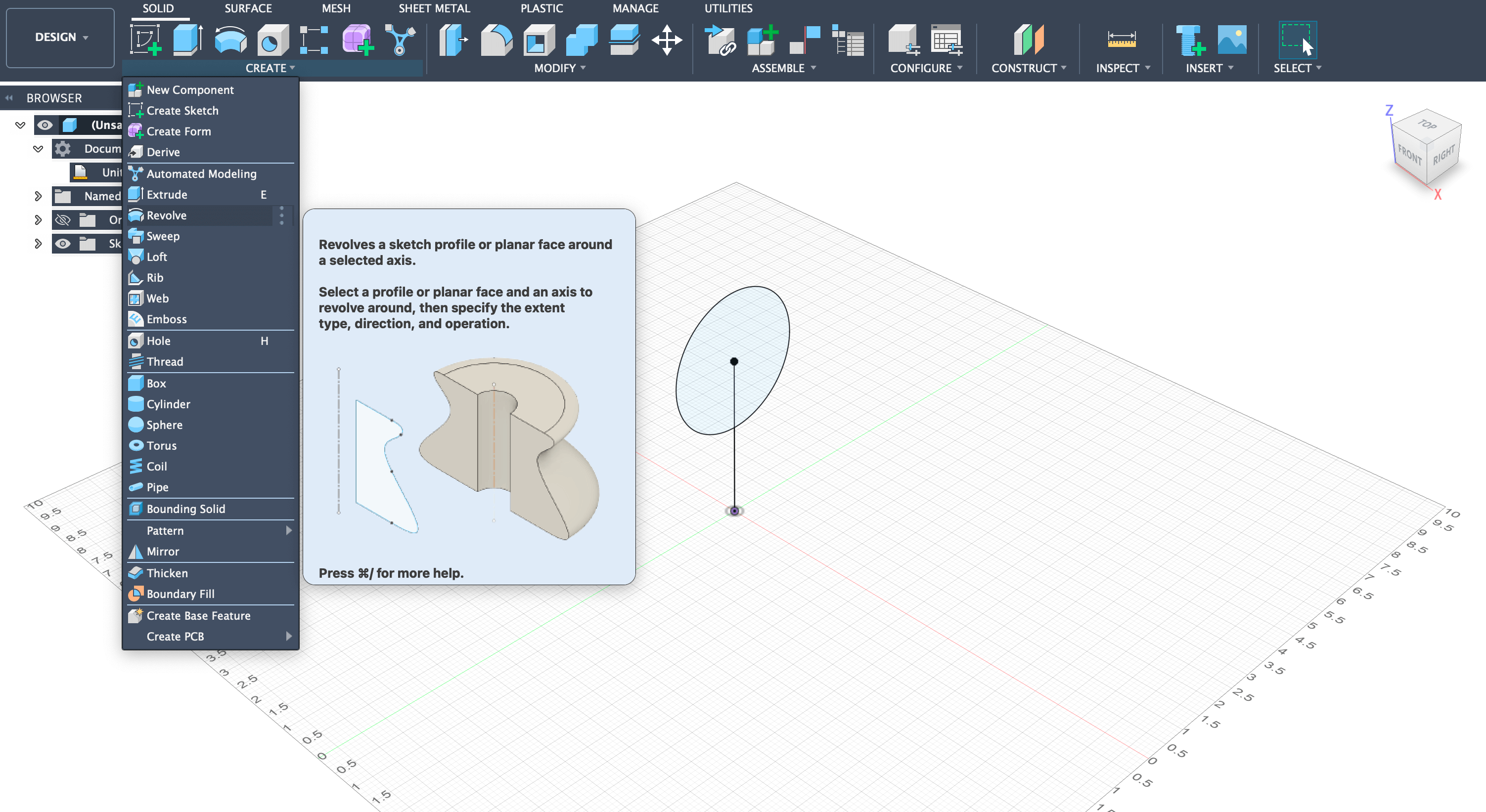
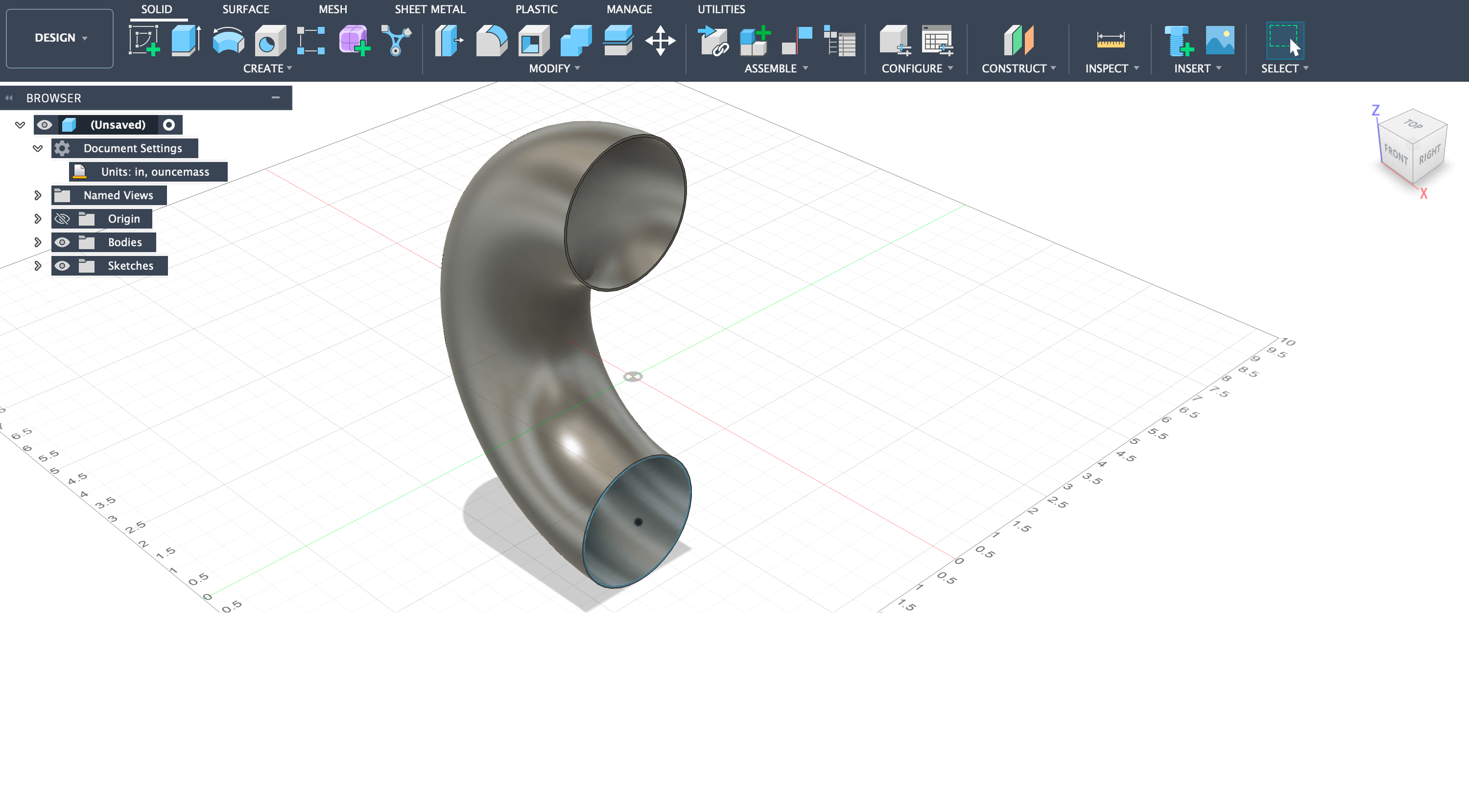
Step 1: Started by drawing a 3-inch diameter circle 2 inches away from the origin using the sketch tool.
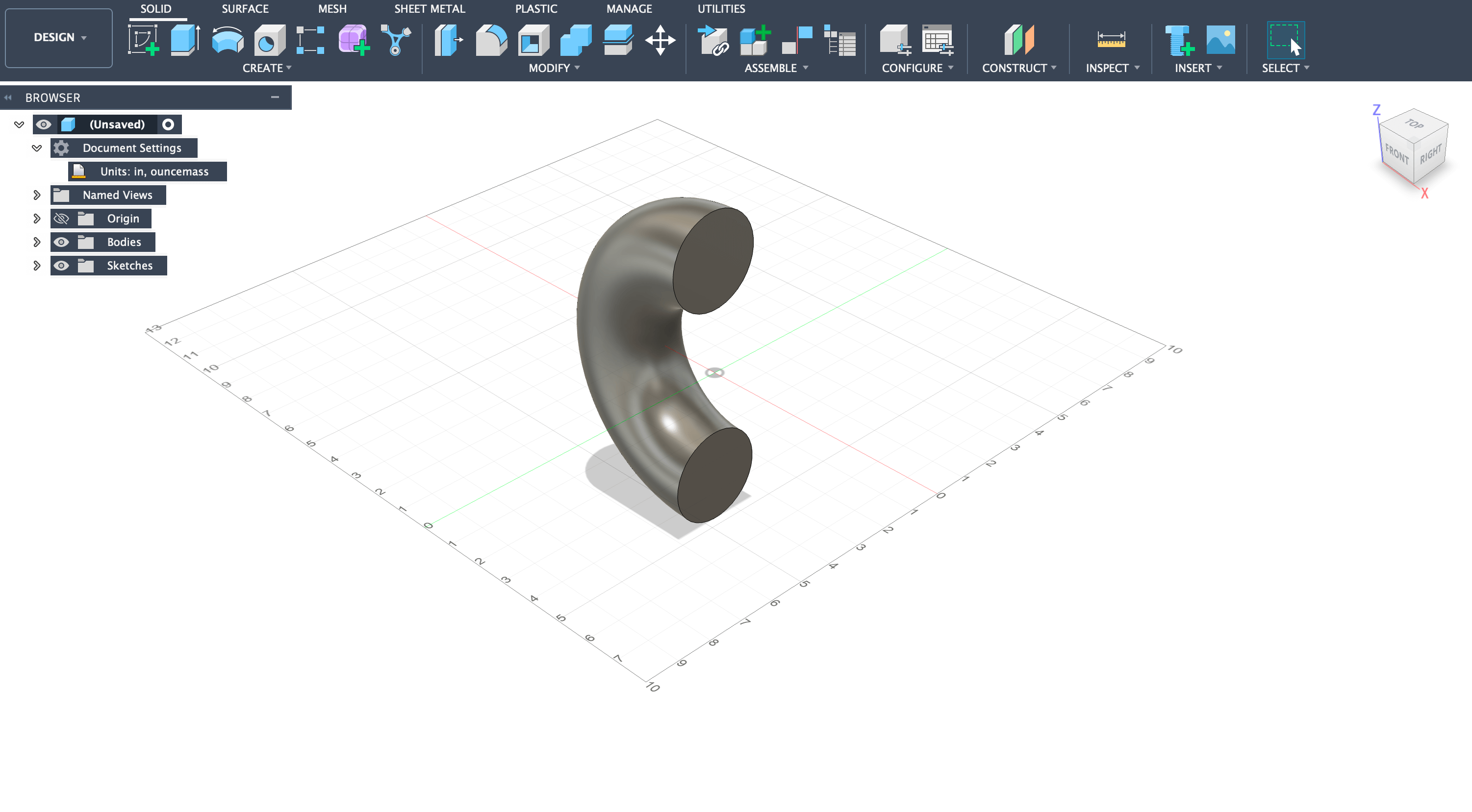
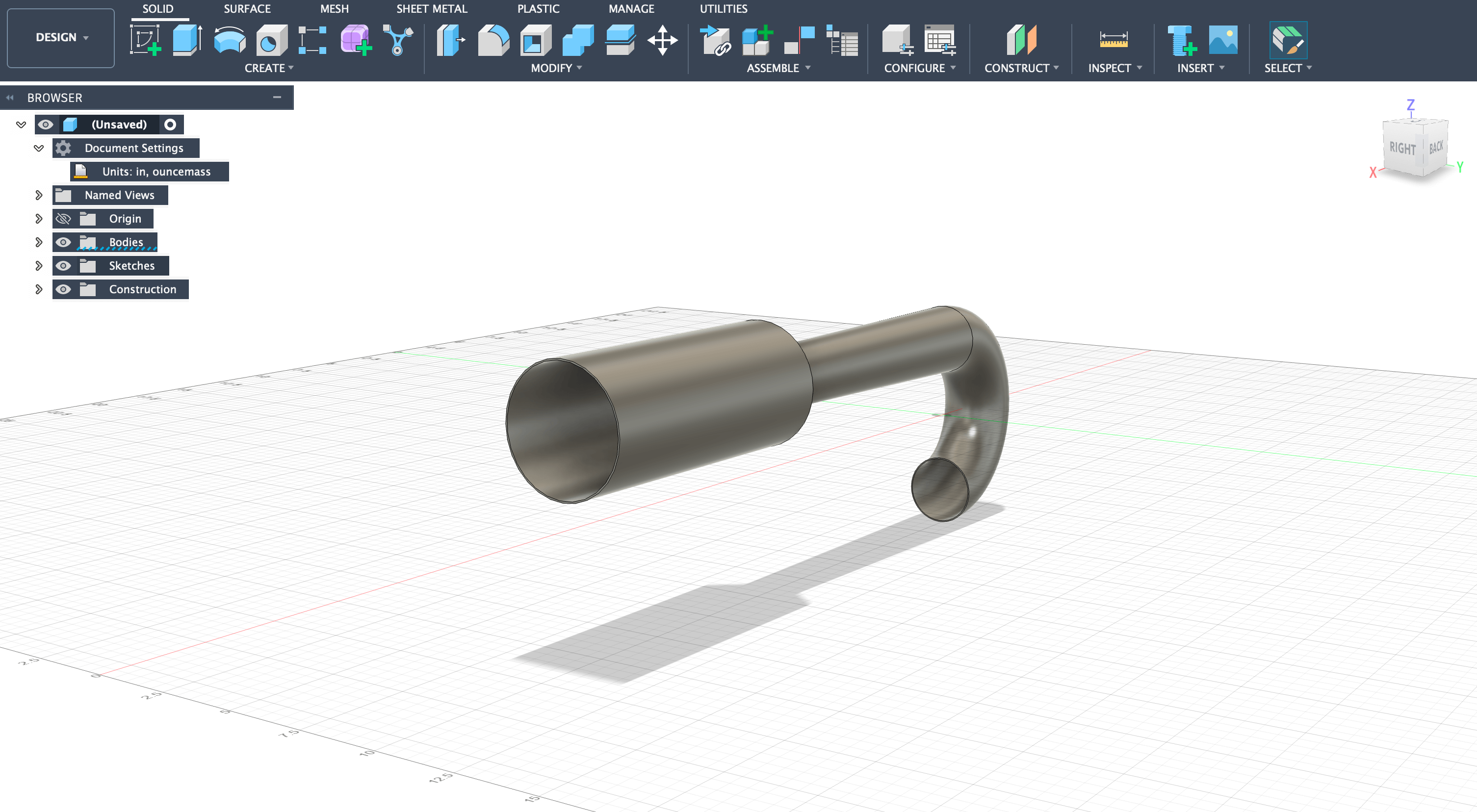
Step 2: Used the revolve tool to revolve the circle 180 degrees around the z-axis, creating the characteristic U-shaped bend.
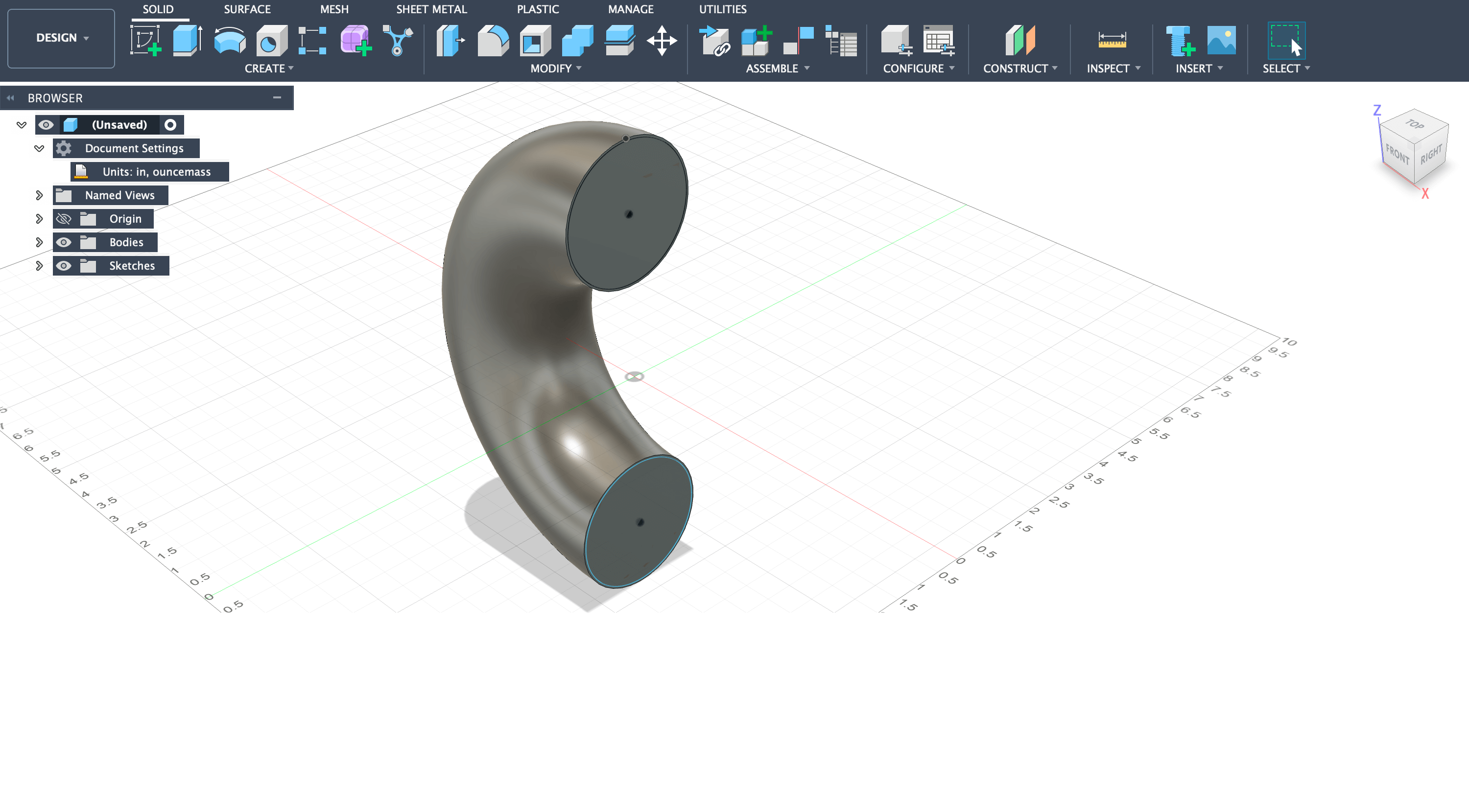
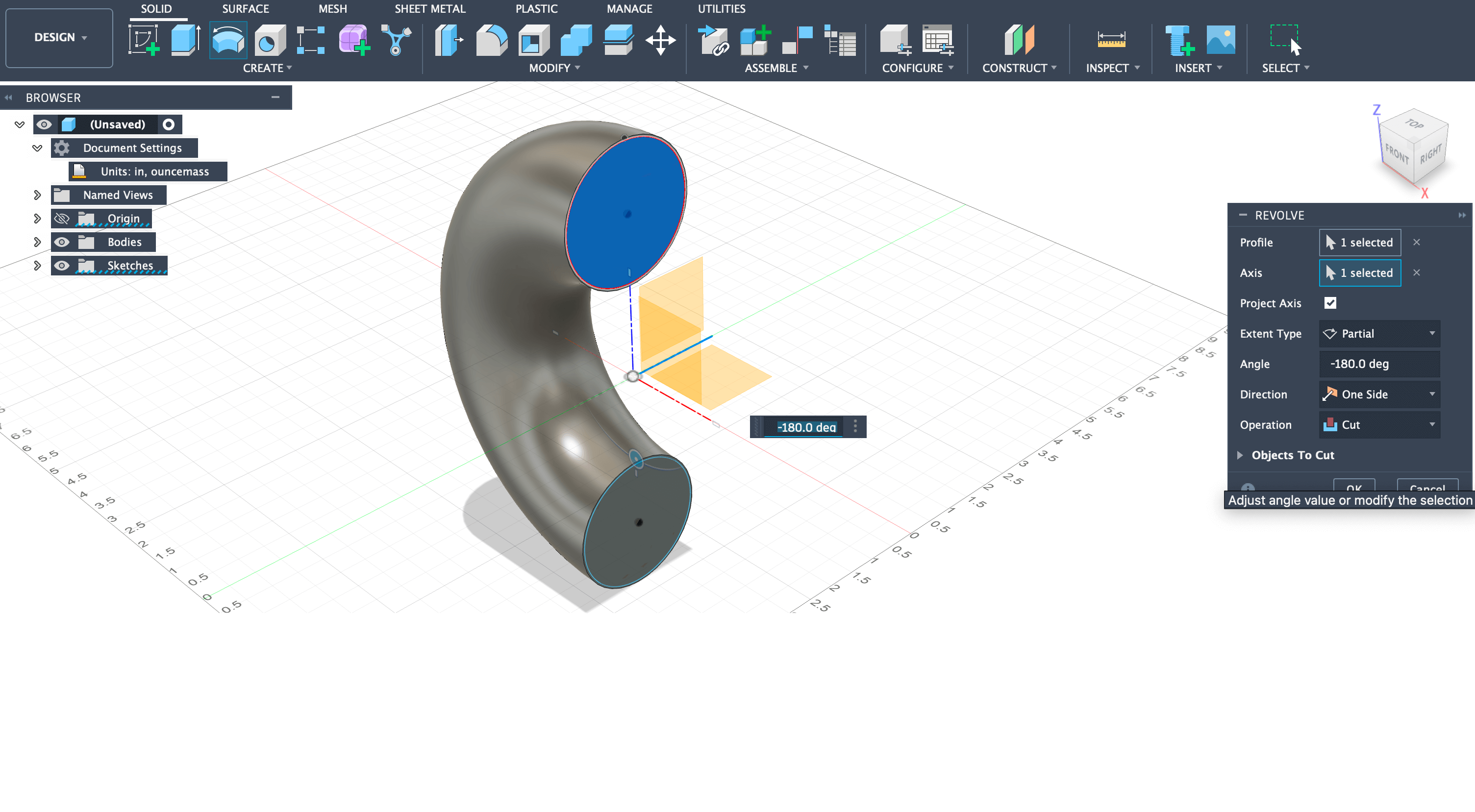
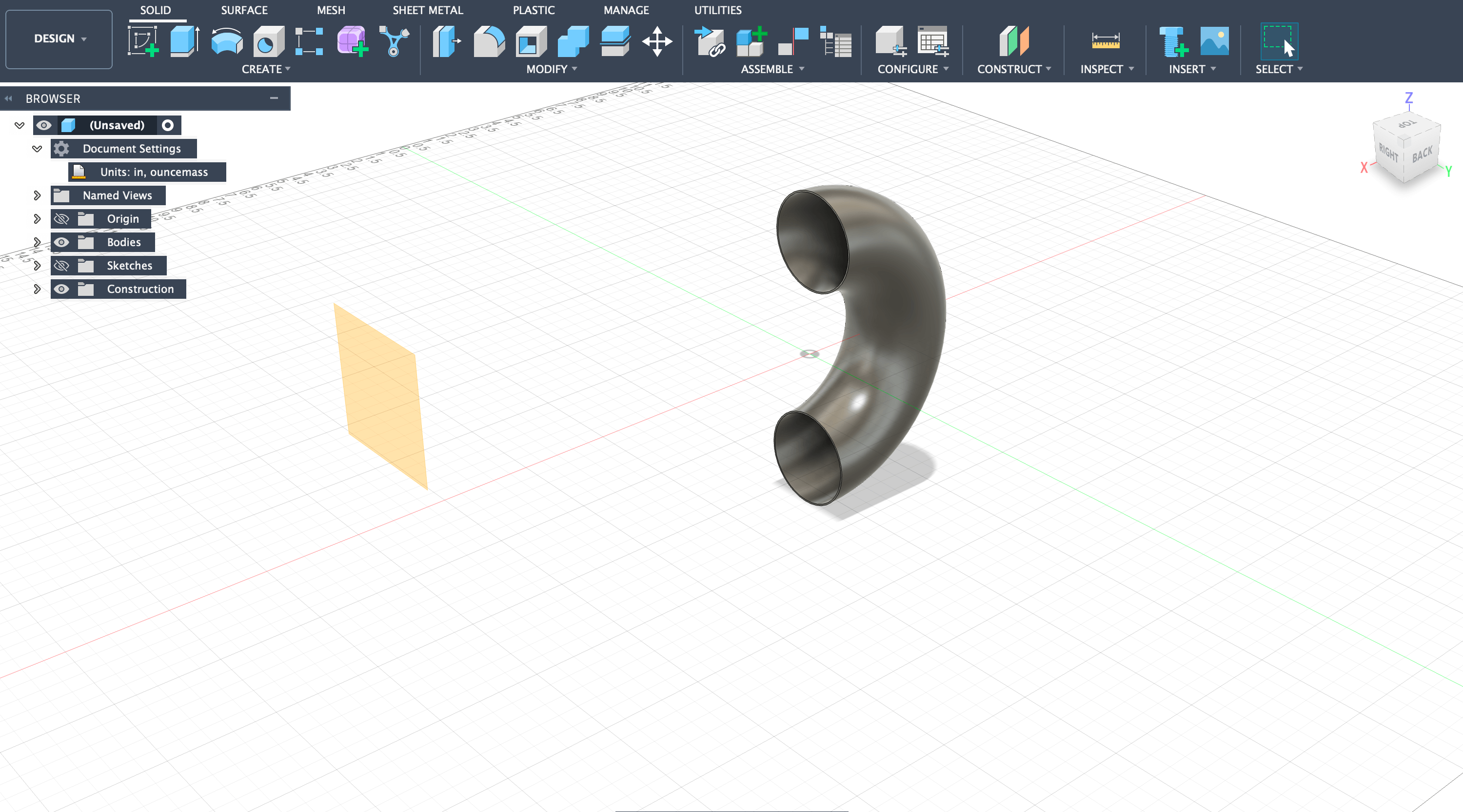
Step 3: Created a plane on the bend face and offset an inner circle by 0.0500 inches (18-gauge thickness), then used revolve tool set to cut to make the tube hollow.
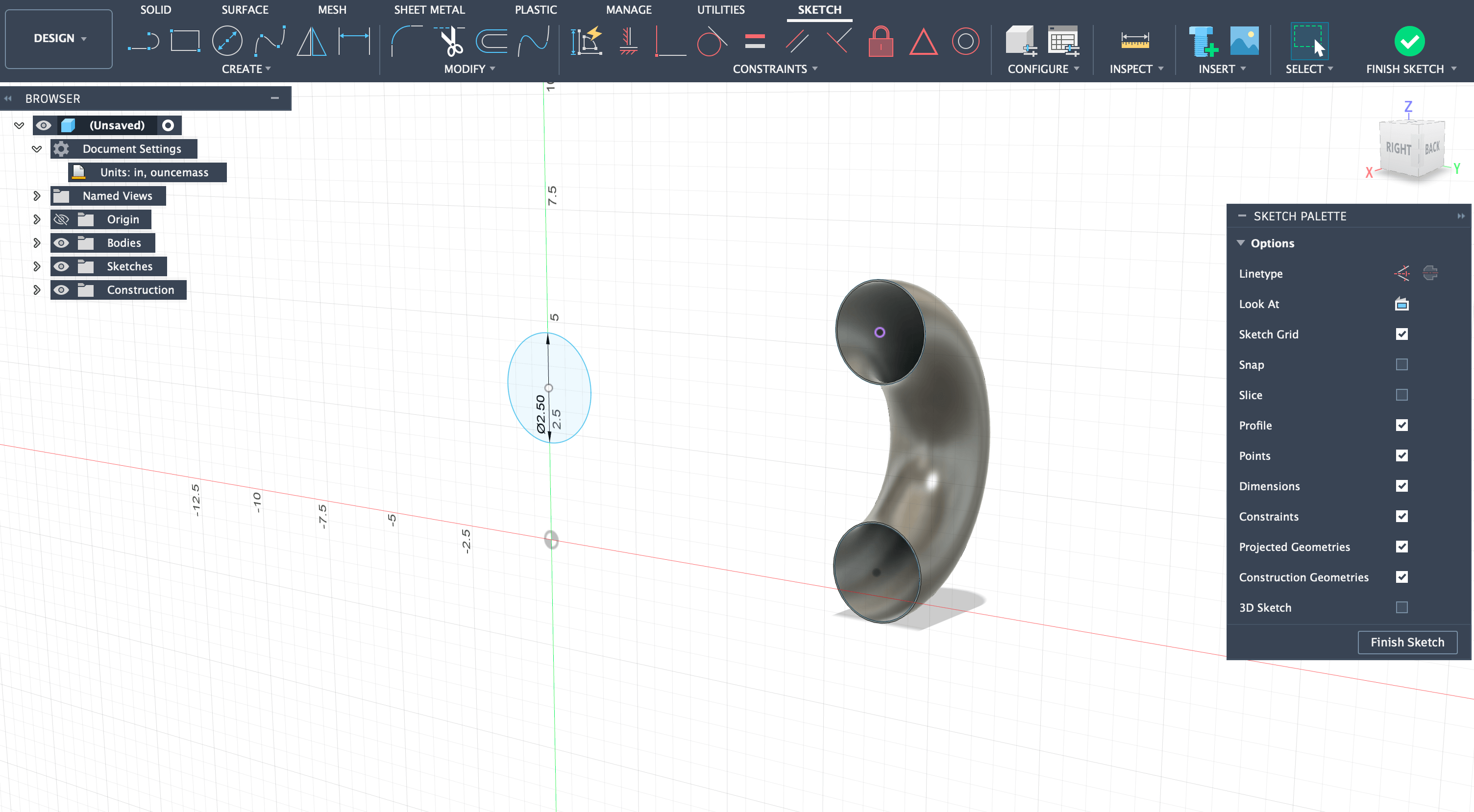
Step 4: Offset a plane 14 inches from the upper circle and created a 2.5-inch diameter circle for the transition cone.
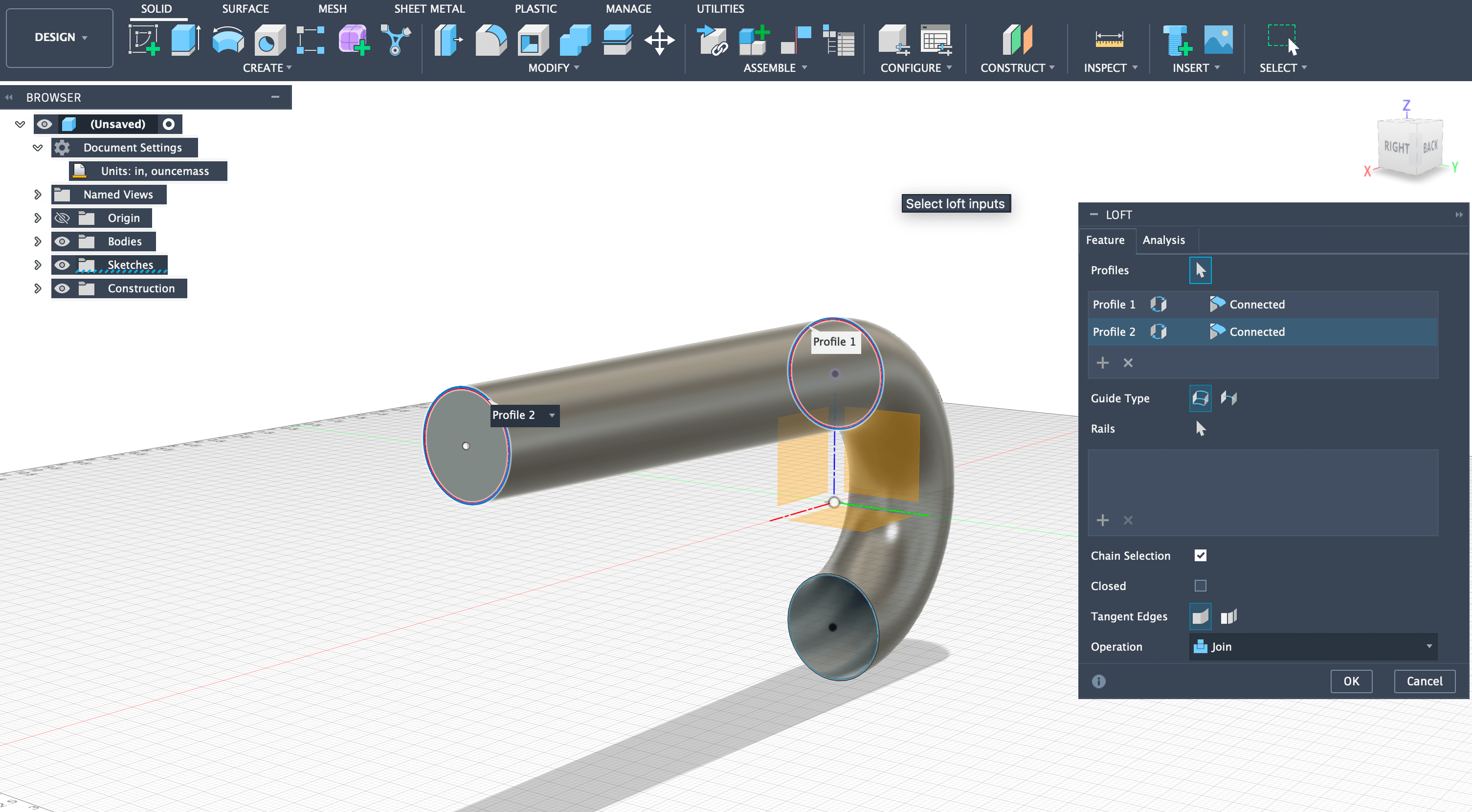
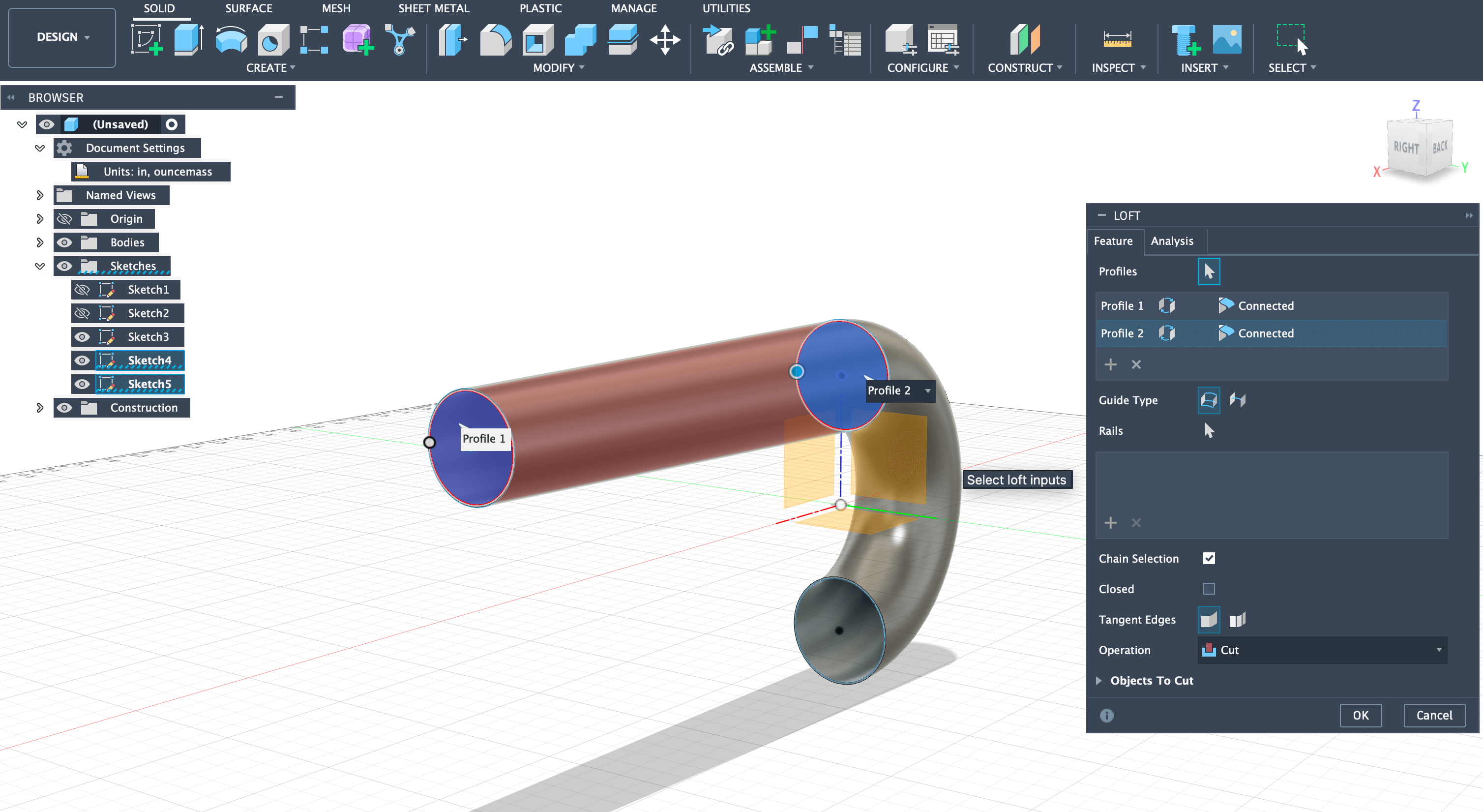
Step 5: Used the loft tool to connect the 3-inch upper tube to the 2.5-inch circle, creating a smooth transition.
Step 6: Created inner circle offset by 0.0500 inches and used loft tool set to cut to hollow out the cone section.
Combustion Chamber and Exhaust (Continued)
Continuing from Part 1, these steps complete the combustion chamber and exhaust sections of the pulse jet engine.
Step 7: Offset plane by 1 inch and created 5-inch diameter circle for combustion chamber expansion using loft tool.
Step 8: For the combustion chamber, used 16-gauge steel (0.0625 inches offset) due to higher heat exposure, then extruded 12 inches for total chamber length.
Step 9: Created transition from 5-inch combustion chamber to 3.5-inch intake/outlet using the same loft technique, then extruded 12-inch long pipe.
Step 10: Started lower exhaust section by offsetting plane 57.750 inches and drawing 6-inch diameter circle with 0.05-inch wall thickness (18-gauge).
Step 11: Added final cone section offset by 1 inch, expanding to 5-inch diameter to complete the basic pulse jet concept. Fuel injection system will be added later.
New Experience - Completely new to me, exploring animation and physics simulation capabilities.
How I Learned: I got my introduction to Blender from Angela Horstman, a Charlotte Latin Faculty Member and fellow Fab Academy student at the Charlotte lab. Angela gave a Blender intro session that covered the basics of the interface, navigation, and core modeling tools. From there, I also followed the official Blender tutorials to dig deeper into physics simulation.
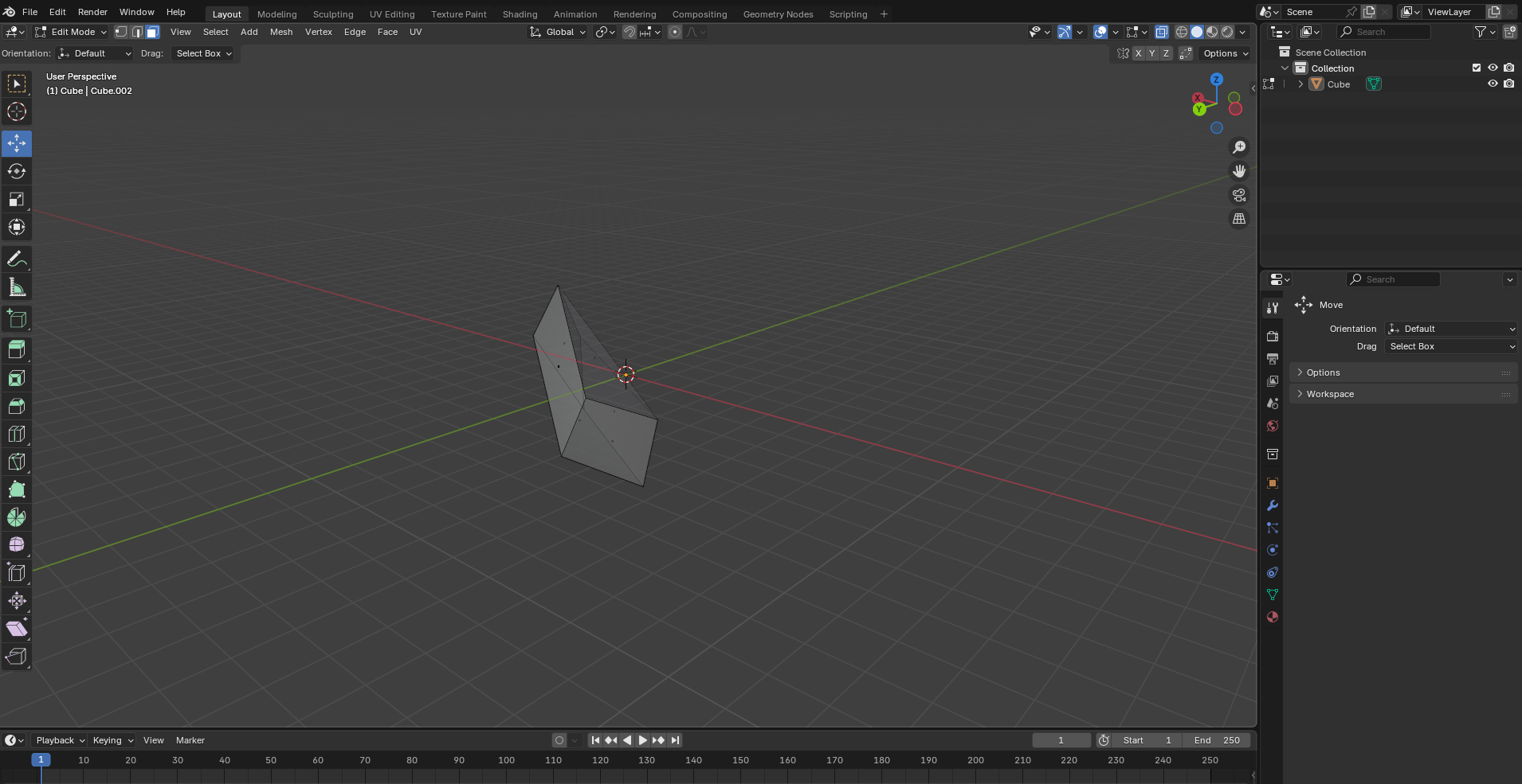
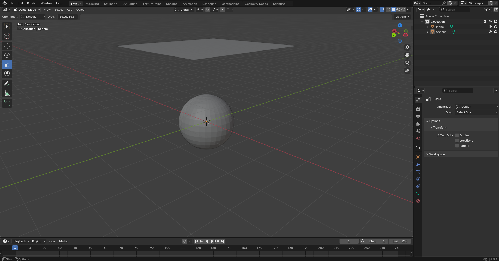
After Angela's intro session, I started by creating a simple model to get familiar with the software interface and basic modeling tools. This was purely experimental work to understand how Blender operates and to learn the fundamental controls.
My first model created in Blender while experimenting with the software and learning the basic tools and interface.
Cloth Physics Simulation
After getting comfortable with the basics, I moved on to testing Blender's physics simulation capabilities by creating a cloth simulation:
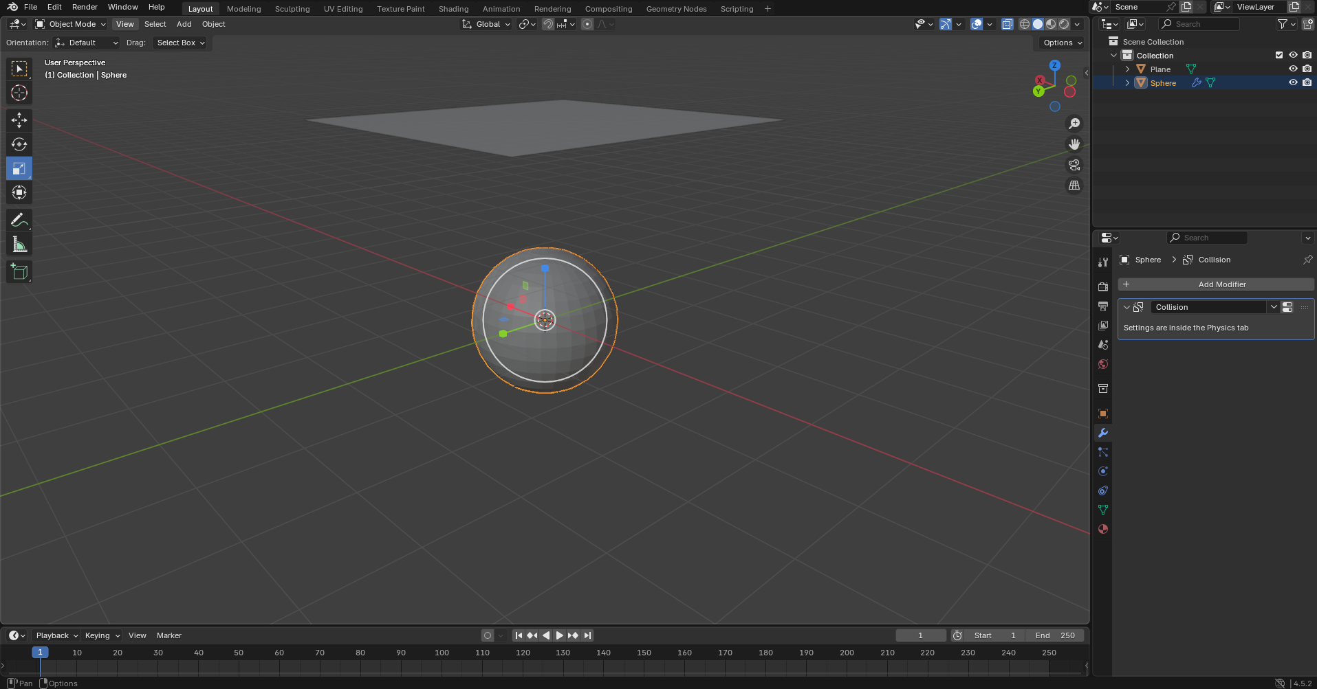
Created a mesh sphere to act as the ground/collision object.
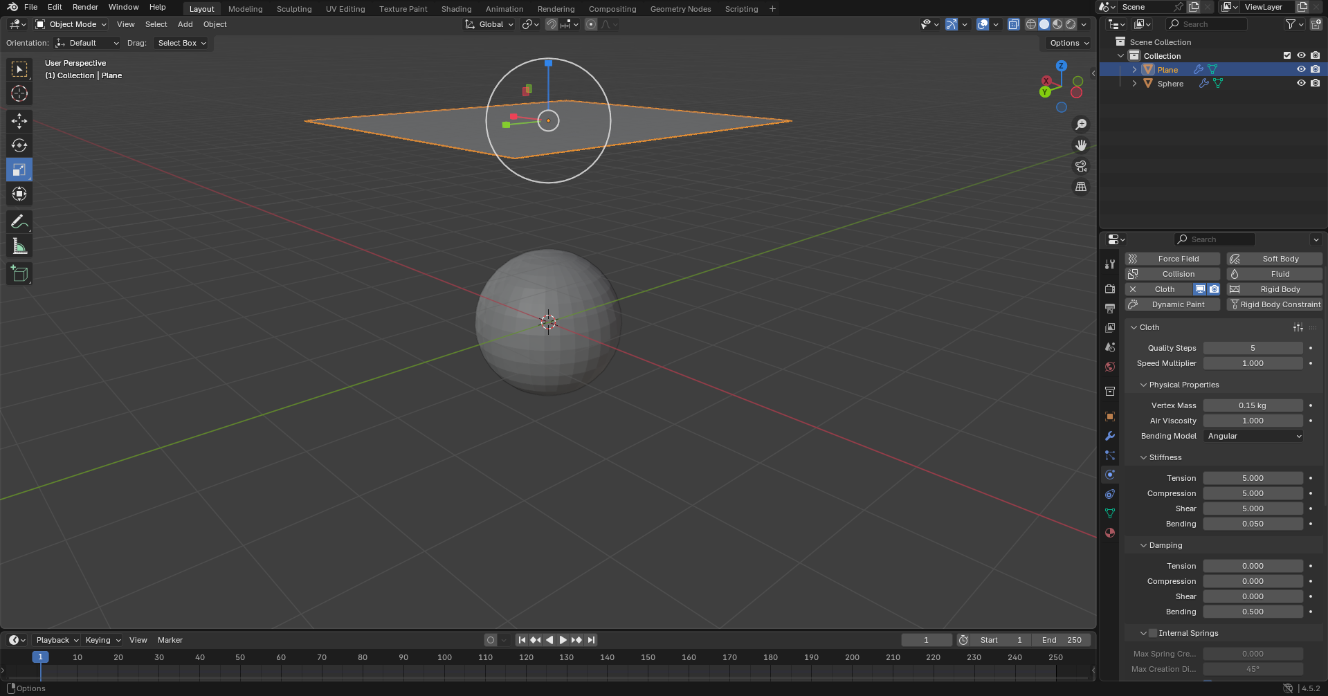
Added a plane, scaled it up, and moved it above the sphere. In Edit Mode, subdivided the plane 30-100 times to allow realistic deformation.
Added "Collision" physics to the sphere and "Cloth" properties to the plane in the Physics tab.
Simulation Video
Full cloth physics simulation showing realistic fabric behavior and collision detection.
Web-Based Tool - Online sculpting software that models like sculpting clay. You can try it directly in your browser at stephaneginier.com/sculptgl — no download or account needed.
Native File:SketchGLtest.sgl - This isn't the original face that I designed, but this is another test that I made because I did not save the other one and it doesn't save if you don't download it.
Face Sculpting Project
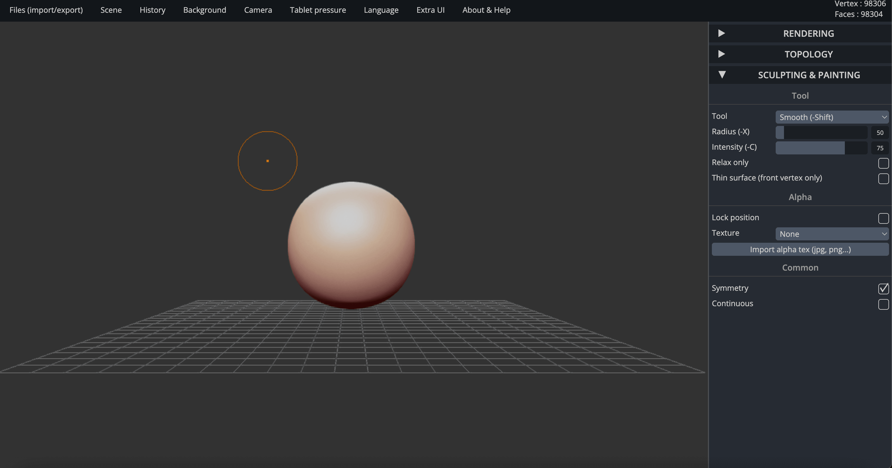
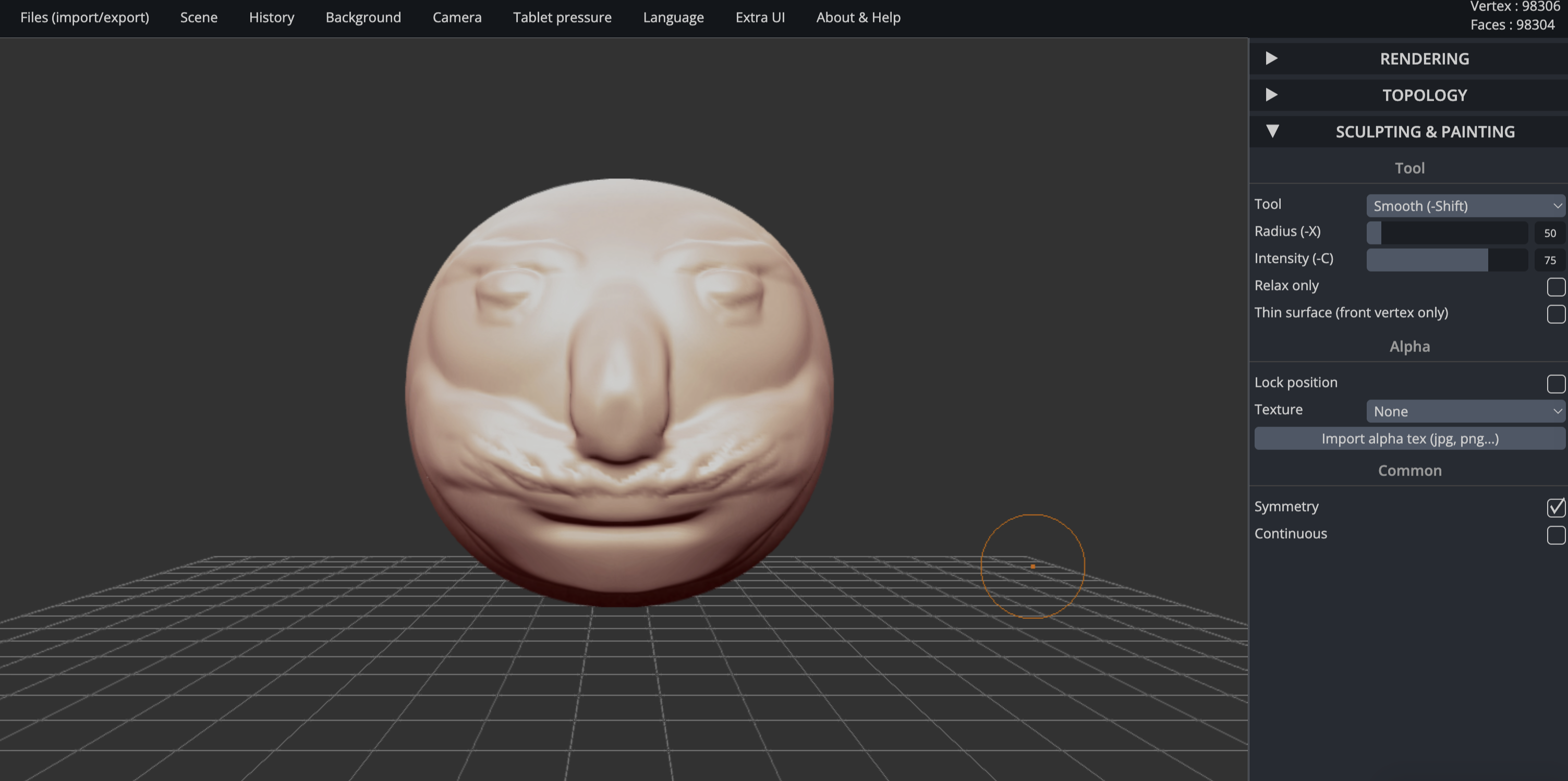
I created a face model using SculptGL to test its sculpting capabilities. This software was difficult to use for making precise geometric shapes - the clay-like modeling approach made it challenging to create square shapes and maintain dimensional accuracy.
SculptGL interface showing the sculpting process and tools available.
Final face model created using SculptGL's clay-like sculpting tools.
AI Platform - Web-based AI-powered 3D modeling platform that turns text prompts into 3D models supposedly in under a minute. You can try it at meshy.ai.
Native Files: I cannot include the native files because of the restrictions the service has on downloading them. The free tier only allows 10 downloads per month of Meshy 4 generated models.
AI 3D Generation Tests
I created an account and was given 300 credits to test this AI technology. I've never tested an AI that can do this sort of stuff before. The website is clean, easy to navigate, and shows examples of previously made models, including some that have been 3D printed.
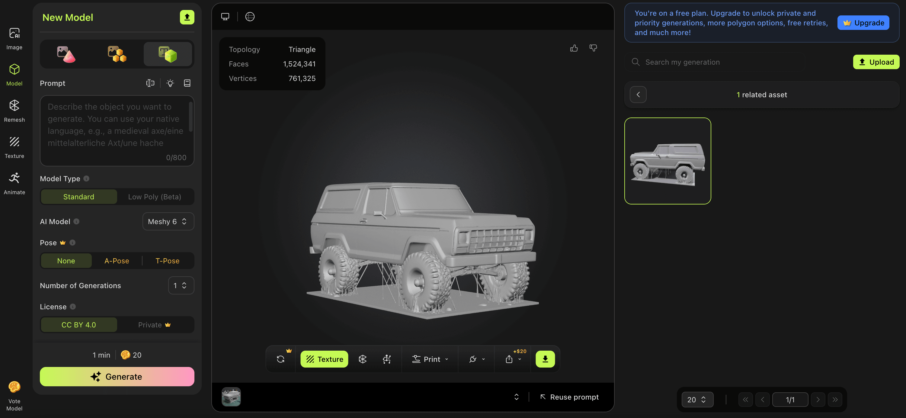
Test 1: 1979 Ford Bronco
Prompt: "Create a model of a 1979 Ford Bronco"
Time: 1:38.88 (not quite under a minute but still wicked quick)
Credits Used: 20
Result: Pretty good overall. You definitely would need some refining details if you wanted to 3D print, but for the speed, it's impressive.
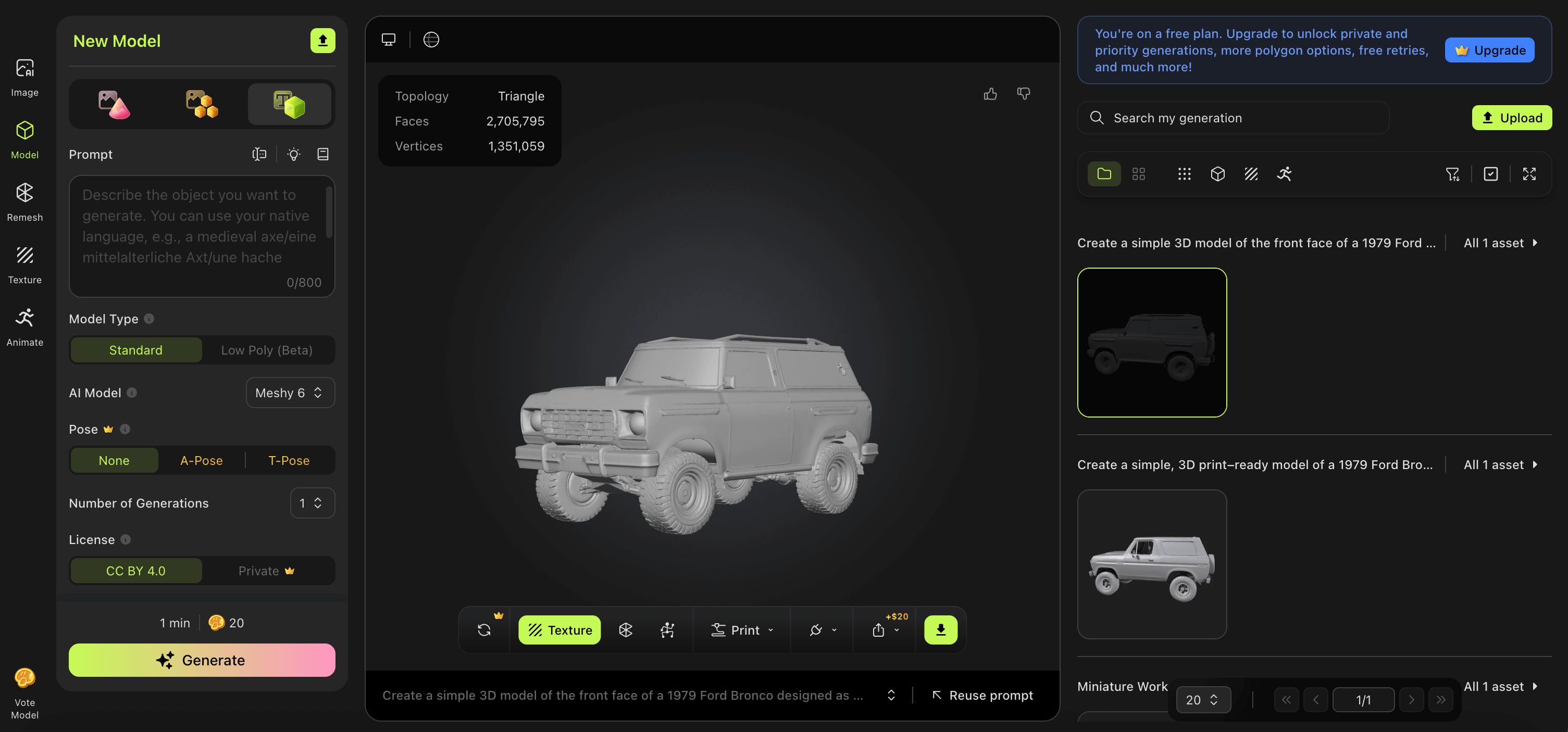
Test 2: Bronco Keychain
Prompt: "Create a simple 3D model of the front face of a 1979 Ford Bronco designed as a keychain. Focus only on the front view (grille, headlights, hood, bumper), with no full vehicle body."
Time: 2:31.93 (took a little longer, which is interesting)
Result: Didn't really understand the prompt - created another full truck model instead of just the front face. The design wasn't consistent with the original truck but showed less stringiness and was cleaner overall. It mixed different Bronco generations: the '78-'79 (2nd gen) with later versions like the '80-'86 (3rd gen) and maybe a bit of the '87-'91 (4th gen), which is weird.
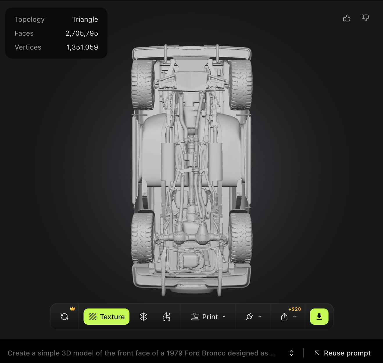
Interesting Detail: The AI added some weird mechanics on the underside, including what looks like some sort of dual rear differential. I can't blame it though - this is a pretty complex design it chose to make, and in the amount of time it did it, it's pretty well done.
Conclusion: The one problem is on the free model of this software you can only download models made by Meshy 4 - only 10 per month - but you can still generate with the other models. It feels like a waste and is probably designed to get people hooked, then at the end of the process they find out they can't download their model. That said, it was cool to see where this technology is going and how fast it's developing and getting better. I don't see the use of it for anything with specific dimensions, but I'm sure you could probably get it pretty close by scaling it in a slicer if you're planning on 3D printing. I think it's more developed for art and making 3D characters - if that's what you're interested in, I would definitely recommend you try it out.
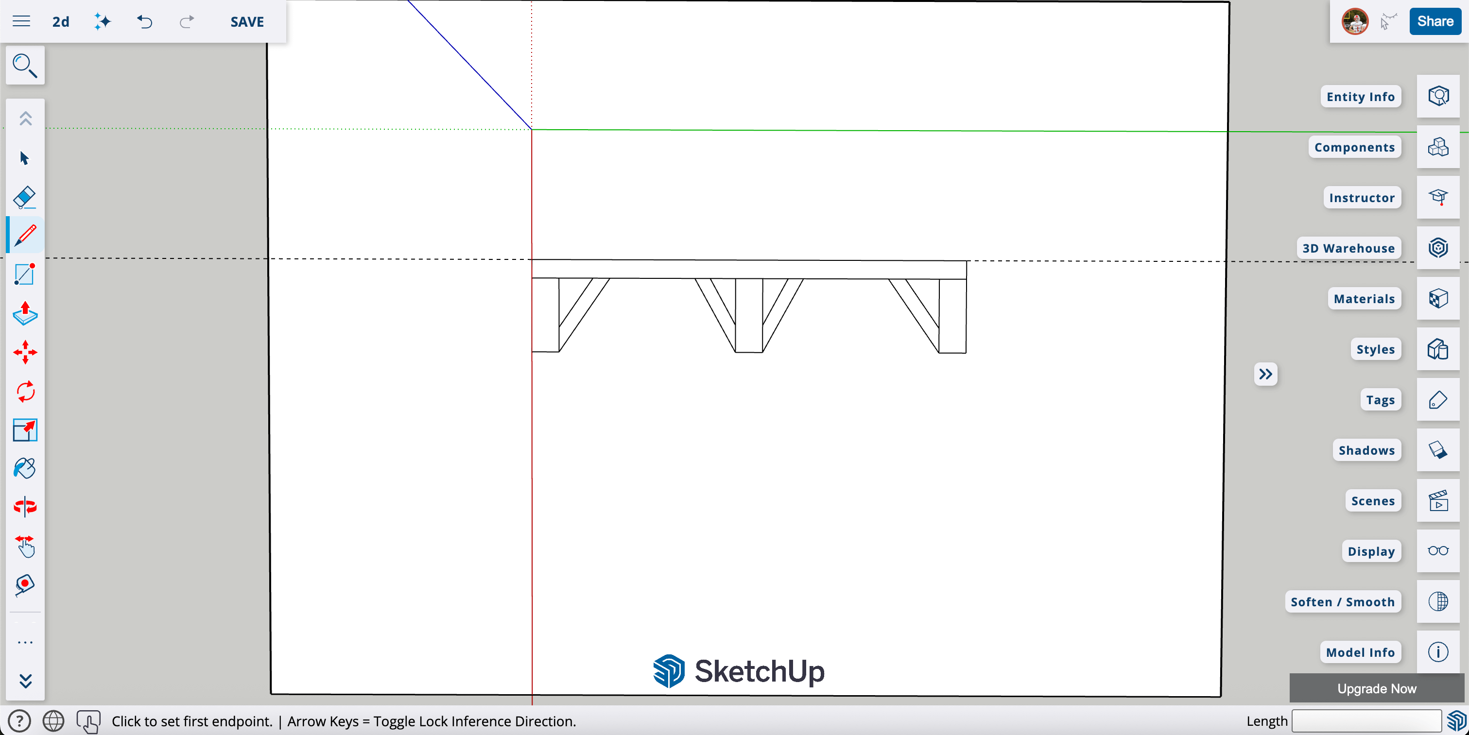
Web-Based Software - Free web-based software that can be used for both 2D and 3D modeling, though it excels more at 2D modeling. SketchUp has a helpful learning portal with video tutorials.
Native File:SketchUp2D.skp - SketchUp native file with table design
Table Design Project
I designed a table using SketchUp's free web-based software. You can access it at sketchup.trimble.com - just click "Start Modeling" and create an account (which you have to do).
Table design created in SketchUp. It's not the best, but it took me some time to understand and learn the controls.
SketchUp Experience
I actually liked using SketchUp - it's quite similar to Fusion 360 in some ways. While I would prefer to do my 2D designs in Fusion, I really liked this software. The only things are it didn't have many ways to edit like adding arcs or fillets to corners, it was harder to set measurements, and I couldn't get it to change from cm to inches even though I selected the setting and saved it. The camera slips a lot while working which is really annoying. If you want to change a dimension later, you often have to remodel the object rather than simply editing a parameter, which is also annoying. The midpoint selection is also buggy - when you select the midpoint of a line, sometimes it doesn't actually select the exact point, and this happens often.
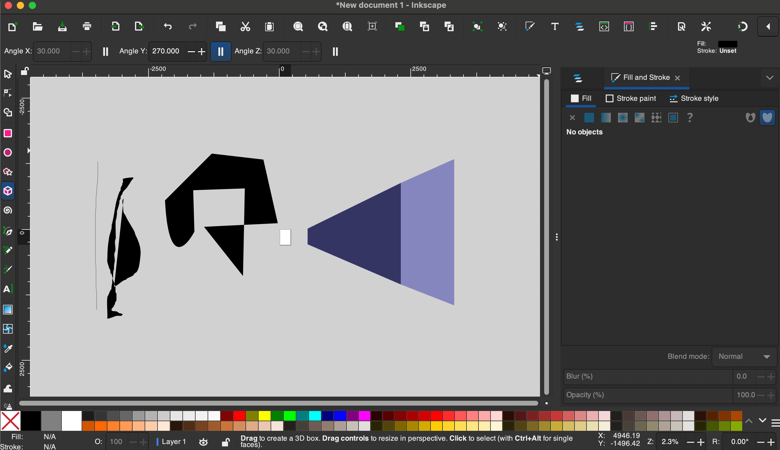
Free Vector Graphics Editor - One of my favorite online drawing tools that I have tried for 2D design work. Download it at inkscape.org.
Inkscape Experience
Inkscape is a powerful, free, open-source vector graphics editor that's great for creating 2D designs, illustrations, and technical drawings. I really enjoyed testing this software and found it to be surprisingly capable for a free tool. I followed some of the official Inkscape tutorials to get started.
Inkscape interface showing the vector drawing tools and workspace.
Pros and Cons
Pros
Completely free and open-source
Powerful vector editing tools
Clean, intuitive interface
Great for technical drawings
Supports many file formats
Active community and tutorials
Cons
Learning curve for advanced features
Can be slower with complex designs
Not as polished as paid alternatives
Some tools less intuitive than Adobe
My Thoughts
While Inkscape is excellent for digital 2D design work, I would still rather just grab a pen and pencil if I was to make a 2D design from scratch. There's something about the tactile nature of traditional drawing that's hard to replace. That said, for refining designs, creating technical drawings, or working with vector graphics, Inkscape is fantastic - especially considering it's completely free. The fact that it doesn't cost anything makes it accessible to everyone, which is a huge advantage for students and hobbyists.
Final Project Modeling
I changed my final project from the pulse jet engine to a Smart Beehive system. The pulse jet work shown in this week's Fusion 360 section was completed before the project change and demonstrates the CAD skills learned during this assignment.
All of my final project modeling and CAD work is documented on the Final Project page under the CAD & Build tab. That includes the full 3D design of the Smart Beehive enclosure, component layout, and construction details — all done in Fusion 360. I keep all final project modeling centralized there so it stays up to date as the design evolves.
Image & Video Compression
Compressing images and videos is important for keeping page load times fast and reducing bandwidth. Here's the process I use for all documentation images and videos on this site:
Image Compression Process
I use two free online tools depending on the file type:
TinyPNG — Works great for PNG and JPEG files. You just drag and drop your images onto the page, it compresses them, and you download the result. It typically reduces file size by 50–80% with no visible quality loss.
imagecompressor.com — Another drag-and-drop tool. This one lets you adjust the compression quality with a slider so you can preview the result before downloading. I usually keep it around 80–90% quality.
My workflow: after taking a screenshot or photo, I go to one of these sites, upload the image, download the compressed version, and then add it to my project's images/ folder. It only takes a few seconds per image and makes a big difference in page performance.
Video Compression
For videos, I keep file sizes manageable by recording at reasonable resolutions and trimming clips to only show what's needed. Most of my documentation videos are short clips under 30 seconds. If a video is too large, I'll reduce the resolution or trim it further before adding it to the site.
Design Files Repository
File Organization
All original design files are organized and available for download:
3D Models & Native Files
📦 Pulse Jet Engine VX2 Native Fusion 360 file with complete parametric model Download .f3d file