V1 — First Cut (Plywood Test)
Our lab uses a ShopBot Alpha CNC router. For the first version of the roof I used plywood to test the design before committing to the nice cedar. The roof uses dowel joints — the holes on the sloped gable sections are cut on the CNC, with 3 dowels per corner at a ¼" hole size.
VCarve CAD/CAM Workflow
I designed all the roof and inner cover parts as 2D sketches in Fusion 360, then exported them as DXF files. From there, I used VCarve Pro to set up the toolpaths for the ShopBot. Here's the workflow I followed:
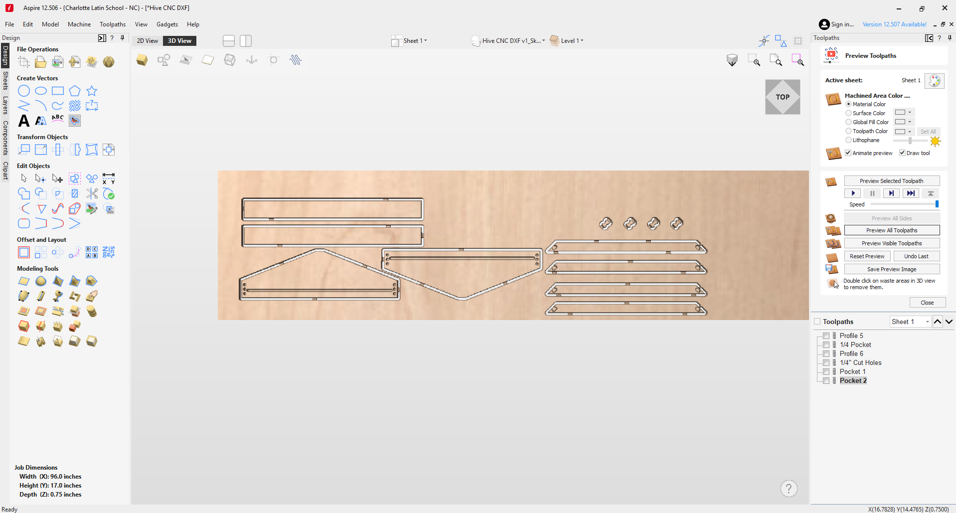
VCarve Pro — V1 roof and inner cover toolpath setup
- Design in Fusion 360 (2D): I drew all the roof parts as 2D sketches in Fusion 360 — the gable sides with the angled slope, the rectangular side boards, and the dowel hole positions. Everything was designed as flat 2D profiles since the CNC cuts from sheet material.
- Export DXF: Exported the 2D profiles as a DXF file from Fusion 360.
- Import into VCarve: Opened VCarve and created a new project. Set the material dimensions to match my plywood sheet (for V1) or cedar panel (for V2), and set the material thickness. Then imported the DXF file — all the vectors came in as 2D geometry on the workspace.
- Set up the material: In the Job Setup panel, I entered the stock dimensions (X, Y, Z), set the Z-zero to the top of the material, and set the XY datum to the bottom-left corner of the stock. This tells VCarve where the origin is relative to the material on the ShopBot bed.
- Organize vectors: After import, I checked that all the vectors were closed and properly positioned. Some vectors needed to be joined or cleaned up — open vectors won't generate toolpaths correctly. I also made sure the dowel hole circles were separate from the profile cuts so I could assign different toolpaths to them.
- Profile toolpaths (outside cuts): For the outer profiles of each roof part, I created a Profile toolpath set to cut on the outside of the vector. This ensures the finished part matches the designed dimensions. I used a ¼" bit, set the cut depth to the full material thickness, and added tabs to hold the parts in place during the final pass so they don't shift or fly off the bed.
- Pocket/drill toolpaths (dowel holes): For the ¼" dowel holes on the gable sides, I created a separate Drilling or Pocket toolpath. I selected the hole vectors and set the depth to match the dowel insertion depth (not all the way through). Used the same ¼" bit since the holes match the bit diameter — this makes them a simple plunge cut.
- Speeds and feeds: I set the feeds and speeds in VCarve for each material:
Plywood (V1):- Feed rate: 100 in/min (2540 mm/min)
- Plunge rate: 50 in/min
- Spindle speed: 18,000 RPM
- Pass depth: 0.125" (half the bit diameter per pass)
- Feed rate: 80 in/min (2032 mm/min) — reduced because cedar is softer and can tear/fuzz if pushed too fast
- Plunge rate: 40 in/min
- Spindle speed: 16,000 RPM — slightly lower to reduce heat and burning on the softer wood
- Pass depth: 0.1" — shallower passes for a cleaner cut in the soft grain
- Preview and export: VCarve has a 3D preview that simulates the cut — I used this to verify that all the toolpaths looked correct and nothing was being cut in the wrong direction or at the wrong depth. Once satisfied, I exported the toolpaths as ShopBot (.sbp) files and loaded them onto the machine.
For V2, I went through the same process but with the updated DXF that had the corrected dimensions (shorter side boards, reduced gable height, angled ends). The VCarve project files (.crv3d) for both versions are available in the Design Files section below.
Cutting beehive roof V1 on the ShopBot Alpha CNC router
End Mill — Specs & Vendor
For all cuts (profile and pocket/drill), I used a ¼" (6.35mm) 2-flute downcut spiral end mill. The downcut geometry pushes chips downward into the cut, which gives a much cleaner top surface — no tearout or fuzz on the visible face of the wood. This is especially important for the cedar where surface quality matters.
- Diameter: ¼" (6.35mm)
- Flutes: 2
- Cut type: Downcut spiral
- Cutting length: 1"
- Shank: ¼"
- Material: Solid carbide
- Vendor: Amana Tool 46225-K — ¼" Downcut Spiral
Tab Setup
Tabs are small bridges of material left uncut that hold the part in place during the final pass — without them, the part would come loose and potentially shift or fly off the bed, ruining the cut or causing a safety hazard. In VCarve, I added tabs to all profile (outside cut) toolpaths:
- Tab width: 0.25" (¼")
- Tab height: 0.06" — just enough to hold the part without being difficult to remove
- Placement: Automatic with manual adjustment — VCarve distributes them evenly around the profile, but I moved some to avoid corners and areas where they'd be hard to sand off
- Quantity: 3–4 tabs per part depending on size (larger gable sides got 4, smaller side boards got 3)
After cutting, I used a flush-cut saw to remove the tabs, then sanded the spots smooth. On the cedar parts I was extra careful not to gouge the surface.
Installing the Bit in the ShopBot
The ShopBot Alpha in our lab has an automatic tool changer (ATC). The machine handles bit swaps entirely on its own — no manual intervention needed during a job:
- Assign tools in the software — in VCarve, each toolpath is assigned a tool number that corresponds to a bit already loaded in the machine's tool rack
- Automatic swap — when the job runs, the spindle moves to the tool rack, picks up the correct tool holder, and the drawbar clamps it in place. When it needs a different tool, it returns the current one to its slot and picks up the next one — all automatically
- Z-zero — after picking up a tool, the machine touches off on the Z-touch plate to set the Z-origin for that specific bit length
The whole process is hands-off. You just set up the toolpaths in VCarve with the correct tool numbers, hit run, and the ShopBot takes care of grabbing, swapping, and zeroing the bits as needed.
V1 Test Fit
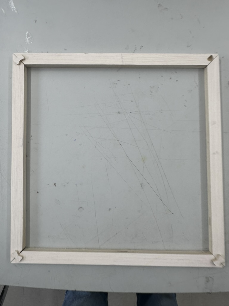
I test fit the roof on an empty hive that I have ready for this upcoming season and noticed that it's about ¼" too long — you can see the gap by looking at the bottom edge in the photo below.
Roof V1 test fit — about ¼" too long, visible gap at the bottom edge
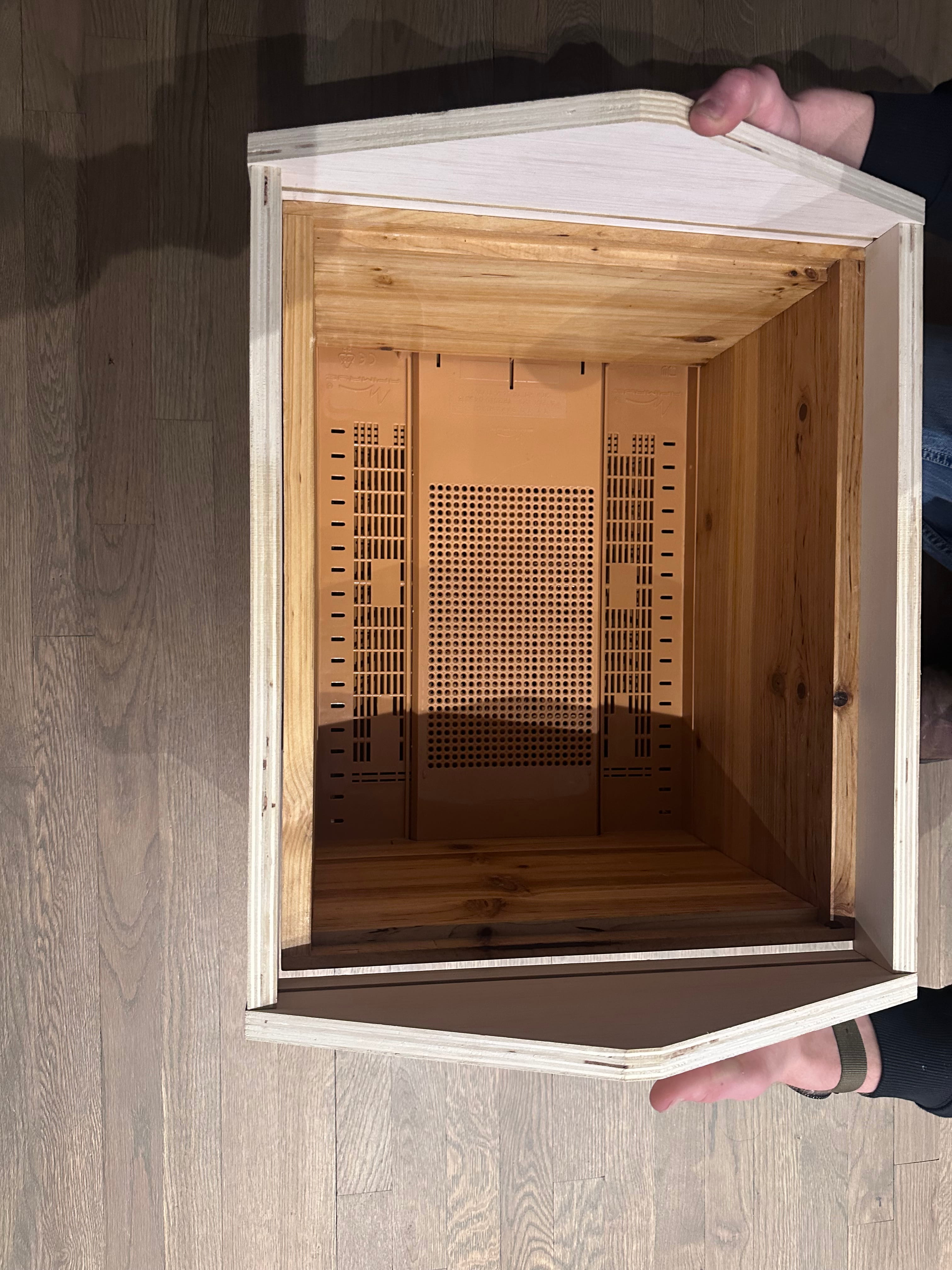
After noticing the overhang, I decided to take actual measurements of the hive box I'm fitting to. This box has been sanded and finished, so it's probably a little smaller than a brand new one would be — but only by a small amount.
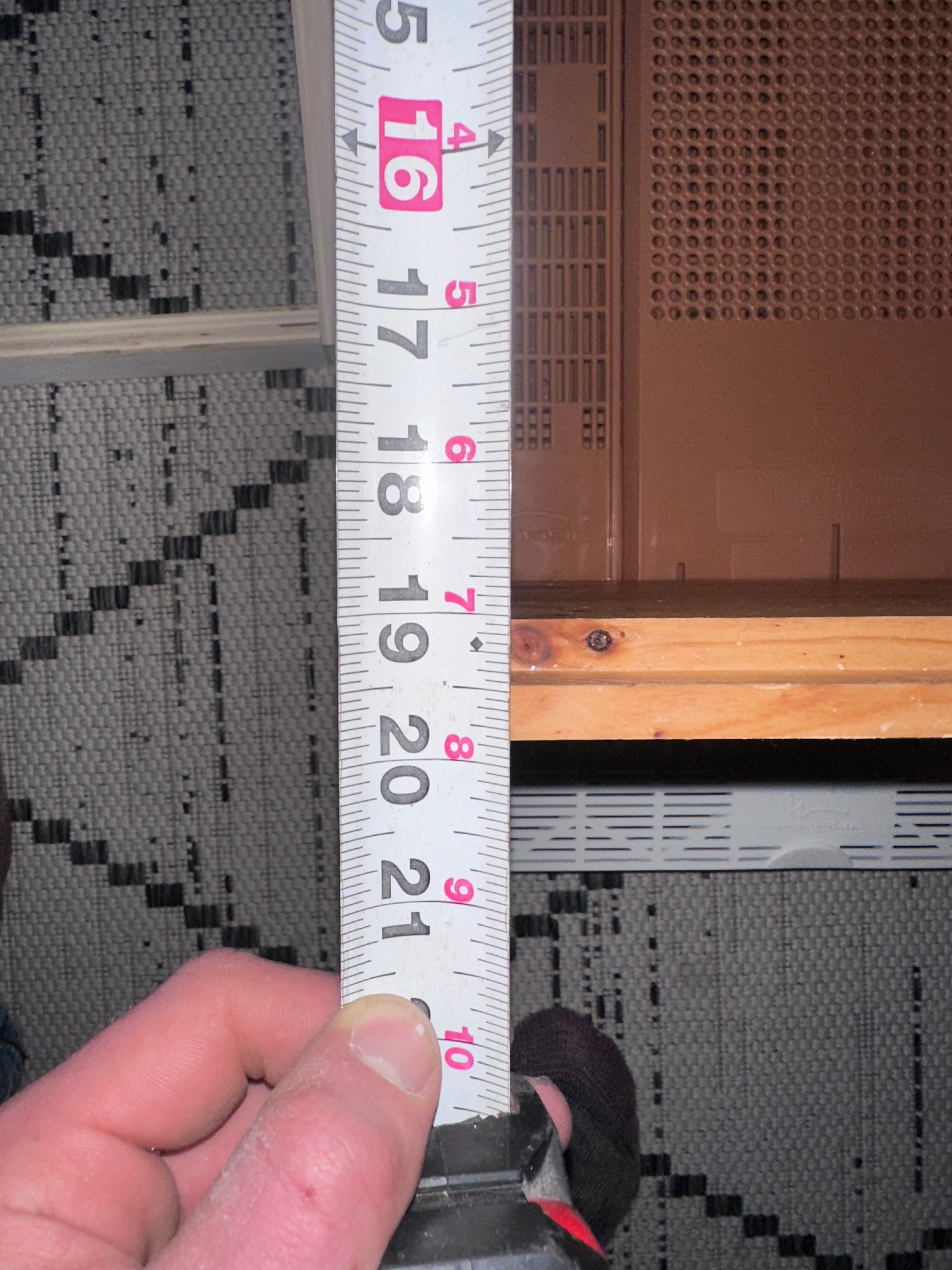
Measuring the existing hive box — width
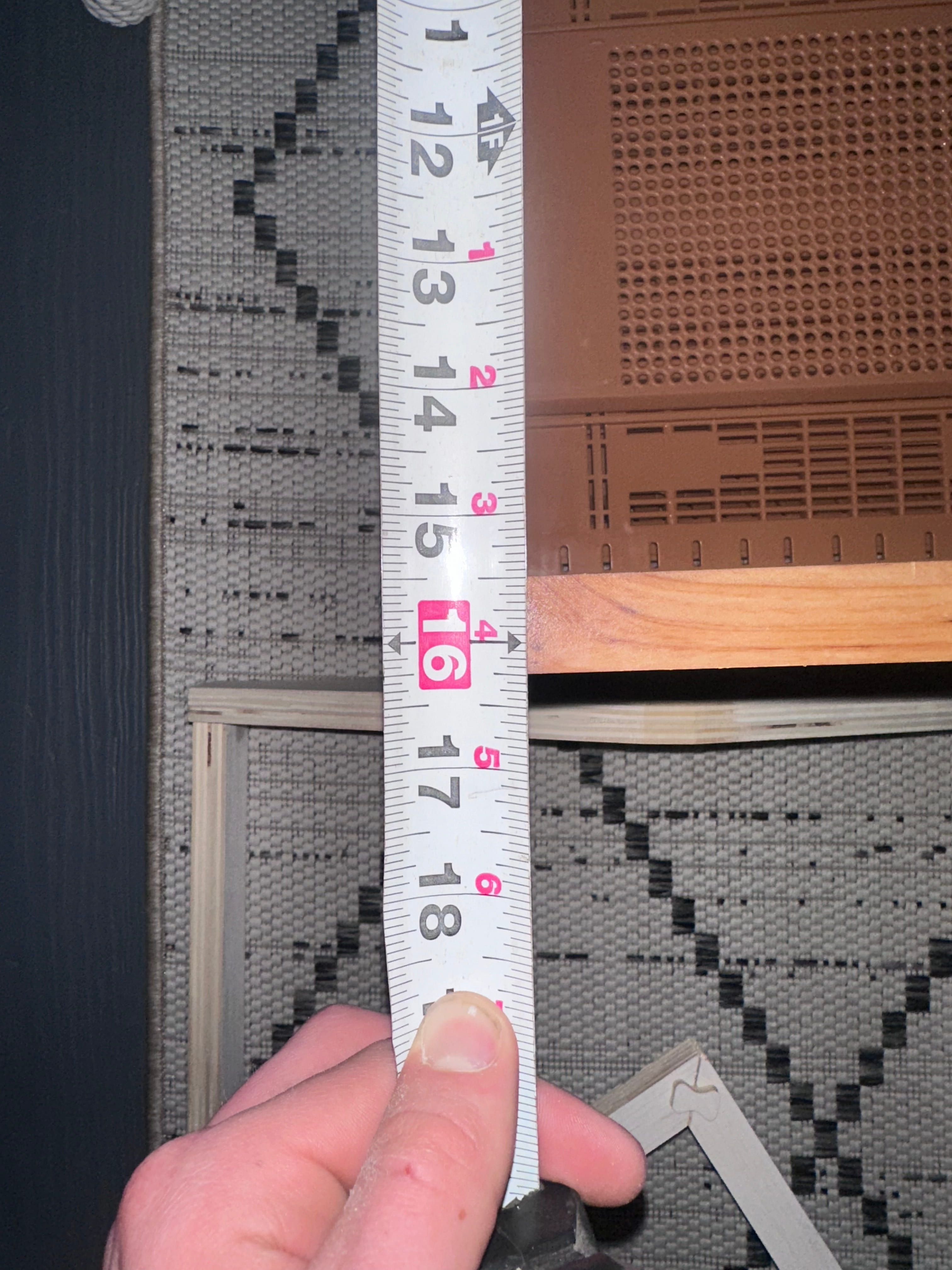
Measuring the existing hive box — length
Sourcing Cedar
After testing with plywood, it was time to move to the real material. I bought 6 cedar boards from Lowe's at $18.27 each. Usually, select cedar boards with no knots are very expensive, so instead of paying the premium I decided to go in person and inspect each board individually, only buying the ones with very little to no knots. Knots are weak points in the wood — they can crack, fall out over time, or create gaps that let moisture and pests into the hive.
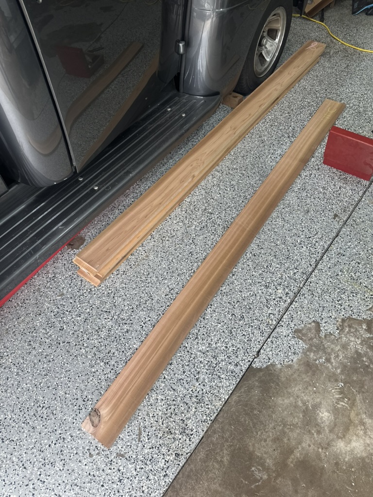
Hand-selected cedar boards with minimal knots
I measured the thickness at about 0.85", and I only need 0.75" for standard hive wall thickness. This is good because when I join the boards I'll need to plane them, so the extra material gives me room to work with.
Joining the Boards — Tongue & Groove
I needed a way to join these boards into wider panels and I didn't want to go out and buy a very expensive joiner tool. Instead, I bought a router bit from Rockler — specifically the 1-7/8" D × 1/4" H × 1/4" Shank Rockler 3 Wing Slotting Cutters Bit for $54.99. Much better than a $260 joining tool. I used this bit to make tongue and groove joints — cutting a centered tongue on one board edge and a matching groove on the adjacent board so they interlock.
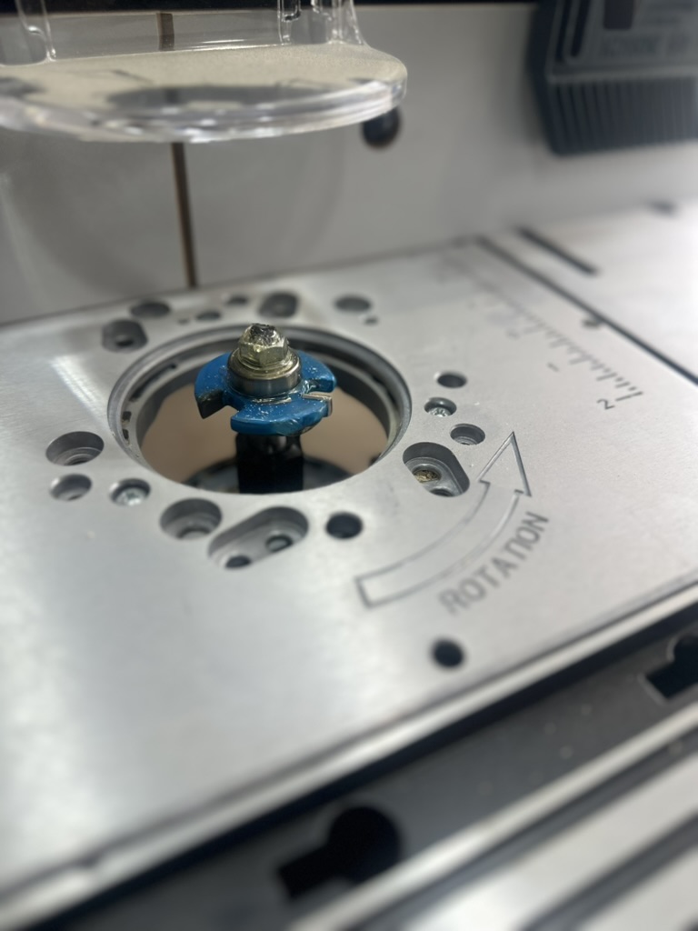
Rockler 3 Wing Slotting Cutter bit attached to the router table
I attached the bit to my router table and cut the boards. It took lots of trial and error to get the fit right, but thankfully I didn't ruin any of the boards.
Tongue and groove joint cut into the cedar boards
Glue-Up & Planing
The next step was to glue the boards up. I used Titebond III wood glue, which is waterproof and rated for outdoor use — important for a beehive that sits outside year-round. I could only do one board at a time since I didn't have a lot of clamps.
After they were all glued up, the boards had a small but noticeable bump where they were joined. I anticipated this — first I used a hand planer to remove the bulk of the material, also clearing off glue residue as I went. After getting it as good as I could by hand, the boards obviously weren't perfectly flat, so I brought them to the lab and used the thickness planer.
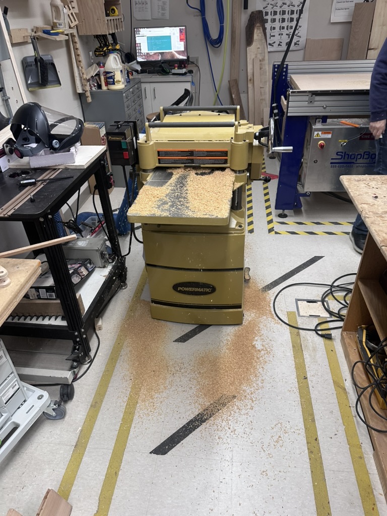
Running the joined cedar panels through the thickness planer at the lab
After a few passes and adjustments, running both sides of the boards through, I was able to get a very nice smooth flat surface.
V2 — Design Changes & Second Cut
Based on the V1 test fit, I made several design changes for V2:
- Reduced the lengths of the rectangular side boards of the roof
- Decreased the height of the gable sides, which lessens the slope
- Made the ends not straight on purpose — this increases the amount the roof has to sit on, makes it easier to pick up, eliminates a 90-degree corner (which hides drilling error on the rectangular side boards), and I think it looks good
Cutting the V2 roof design on the ShopBot
After the roof was cut out I sanded each part and was very happy with the result, then took everything back home.
3D Printed Drill Jig & Side Board Problem
I 3D printed a jig to drill the dowel holes and align them up on the rectangular side boards. This is when I noticed the first problem — after getting the sides of the roof and a drill, I tried to place the jig on the wood and noticed that the side boards were cut too small. I think the CNC cut them on the inside of the vector instead of the outside. I checked the dimensions of the gable side and it matched up perfectly — all those cuts were on the same toolpath, so I find it strange that it cut on the inside for the sides and on the outside for the gable sides.
I was determined to get this done, and being on spring break meant I wouldn't be able to get back to the lab for over a week. So I decided to re-cut the side boards using my table saw at home. I used the board that was already cut for the roof since I didn't want to take material off one of the new boards. I ran one side of the previously cut board down the table saw, setting the fence to the correct size.
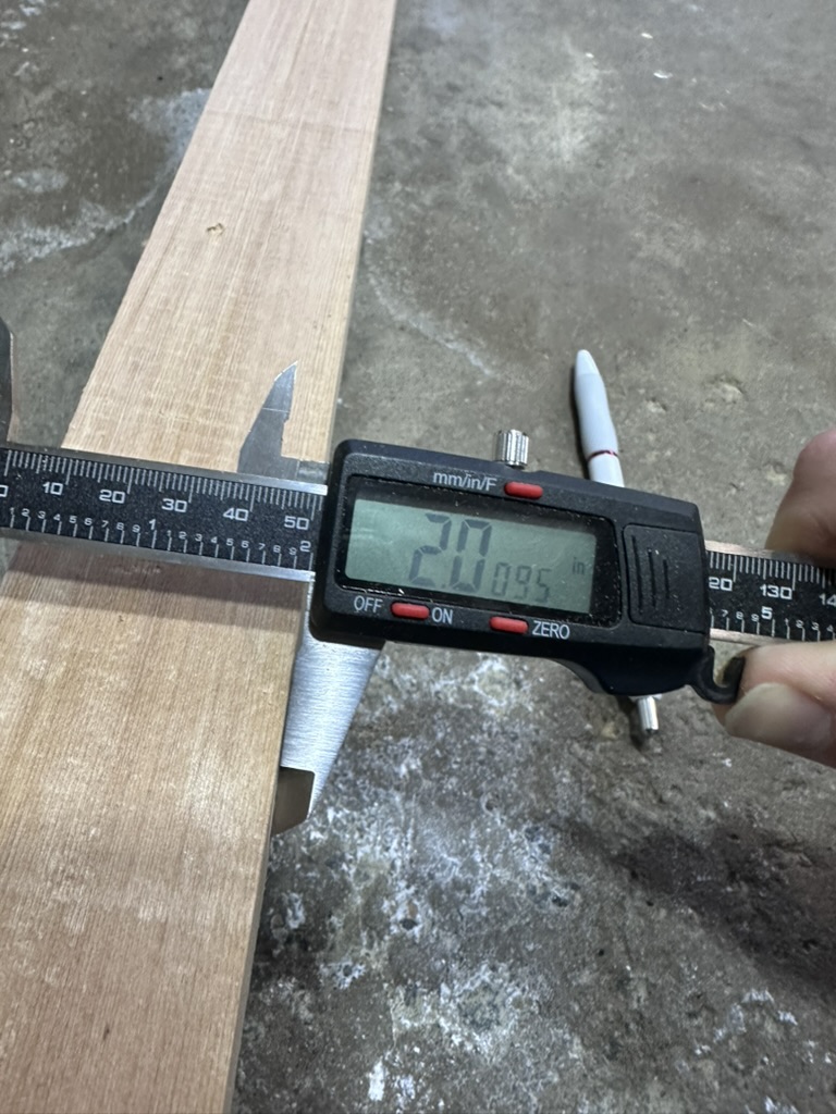
Re-cut side board measuring 2.0095" — almost perfect
I was able to get it almost perfect in size at 2.0095 inches. Then I cut the long strip into the correct length sections using the small miter saw I have at home. I was able to get 4 pieces from that — two more than what I needed, so that's a bonus.
I slid on the 3D printed jig and it fitted perfectly. I pushed the dowels into the gable side of the roof (the holes were already drilled on the CNC), then measured the amount sticking out and put a piece of tape around my drill bit so I'd know the depth I needed to drill to. I used the jig to drill the holes, then took the jig off and drilled to the correct depth using the tape as reference.
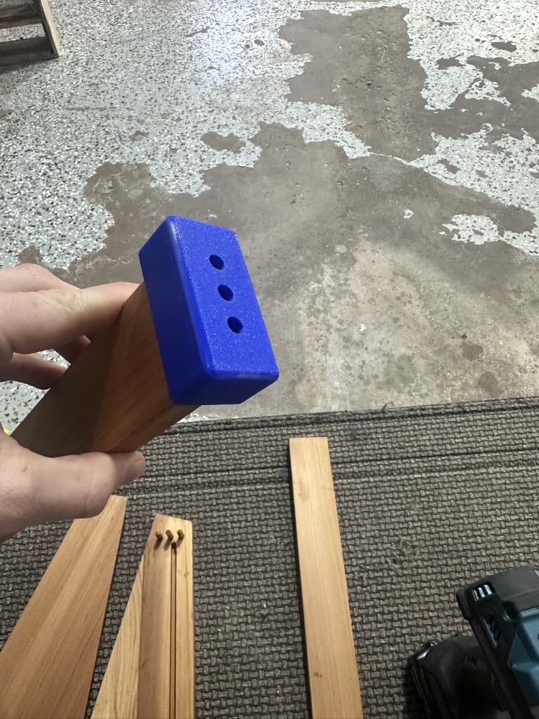
3D printed jig clipped onto the side board for precise hole alignment
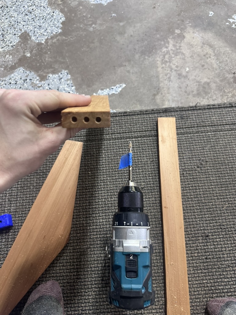
Tape on the drill bit as a depth reference
I test fitted all the parts — a few needed to be drilled out a little more, so I did that until I got a good fit. Then I sanded all the freshly cut sides nicely.
Finishing — Tung Oil
I finished all the parts using tung oil, which is what I use on my cedar bee hives that I don't paint. I like the look of the natural cedar, and it's very weather and rot resistant so it doesn't need paint like pine boxes do. You can still paint cedar if you want, but I prefer the look of the wood.
One important note: you have to use 100% pure tung oil and let it cure for around 30 days if you want to use it for bees. Most "tung oil" isn't really tung oil — anything labeled tung oil at your local hardware store is not likely even tung oil and is not food/bee safe (you need to read the label on the back of the package). I personally use Hope's 100% Pure Tung Oil ($29.99 on Amazon), which I already had on hand.
The best method I found for applying it:
- Apply a generous amount to the wood
- Leave it in the sun for 20 minutes
- Wipe it down
- Let it sit in the sun for around 2–3 hours
I repeated this process 3 times and was happy with the result. Note that you have to wait around 30 days for it to fully cure.
Roof Assembly
After applying the 3 coats of tung oil finish, I bought a piece of ¼" lauan plywood from Lowe's to sit in the groove I made in the gable side of the roof. I cut the ply to the correct dimensions on the table saw, slid it in, and glued up all of the sides.
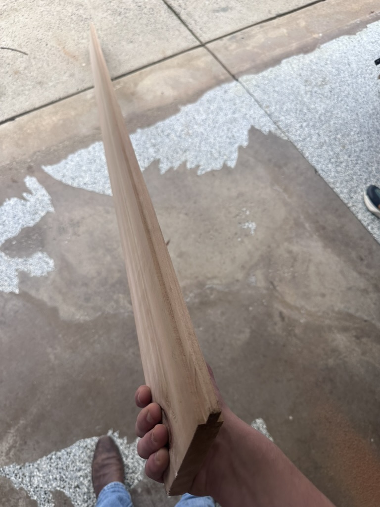
Interior Supports: One thing I should have done was add a groove for the plywood board in the rectangular sides of the roof. Since I hadn't done that, I decided to improvise — I used the previously too-narrow pieces of wood and cut a 15-degree slope on them using the table saw, which was about as close as I could get to match the slope of the roof. I glued them on the inside face and then used the nail gun to put nails from the bottom of the board up into the support. Since these pieces were also not long enough, I used some wedges to get the fit right, then glued up the faces and clamped them together. I used plywood spacers between the clamps and the wood so I wouldn't damage it. This also gives me something I can nail the roof board to and increases the insulation of the beehive since it will be twice as thick in those areas.
Top Support: I also realized I would need to make a top support — something to add strength and also have something to nail the roof board into. The stuff inside the roof doesn't need to look perfect since when I assemble it all it will never be seen. I made the top support from some scrap pine I had laying around. I cut the slope of the roof at the peak, then offset it by the thickness of the roof ridge beams. I used the same pine and cut it in half — most of the cutting for this was done on the miter saw. I glued the supports to the opposing interior faces of the wood, clamped them, and used the nail gun to put nails from the bottom of the board up into the support. Then I nailed the two ridge beams to the angular parts of the support, ensuring they were flush with the CNC-cut slope of the gable sides. This increased the strength of the roof and gives me something to nail the roof board to.
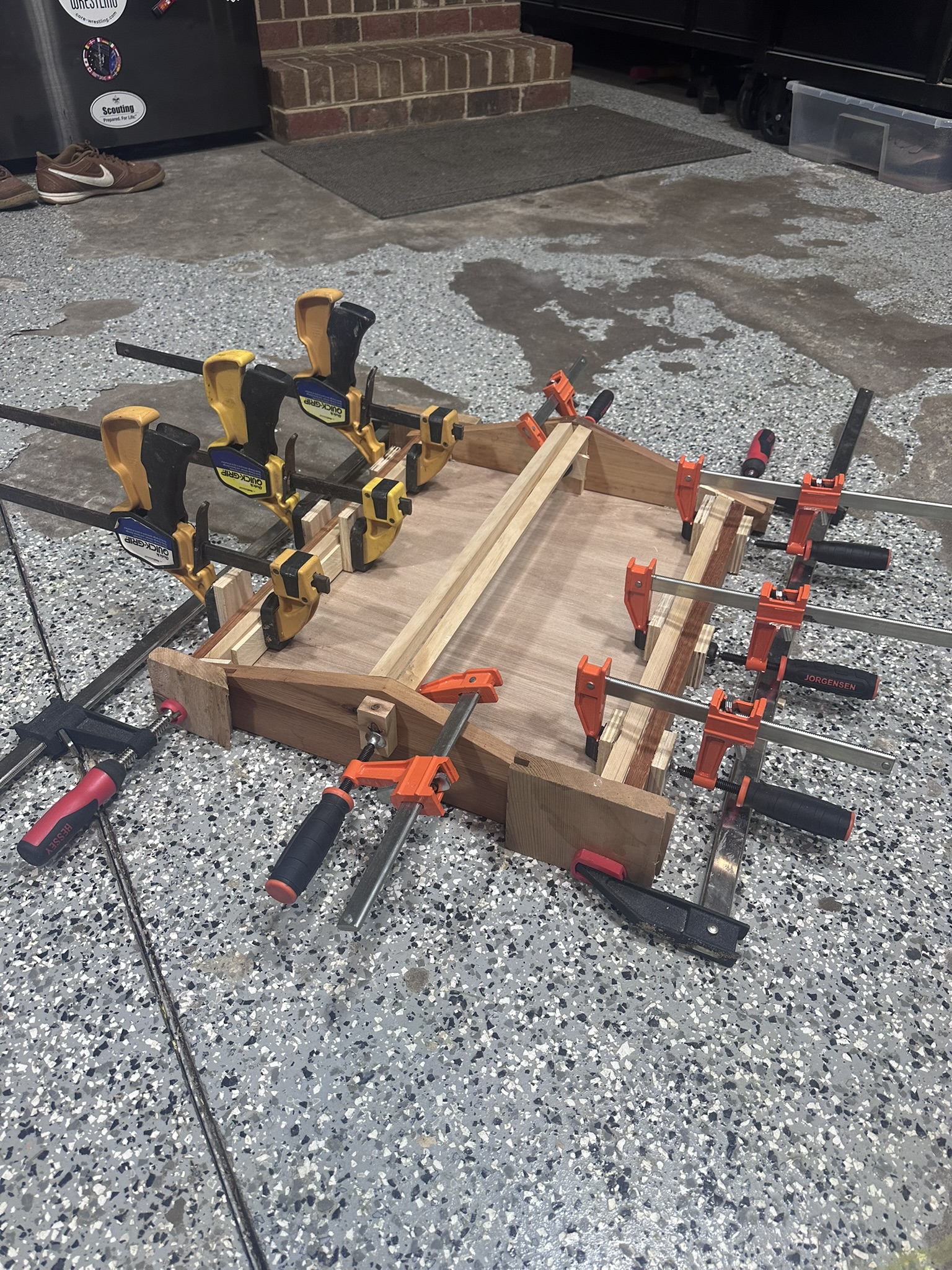
Roof assembly all clamped up with interior supports
After it dried I removed all the clamps and tested the fit on my bee hive box — and it fit perfectly, which I was so happy about.
Roof Board & Copper: After that I got some thicker plywood for the roof, which I hope to wrap with a thin sheet of copper to give it a nice look. The copper will also provide a bit of heat in the winter for the bees, and it looks really cool. More on this will be added in the Final Project — CAD & Build section as I continue the build.
Hive Dimensions
The hive is a 10-frame Langstroth — the most common hive type in the United States. The standard dimensions I'm working with:
- Deep Hive Body: 9⅝" tall × 16¼" wide × 19⅞" long
- Medium Super: 6⅝" tall × 16¼" wide × 19⅞" long