3. Computer controlled cutting
Laser Cutter Safety
Before using the laser cutter, there are safety rules that must be followed. The laser cutter uses a high-powered beam of focused light that can cut, engrave, and burn material — and cause serious injury if used incorrectly. General safety:
- Never leave the laser cutter unattended while it is running
- Always keep the lid closed during operation — the enclosure protects you from the beam and contains fumes
- Know where the emergency stop is before you start
- Never cut materials that produce toxic fumes — PVC, vinyl (unless specifically rated), and certain foams release harmful gases when burned. Always check the material is approved for laser cutting before loading it
- Keep the area around the machine clear
Machine specific: * Always make sure the exhaust and air assist are running before starting a job — without ventilation, fumes build up inside the enclosure * Never leave the machine while it is cutting — watch for flare-ups. Wood and card can catch fire, especially at higher power settings. Have a fire extinguisher accessible * Clean the lens and bed regularly — residue buildup affects cut quality and can become a fire hazard
Parametric Design in Fusion 360
This was my first time using Fusion 360 for a parametric design. My original ambition was a parametric chess board made from interlacing pieces — I ended up with a press-fit box, which was a more realistic first target and still covered all the key concepts.
Understanding Parametric Design
The key idea in parametric design is that you define relationships between dimensions rather than fixed numbers. Change one value — say, the material thickness — and everything that depends on it updates automatically. This is especially powerful for press-fit joinery, where the notch depth must always match the material thickness exactly.
Setting Up Parameters
Before drawing anything, define your parameters. In Fusion 360 go to Modify > Change Parameters and set up the following:
| Parameter | Value | Description |
|---|---|---|
side_X |
150mm | Length of the box |
side_Y |
150mm | Width of the box |
material_thickness |
3mm | Thickness of the sheet material |
kerf |
0.2mm | Laser beam width — affects joint tightness |
corner |
50mm | Corner margin |
notch_width |
(side_X - 2×corner) / 7 | 7 equally spaced notches per side |
notch_depth |
material_thickness | Notch depth always matches material |
Using parameters from the start means you can adjust the box for any material simply by changing material_thickness and kerf — everything else updates accordingly.
[Screenshot of parameter table here]
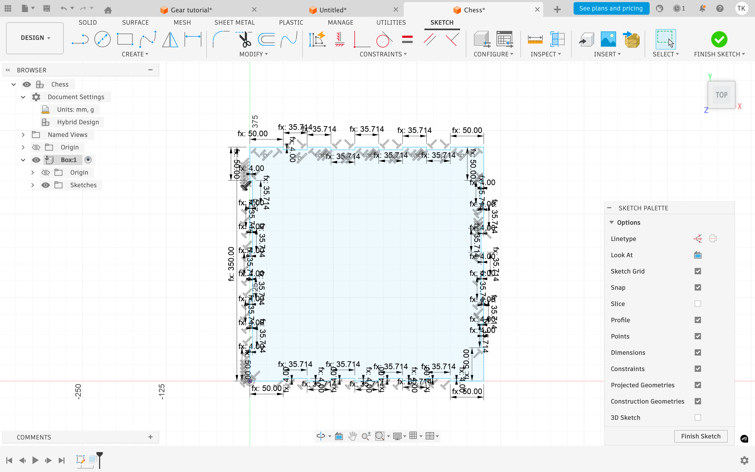
Modeling the Base
Create a new component in Fusion 360 and name it Base. Working in separate components keeps the model organized and prevents sketches from interfering with each other — this was my biggest source of confusion on the first attempt.
Create a new sketch on the XY plane. Draw a square using the Rectangle command. Set the dimensions to side_X by side_Y using your parameters.
Draw the notch profile along one side. Start by marking the corner margins, then divide the remaining length into 7 equal notches using the notch_width parameter. Set the notch depth to notch_depth.
Once one side is complete, mirror it to the opposite side using Sketch > Mirror. Select the geometry and mirror across the centerline — do not copy and paste, as this breaks the parametric relationship. Repeat for the remaining two sides. When the sketch is fully constrained — all lines black, no blue remaining — exit the sketch.
Use Extrude to give the base thickness. Set the depth to material_thickness.
Modeling the Walls
Each wall is a separate component. Keep them separate so they can be laid flat later for the laser cutting file.
Left wall:
Create a new component named Wall Left. Create a sketch on the left edge face of the extruded base. Use the Project tool (P) to project the edges and points of the base into the current sketch. This ensures the wall dimensions are driven by the base geometry — change the base and the wall updates too. Draw the wall profile, including the corresponding notches that interlock with the base.
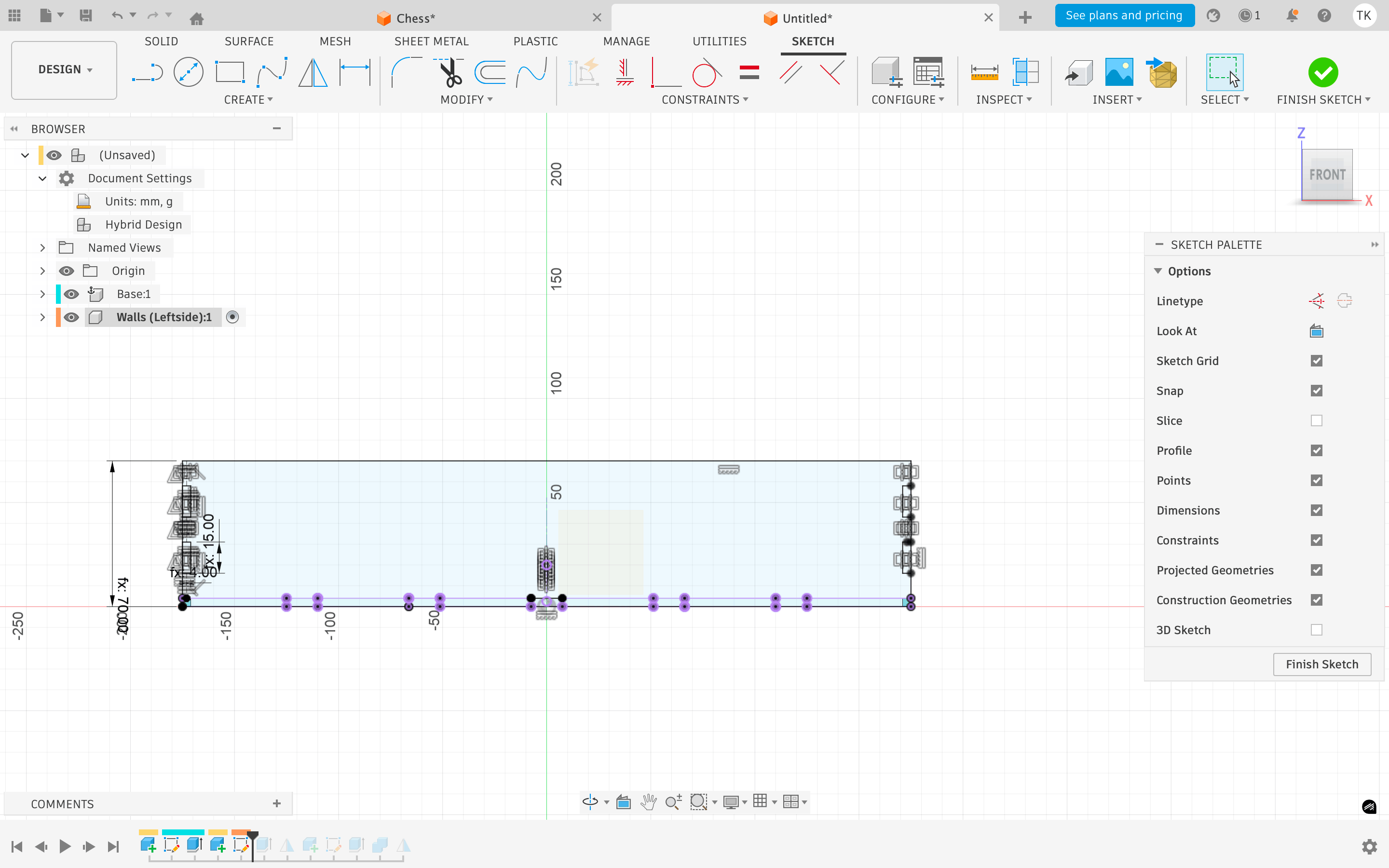
Extrude by material_thickness.
Right wall:
Rather than redrawing, go to the main component level. Use Mirror > Mirror Component and select the left wall. Set the mirror plane to the YZ plane (the central vertical plane). This is the advantage of building everything centered on the 0,0,0 origin — mirroring is clean and predictable.
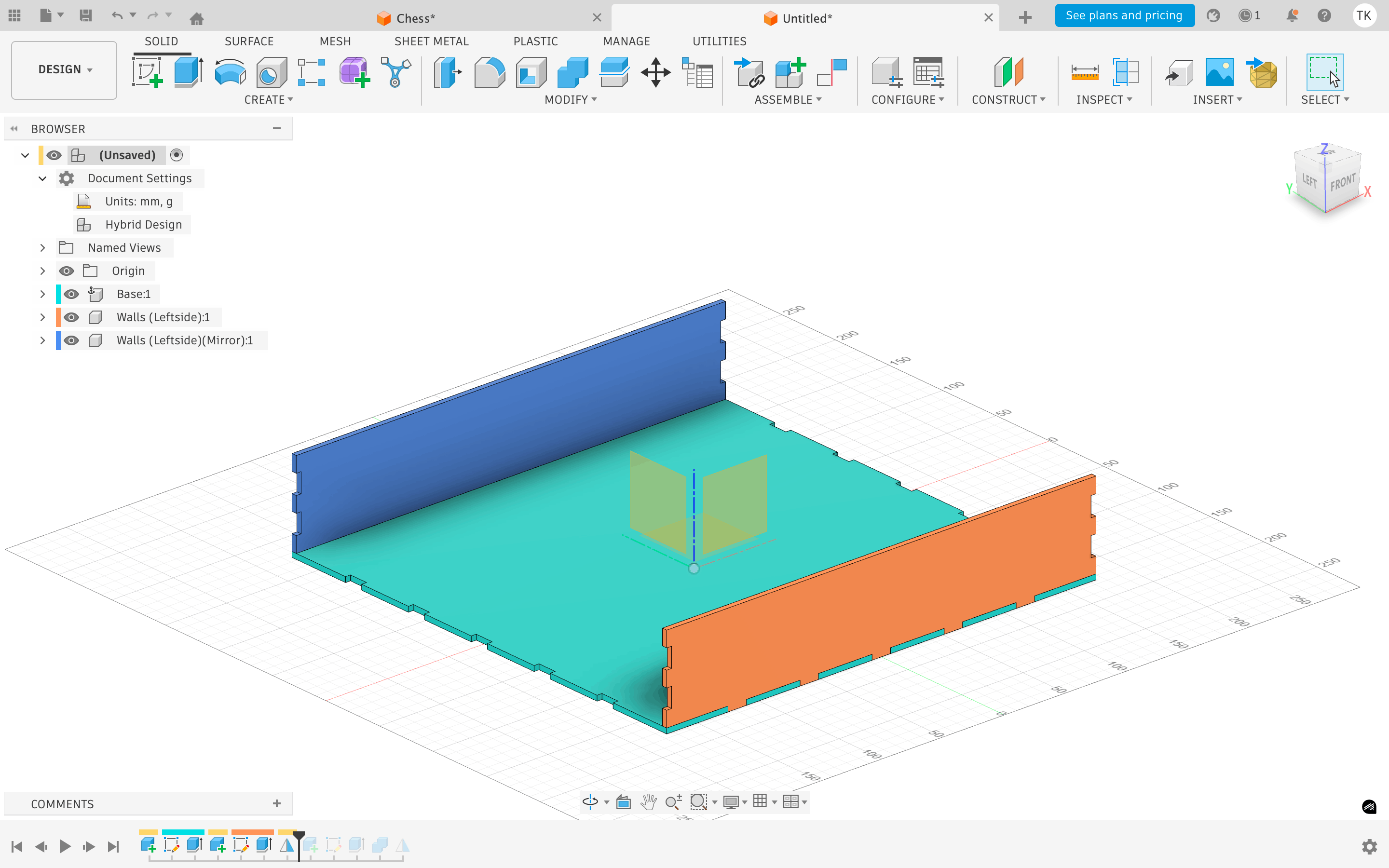
Front and back walls:
Create a new component named Wall Front. Use the Project tool to pull in reference geometry from the existing walls and base. Draw the wall rectangle and extrude. Where the front wall overlaps the side walls, use Modify > Combine > Cut to subtract the side wall volumes from the front wall — this creates the correct interlocking notch automatically. Mirror the front wall across the XZ plane to create the back wall.
Preparing the File for Laser Cutting
Once all components are complete, copy the entire assembly.
In the copy, rotate and move each component flat onto the XY plane — this simulates how the pieces will be laid on the sheet material.
For each component, create a new sketch on the top face and use Project to project the outline into the sketch.
Right-click the sketch folder and export as DXF — this is the file format the laser cutter software expects.
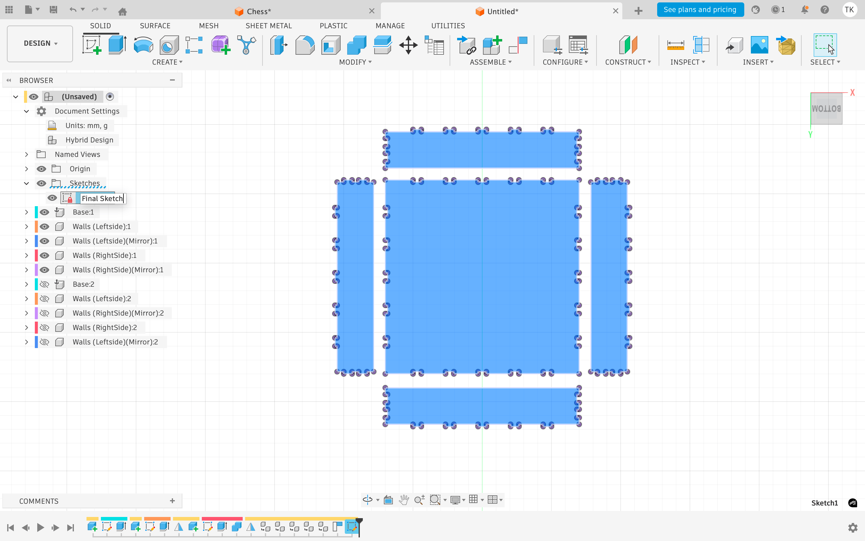
Open the DXF in your laser cutter software, check that all lines are clean and closed, set your power and speed settings for the material, and run the job.
How the Press-Fit Works The box holds together without glue or fasteners. The notches cut into each piece are sized to material_thickness minus the kerf — so when two pieces slot together, the laser’s cut width creates a friction fit that holds the joint firmly. If the fit is too tight or too loose, adjust the kerf parameter and re-export. This is the whole point of the parametric approach — dialing in the fit takes seconds, not a full redraw.
/WhatsApp Image 2026-06-17 at 19.58.01 (1).jpeg)
Using the Vinyl Cutter
For this exercise I used the vinyl cutter to produce a rotary capacitive touch pad cut from copper tape. The pad consists of six crescent-shaped segments arranged in a ring, with a small gap between each one. The idea is that as a finger moves around the ring, it overlaps with a gradually changing combination of segments — each segment contributing a slightly different capacitance reading depending on how much of it is covered.
The science of rotary capacitive sensing:
A single touch pad can only tell you whether a finger is present or not. A rotary pad works differently — by arranging multiple pads in a circle with overlapping coverage zones, the microcontroller can read the relative capacitance across all segments simultaneously and calculate the angular position of the finger. As the finger moves clockwise, one segment’s reading rises while the adjacent one falls. The ratio between those readings is what encodes the position.
Design Process
Rhino and DXF Export
I designed the six crescent segments in Rhino, arranging them at equal 60° intervals around a central point with a consistent gap between each one. The gap is important — if the segments touch each other they short circuit and the sensing fails entirely. Once the geometry was clean and all curves were closed, I exported the file as a DXF — the format Silhouette Studio requires for importing vector geometry.
/WhatsApp Image 2026-05-30 at 18.49.15 (4).jpeg)
Setting Up Silhouette Studio
-
Step 1 — Import the DXF Open Silhouette Studio and import the DXF file. Check that all paths have imported correctly — open paths or missing segments will result in incomplete cuts. Scale and position the design on the virtual cutting mat, leaving a margin from the edges.
-
Step 2 — Set the material Silhouette Studio does not have a preset for copper tape. The closest equivalent in terms of thickness and backing is aluminium foil tape — I selected this as the material to get a starting point for the automatic cut settings.
-
Step 3 — Calibrate speed and pressure This is the most critical step. The goal is to cut cleanly through the copper layer without cutting through the backing paper beneath it. Too much pressure and the blade goes through everything — the pad lifts off with the carrier sheet destroyed. Too little and the copper doesn’t cut fully, leaving tabs that tear rather than separate cleanly. I ran several test cuts on offcuts of copper tape, adjusting speed and pressure in small increments each time until the cut was clean and the backing paper remained intact. Record the settings that work before sending the final job — it is easy to lose track between tests.
-
Step 4 — Feed the copper tape Feed the copper tape carefully onto the cutting mat, pressing it down evenly to avoid bubbles or lifting at the edges. A pad that shifts mid-cut will misalign the segments and ruin the geometry.
-
Step 5 — Send the cut Once everything is set, send the job to the cutter. Watch the first few passes to make sure the blade is tracking correctly and the material is not lifting.
/WhatsApp Image 2026-05-30 at 18.49.16.jpeg)
/WhatsApp Image 2026-05-30 at 18.49.16 (2).jpeg)
I soldered some wires with pin-heads that connect my rotary pad to the micro-controler which I will later test to move a stepper!
Group Assignment for this week is here
Link Not yet up… waiting on the upload!