2. Computer Aided design
Testing 3D Software
Rhino — 3D Modeling & Grasshopper
I have significant prior experience with Rhino, but I wanted to work smarter — specifically by exploring parametric modeling through Grasshopper, which I had never used before. Rhino confirmed itself as my preferred space for geometric thinking. Compared to Fusion 360, it feels more fluid for pure form exploration. Fusion, I decided, is better suited to a later stage of the design process — when materiality, components, and motion need to be resolved.
Pure Geometry — The Dodecahedron
I think of geometry as a language. My method follows traditions like the arabesque, where the artist engages in a process of discovery. Take a pentagon: connect all its vertices and a smaller pentagon emerges at the center — repeating toward infinity in a process of self-similar, fractal growth. My interest is to apply this logic in three dimensions.
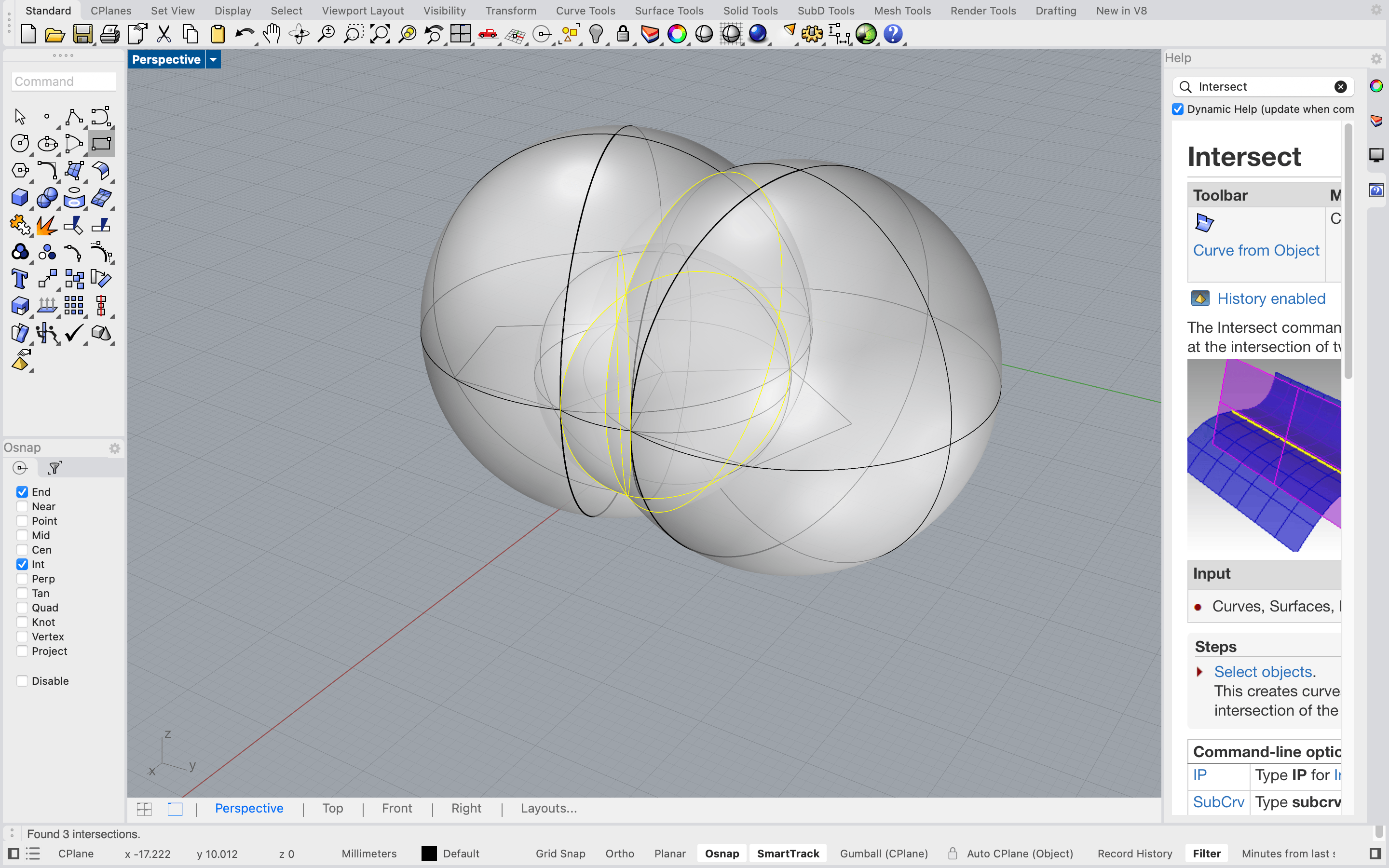
I chose the dodecahedron — one of the five Platonic solids, composed of 12 identical pentagonal faces forming a closed volume. Here is the sequence I followed to build it in Rhino: Draw a pentagon on the default XY plane using the Polygon command, setting the number of sides to 5. Find the dihedral angle — the 3D angle between two pentagonal faces. I did this geometrically by placing three spheres whose intersection point gave me the correct angle. The Sphere command was used here, and the intersection found with Intersect.
Rotate the pentagon into 3D — this is where CPlane became essential. By redefining the construction plane to align with the face of the pentagon, I could rotate and place the next face relative to it, rather than working in the fixed world XY. The 3DRotate command was then used to tip the adjacent pentagon to the correct dihedral angle.
Array around the axis — once one face-to-face relationship was correct, I used ArrayPolar to repeat the pentagon around a central axis, building up the cap of the dodecahedron. Mirror and close — the bottom half was generated by mirroring, and the form was closed into a complete solid. Throughout this process, layers were essential for staying organized. Each stage of construction — the scaffolding spheres, the reference geometry, the final faces — lived on its own layer, making it easy to toggle visibility and keep the viewport readable.
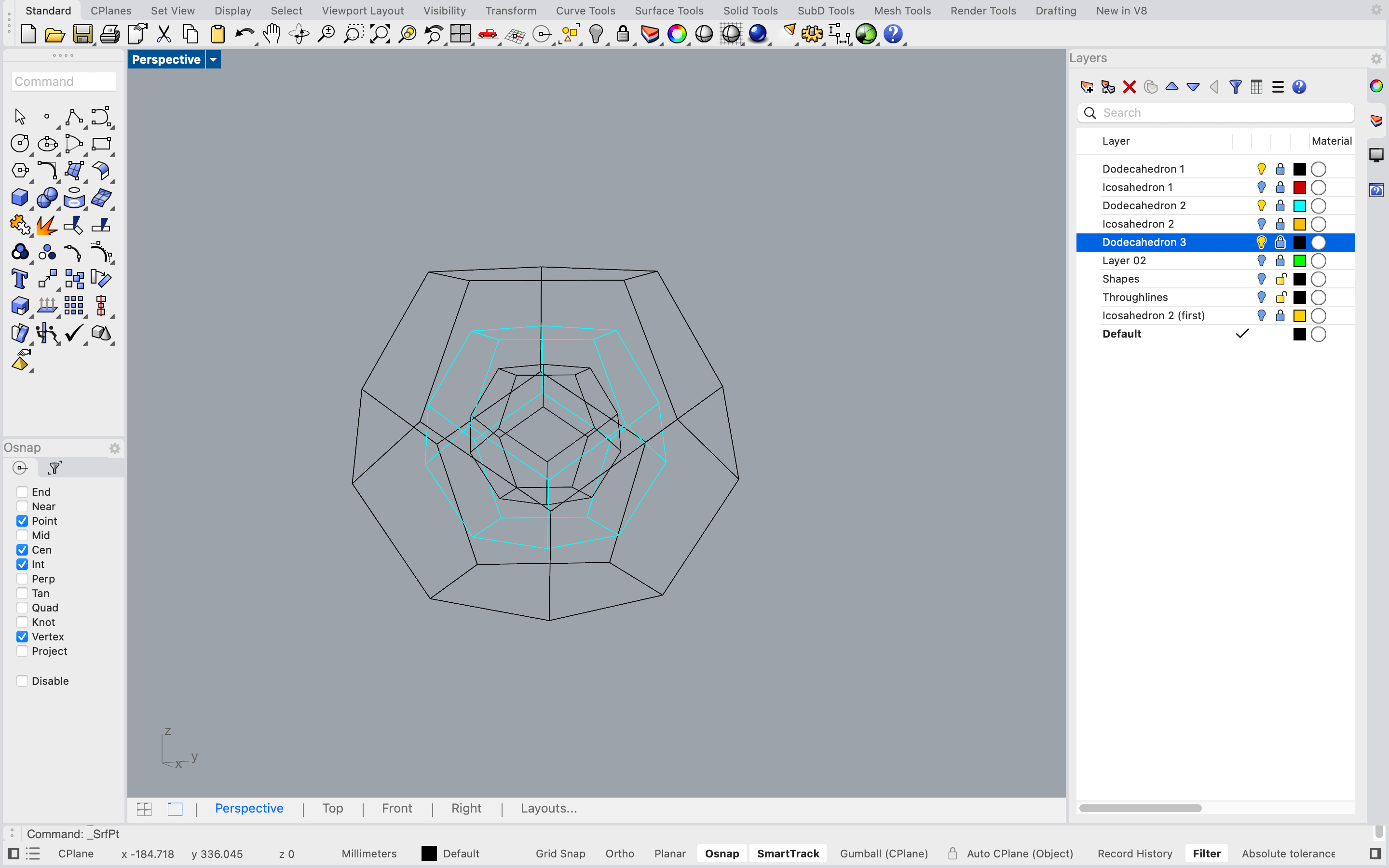
With the dodecahedron built, I began investigating its geometric relationships — the 3D equivalent of the fractal patterns found in the 2D pentagon. This led me to the concept of dual geometries: the dual of the dodecahedron is the icosahedron, where each face of one corresponds to a vertex of the other.
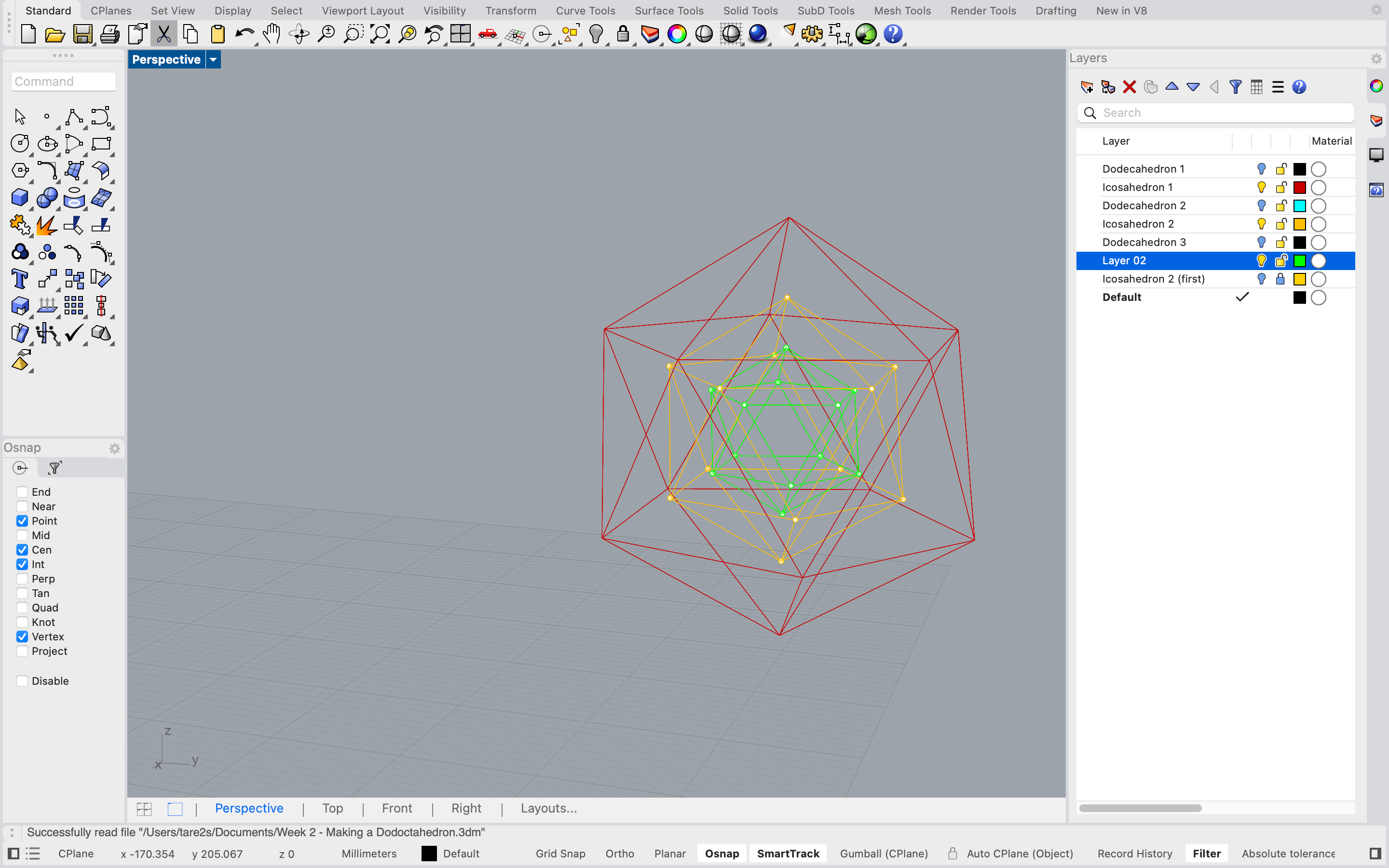
I then organized the model into layers by dimension and began playing with derived forms using the dodecahedron as a scaffold.
Grasshopper — Parametric Modeling
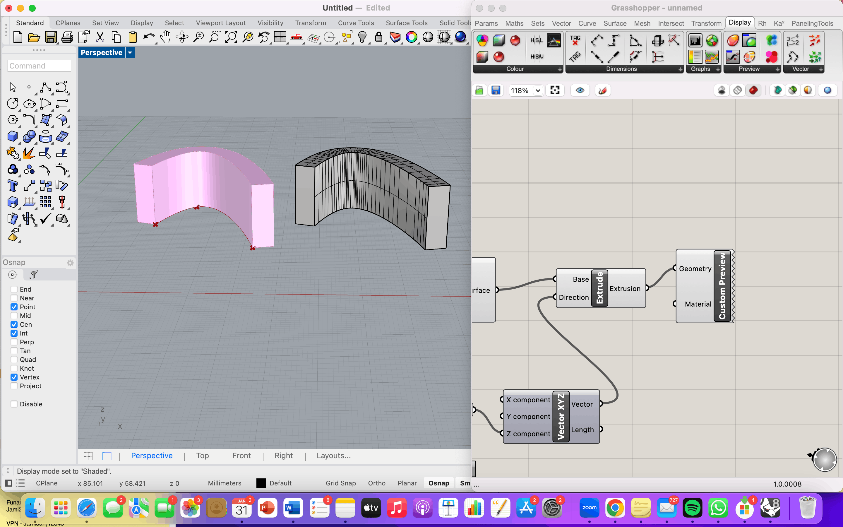
Grasshopper was entirely new territory. I started simple — modeling an extruded curve parametrically and learning how to bake geometry back into Rhino. This immediately struck me as powerful for design iteration: tweak the Grasshopper definition, regenerate new forms instantly.
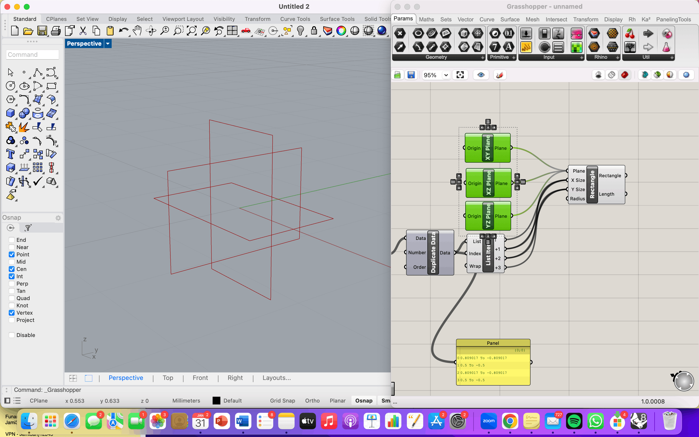
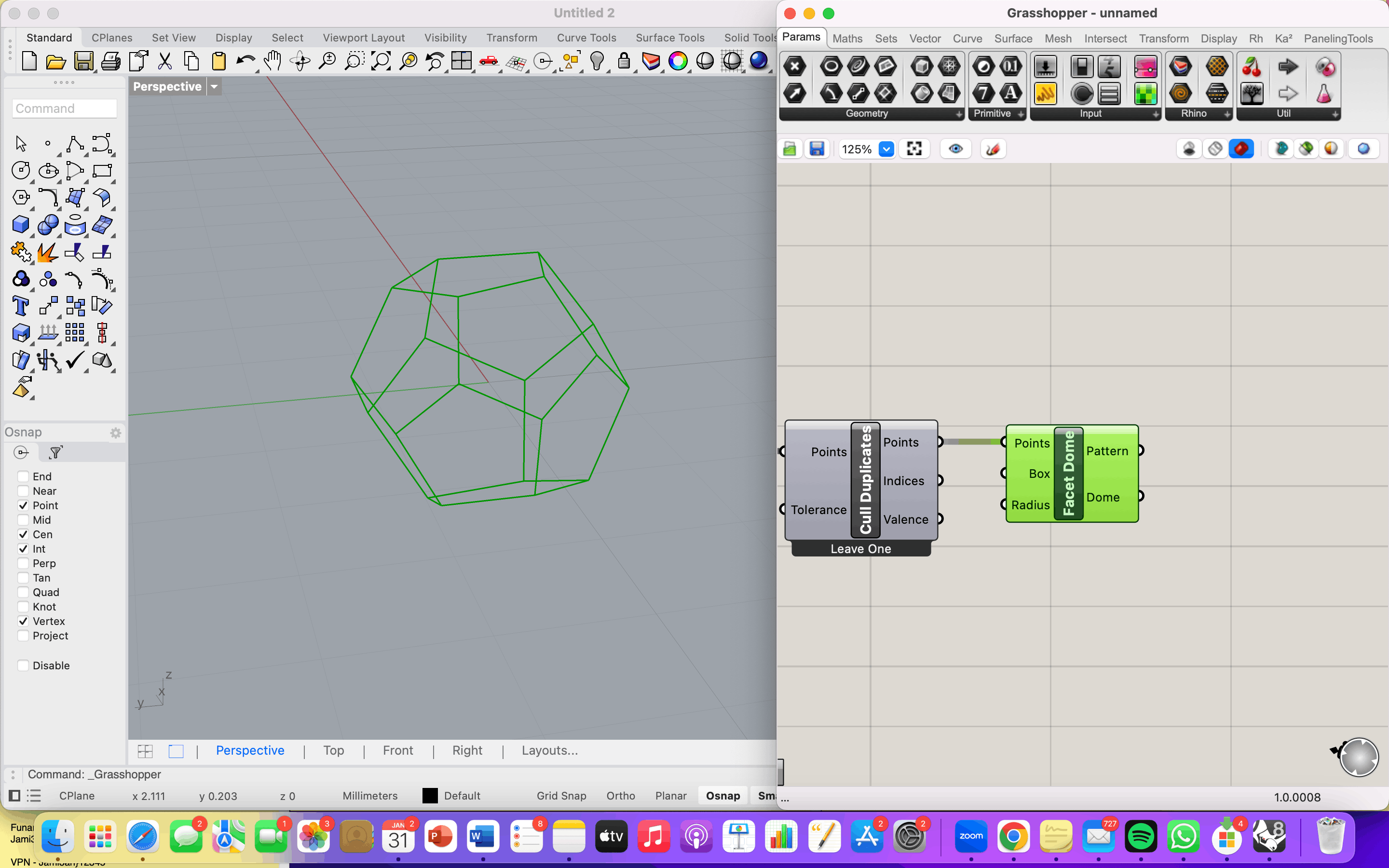
I then followed a tutorial to model the dodecahedron parametrically (reference: https://www.youtube.com/watch?v=XQTDyWj1ITE). The main logic of the definition works as follows:
Define the vertices mathematically — the 20 vertices of a dodecahedron can be expressed using the golden ratio (φ). A Number slider sets the scale, and Point components place each vertex in 3D space using these coordinates.
Connect the faces — a PolyLine component connects the correct vertices in the right sequence to form each pentagonal face. Orient and array — rather than rotating manually, transformations are handled mathematically using Rotate and Orient components that reference vectors and planes. Bake — once the definition produces the correct geometry, the Bake function transfers it into the Rhino viewport as live geometry.
What became clear is that building a parametric model is itself a creative act: the same form can be expressed mathematically in multiple ways, and choosing how to express it is a design decision. I’m still learning, but the plan is to start with simpler forms and build up from there.
Fusion 360 — Mechanical Components
Rhino vs. Fusion — Two Different Logics Before getting into the work, it’s worth reflecting on the fundamental difference between these two tools, because understanding that difference helped me understand how to use each one better.
Rhino is a surface and curve modeler. You work freely — drawing lines, curves, and surfaces in space, assembling geometry as you go. There is no enforced structure. This freedom makes it ideal for geometric exploration and form-finding, but it also means organization is entirely up to you.
Fusion 360 is a parametric, feature-based modeler built around components and a timeline. Every operation — a sketch, an extrusion, a fillet — is recorded as a step in the timeline and can be edited or rolled back at any point. Components are discrete parts that can be assembled, jointed, and set into motion relative to each other. This structure makes Fusion more rigid to learn, but extremely powerful once a design needs to be engineered rather than just imagined. In short: Rhino for thinking, Fusion for making.
Modeling a Gear and Slider Mechanism
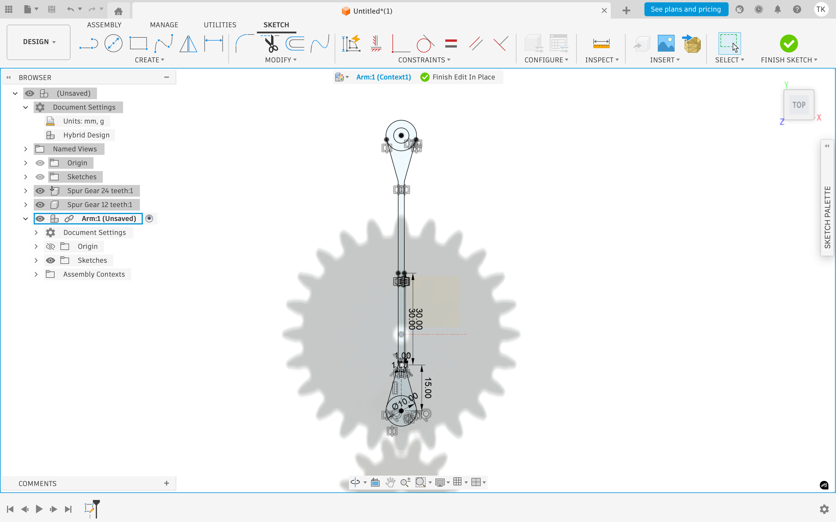
Given my interest in kinetic design, I chose to follow a tutorial on a gear and slider mechanism — a system that converts rotary motion into linear motion. The key steps were:
-
Generate the gear — Fusion has a built-in Gear Generator (found under Design > Add-ins > Gear). Rather than drawing a gear tooth-by-tooth, I input the parameters — number of teeth, module, pressure angle — and the tool generated the geometry automatically. This was a good introduction to how Fusion rewards precision: you design by defining constraints, not by drawing.
-
Build the slider — the slider was sketched in Sketch Mode and extruded into a 3D component. I appreciated that sketch mode lets you return and edit the base sketch at any point — the 3D geometry updates automatically.
-
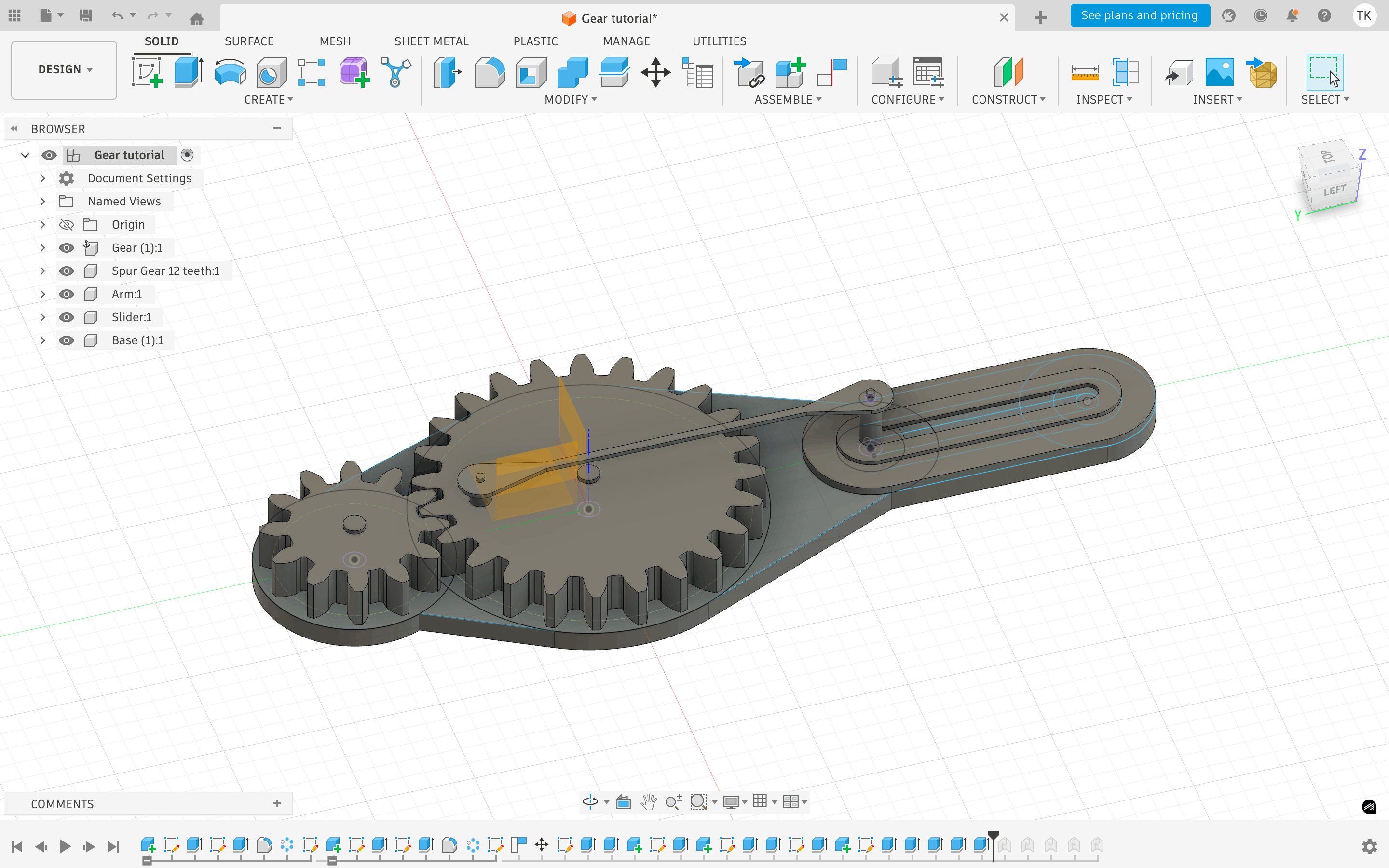
Assemble and joint — each part was defined as its own Component, then connected using Joints. A Revolute Joint was applied to the gear (rotation) and a Slider Joint to the rack (linear motion). Fusion then enforces these relationships physically.
-
Simulate motion — once the joints were defined, I could drag the gear in the viewport and watch the slider respond in real time. This kind of immediate feedback is something Rhino simply cannot do.
I followed the tutorial twice — the first time I got confused by the component hierarchy, which is not intuitive at first. The second run made the logic click. The timeline was key: being able to see every operation in sequence, and roll back to fix a mistake without starting over, is a genuinely different way of working.
2D Software — Inkscape & Photopea
Raster vs. Vector
Before getting into the software, it’s worth understanding the difference between two types of digital images.
A raster image is made of pixels. Zoom in far enough and it breaks into dots. Photos and screenshots are raster. A vector image is made of mathematical paths — lines and curves that can scale infinitely without losing quality. The distinction matters in fabrication because different processes require different file types.
Inkscape
Inkscape is a free, open-source vector editor — essentially a free version of Illustrator. It works natively in SVG but can also import and export raster formats like PNG, which makes it a useful bridge between the two worlds.
I evaluated the main tools and found it capable for 2D work. The ones I used most were the Selection tool for moving and scaling objects, the Node tool for editing paths at the point level, the Fill and Stroke panel for controlling color and line weight, and the Layers panel for staying organized — same logic as Rhino layers. The Export panel lets you output a PNG at a defined DPI, which is important when preparing files for fabrication.
The limitations are real though. The interface feels dated, it gets slow with complex files, and it lacks the precision of a proper CAD tool — no parametric constraints, snapping is fiddly. For geometric work it can feel clumsy. But for preparing and editing 2D files it does the job.
Coloring a PCB Board Image
I used Inkscape to prepare a colored raster image of my PCB board before sending it into production. The board came in as a black and white trace file — black background, white traces and pads.
The process was simple. I imported the image, then drew a rectangle over the board area and filled it with color using the Fill and Stroke panel — placing it as a layer beneath the traces. I then adjusted the blend mode of the trace layer so the black background dropped out and only the white traces remained visible over the color. Once it looked right, I exported it as a PNG at the correct DPI for the production workflow.
Making a pentagone fractile
- I simply used the polygone start tool, pressed the pentagone shape and adjust the fill and stroke, so that its just a boundary.
/Screenshot 2026-06-28 at 8.40.22 PM.png)
- To make a fractile pattern I need to connect the points. For that you need to enable the snap. Go to the advanced settings and make sure the snap is enabled for endpoints and interesctions of lines/ pathways.
/Screenshot 2026-06-28 at 8.42.31 PM.png)
- Finally I used the bucket/paint tool to color the patten…
/Screenshot 2026-06-28 at 8.52.22 PM.png)
Photopea
Photopea’s basically a free Photoshop that runs right in your browser — no install, no account needed.Photopea’s basically a free Photoshop that runs right in your browser — no install, no account needed. I use it for raster, pixel-based editing, so things like photos and image touch-ups rather than clean vector shapes. It even opens .psd and .ai files, which is handy if I’m working with something made in actual Photoshop or Illustrator. For my purposes it’s been the easiest free option for anything image-based.
Image raster edits
Since I don’t have photoshop, I wanted to test photopea - it will be helpful down the line. I simply wanted to edit my personal headshot. To make the background black and white.
- Open new file using the basic settings was fine for now.
/Photopea /Screenshot 2026-06-30 at 11.42.49 AM.png)
-
Then I when to file/open to open the image I wanted to work on. The image will automatically go into the background. If you ‘open & place’ you will place the image on a seporate layer.
-
After this I used the subject tool under select to outline my self. It worked really well.
/Photopea /Screenshot 2026-06-30 at 11.51.16 AM.png)
- Then I simple went select inverse to select the background. Then went to Image/ adjustment/ white & black
/Photopea /Screenshot 2026-03-30 at 10.41.38 PM.png)
Reflection
The two program are worlds part, each specific for a certain function. For machine oporation best go with the vector software, for more image based jepg. png. best go with the raster.
File Compression
To keep file sizes manageable for documentation and upload, I compressed all images and videos before publishing.
Image Compression — PDF Guru
For images, I used PDF Guru (pdfguru.com), an online compression tool that supports JPG, PNG, and other formats. The process is straightforward:
-
Export screenshots and renders from Rhino/Fusion as PNG files
-
Drag and drop the files into the PDF Guru upload area (accepts up to 350MB)
-
The tool automatically reduces file size while preserving visual quality
-
Download the compressed files and replace the originals
Video Compression — YouTube
For video, I used YouTube’s built-in compression engine by uploading screen recordings directly as unlisted videos. YouTube automatically re-encodes uploaded footage — reducing file size significantly — while keeping the video streamable and embeddable in documentation. The process: Export the screen recording (e.g. from QuickTime) Upload to YouTube, set visibility to Unlisted Once processed, embed the YouTube link in the documentation This avoids having to host heavy video files directly and ensures smooth playback anywhere.
Whats App
Turns out whats app have a very good compression engine. This was honestly the most useful method during the program. Simply send image and videos to your self and they automatically get compressed!