Archive
Geometry Study — The Hidden Geometry of Flowers
Background
I chose the geometry of this sculpture almost arbitrarily — or so it seemed at the time. The seed was planted in 2020, during a previous project in which I used the dodecahedron not as a visible form but as an invisible scaffolding. The piece was a fire pit and permanent installation. I built a gradient that circled the geometry — as you moved around it, the density of the structure shifted, allowing more or less light and flame to pass through. The dodecahedron was never seen, but everything in the piece was organised by it.

That experience opened a door. Through a subsequent study of Islamic art and the arabesque tradition, I became increasingly interested in the mathematics embedded in geometric form as a living language. What fascinated me was the way these mathematical relationships appear across scales and across disciplines: in the molecular lattice of a crystal, in the spiral of a blooming flower, in the branching logic of a tree, in the orbital paths of planets. The same ratios, the same proportions, appearing everywhere. This led me to the work of Keith Critchlow and others who have studied the philosophy of geometry — how numbers, patterns and rhythms were understood in ancient traditions not merely as tools of measurement but as a universal language, a way of reading the deep structure of the world. I became interested in geometric reasoning as a design methodology: beginning not with a shape in mind but with a principle, and allowing the form to emerge through discovery.
First Sketch — Into Three Dimensions
From the beginning I wanted to take what I had learned through the arabesque and push it into three dimensions — and then further, into the fourth dimension of movement. In the arabesque tradition, the pentagon holds a particular fascination. Connect all the vertices of a pentagon and a smaller pentagon emerges at the center. Connect those vertices and another emerges inside that. This process continues infinitely — each iteration self-similar, each one generated by the one before. It is fractal growth through pure geometric logic. This principle has a direct equivalent in three dimensions. The dodecahedron — a solid made of twelve identical pentagonal faces — has what is known as a dual pair: the icosahedron, a solid made of twenty triangular faces. The relationship between them is precise and reciprocal: if you take a dodecahedron and place a point at the center of each of its twelve faces, then connect those points, you get an icosahedron. Perform the same operation on the icosahedron — a point at the center of each of its twenty faces — and you recover a dodecahedron. They generate each other. They are two expressions of the same underlying geometry, nested inside one another, each one implicit in the other’s structure.
/Rhino/Screen Shot 2026-01-31 at 11.51.58 AM.png)
From this principle I decided to work with two dodecahedrons produced through exactly this process: a dodecahedron, its dual icosahedron inscribed within it, and a second smaller dodecahedron inscribed within that — three nested geometries, each one born from the faces of the one surrounding it, sharing a common center. The immediate design idea was to set both dodecahedrons in rotation — but along different axes, and at different speeds. Crucially, the axes themselves are not arbitrary: they are defined by the geometry of the dodecahedron itself, running through opposite vertices of the form. This brought the central design challenge into focus:
How can two nested dodecahedrons sharing a common center be rotated simultaneously along different axes and at different speeds?
Everything that followed was an attempt to answer that question.
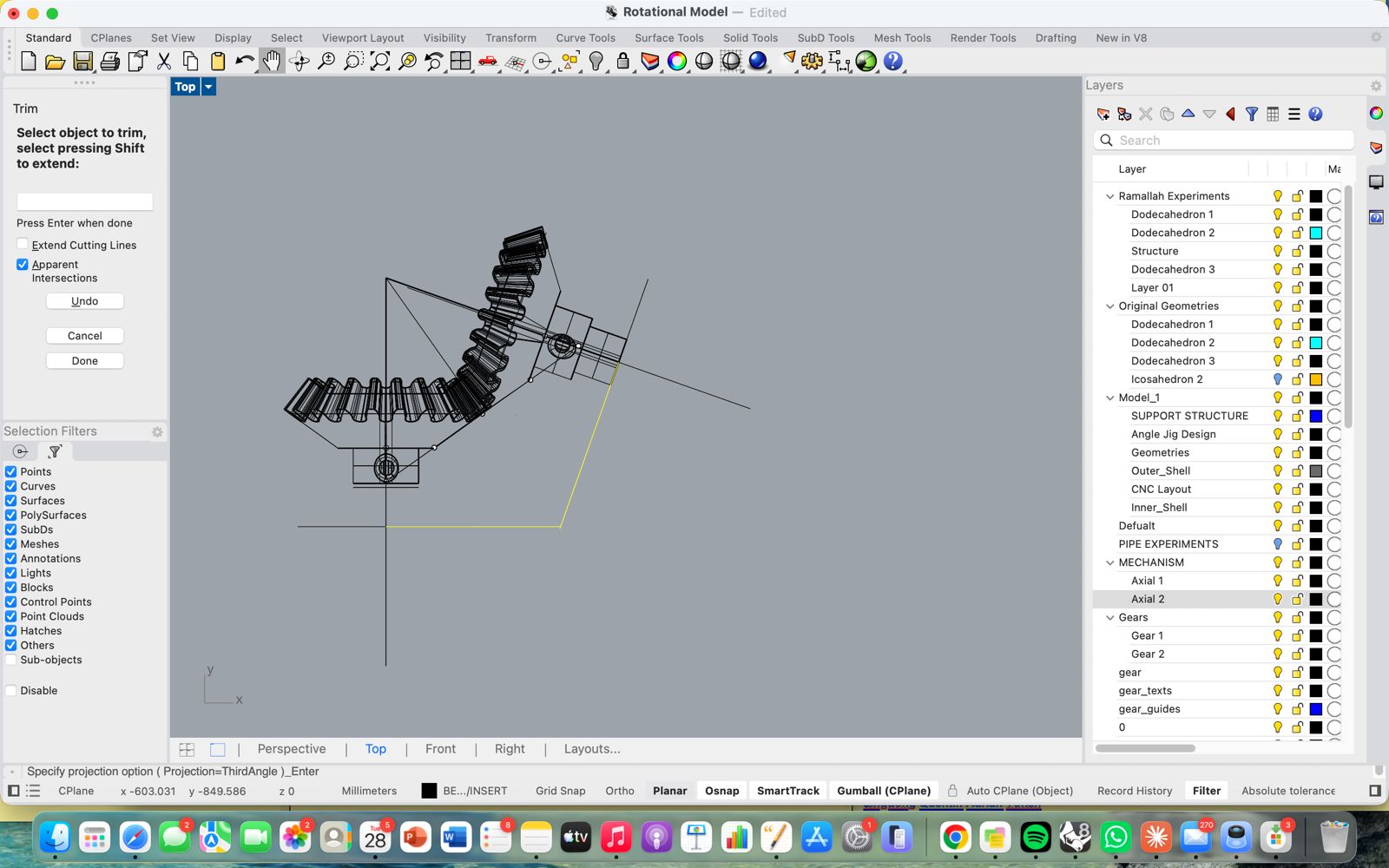
Geometry Study & Simulation — Animating the Motion in Grasshopper
Before thinking about physical constraints, motors, or mechanics, I wanted to see the motion. To understand whether the concept was visually compelling — whether two nested dodecahedrons rotating on different axes at different speeds produced something dynamic and interesting — I needed to observe it in real time. Grasshopper was the right tool for this: it allowed me to animate the pure geometry in digital space, completely unconstrained by the physical world.
Building the Rotation Model
-
Step 1 — Reference the geometry Bring both dodecahedron geometries into Grasshopper by adding two Curve components to the canvas and setting each one to the corresponding geometry in the Rhino model using Set Multiple Curves. Add a Point component and set it to the shared center point of both geometries in Rhino — this becomes the pivot for all rotations.
-
Step 2 — Define the rotation axes Add a Rotate 3D component for each geometry. Each one needs a vector input defining its axis of rotation. For the initial test I used the built-in Unit X and Unit Y vectors — one geometry rotating around the X axis, the other around Y. In the more refined model I defined custom axes using a 2 Point Vector component, allowing me to align the rotation axes precisely with the geometry of the dodecahedron itself — running through opposite vertices as the form dictates.
- Step 3 — Add manual rotation control Connect two Number Slider components, each set to a range of 0–360 degrees, one for each geometry. This allowed me to manually rotate each dodecahedron independently and observe the relationship between them at any given angle. Use a Merge component to combine the outputs where needed.
/Rhino/grasshopper /Screen Shot 2026-01-31 at 1.33.16 PM.png)
Adding Timeline — Simultaneous Auto-Rotation
The manual slider model had a limitation: I could only rotate one geometry at a time, which made it impossible to observe the two forms moving together. To animate both simultaneously and let them run continuously I used the Timeline plugin.
-
Step 1 — Install Timeline Download and install Timeline from Food4Rhino and add it to the Grasshopper canvas.
-
Step 2 — Map time to rotation angle Add two Construct Domain components — one for each geometry — defining the angular range each one will sweep through. Connect each output to a Remap Numbers component, using the Timeline’s time output as the input value and the constructed domain as the target range. The remapped output feeds directly into the angle input of each Rotate 3D component.
-
Step 3 — Set different speeds By adjusting the domain ranges relative to each other, the two geometries rotate at different speeds — one completing a full revolution faster than the other. This misalignment of rhythm is what produces the visual interest: the relationship between the two forms is constantly shifting, never repeating exactly. Scrub the Timeline slider to watch both geometries rotate together in real time.
What the Simulation Revealed
Seeing the two geometries rotate together for the first time confirmed the concept was worth pursuing. The motion had the quality I was looking for — not mechanical or repetitive, but alive. The two forms drift in and out of alignment, casting different shadow relationships, opening and closing the space between them. The misalignment of their rhythms is precisely what gives the piece its tension.
It also immediately raised the central mechanical question: how do you physically rotate two concentric geometries around different axes, driven by independent motors, while keeping them structurally connected at a shared center? Now it was time to think about this challegne with the constraints of the physical world…
Prototyping & Mechanism Design — Thinking Through the Mechanics
Before getting into the details of the current design, it’s worth being clear about what the mechanical problem actually is — because the constraints it imposes shaped every decision that followed.
The concept calls for two nested dodecahedrons rotating simultaneously around different axes. If both geometries shared the same axis of rotation the problem would be relatively straightforward — a single shaft, two concentric mounts, two motors. But they don’t. The axes are offset from each other, defined by the geometry of the dodecahedron itself.
This creates a collision problem. As soon as two geometries rotate around axes that are not parallel, their paths through space will eventually intersect. The outer geometry risks hitting the inner one, or both risk hitting the shaft and drive system connecting them to the motors. The rotational envelopes of the two forms overlap. The central question is therefore: how do you achieve two simultaneous, independent rotations around non-parallel axes, within a shared structure, without the geometries interfering with each other or with their own drive system?
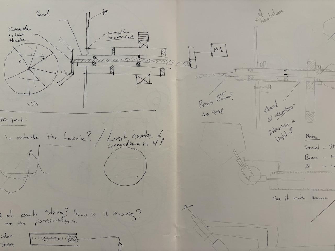
The first insight came through sketching. Looking at the dodecahedron, I realised that the two faces perpendicular to each axis of rotation are natural entry points — doorways through which to access the center of the structure without interfering with the rotation itself. I sketched out a number of ideas along this logic. Most of them involved two separate drive systems, one on each side of the structure — one motor rotating the outer geometry, another rotating the inner. It worked in principle but felt inelegant. Two drivers on opposite ends of the structure meant a bulkier, more symmetrical setup that worked against the visual simplicity I was after.
After some thinking — and a useful conversation with Dani — a cleaner solution emerged: three concentric shafts and a bevel gear. One shaft carries the outer geometry, a second shaft inside it carries the inner geometry, and a third connects to the drive system through a bevel gear that redirects the rotation to the correct angle. Both geometries are driven from the same end of the structure, the drives are consolidated, and the geometry of the dodecahedron’s own axes is respected. It is a more considered solution — compact, unified, and mechanically honest.
The Three-Shaft System — Adding the Middle Tube
concentric shafts solve the problem of driving both geometries independently from the same end. But there is a remaining issue: changing the axial direction for the second geometry still requires a bevel gear, and a bevel gear needs something fixed to push against. If the bevel bracket is attached to one of the rotating shafts, it simply rotates with it — the gear has no stable reference point and the direction change never happens.This is where a third element became necessary: a middle tube. Not a drive shaft, but a structural one. It sits between the two rotating shafts, does not rotate itself, and acts as a fixed scaffold to which the bevel gear bracket is anchored. The bevel gear can now do its job — redirecting rotation from one axis to another — because it has a stable, non-rotating structure to brace against.The result is a three-layer concentric system: an inner rotating shaft, a fixed middle tube, and an outer rotating shaft. Each layer has a distinct role — drive, structure, drive — and together they make the two independent rotations mechanically possible from a single
Structure — Resin Joints and Wood Rods
In parallel with the shaft system, I needed a way to build and iterate on the physical geometry quickly. The dodecahedron structure itself is made of rods meeting at trivalent vertices — points where exactly three edges meet at the specific dihedral angles of the form. Getting those angles right is the whole challenge of building the geometry physically. To enable rapid prototyping I designed resin-printed connector joints, each one encoding the correct trivalent angle of the dodecahedron. Combined with standard wooden dowel rods, this gave me a reliable, versatile, and relatively inexpensive structural system that I could build up, disassemble, and rebuild as the design evolved. The intention was always for this to be a prototype material. The resin and wood version is a working model — something to develop and test the geometry and mechanics against. The final ambition is to remake the structure in steel through brazing, which is a significantly harder process, particularly at the joints where the angular precision needs to be held under heat. The wildcard week assignment was a first exploration of exactly that challenge.
The Bevel Gear — Designing at 109.471°
The angle at which the two axes of rotation meet is not arbitrary — it is 109.471 degrees, the interior dihedral angle of the dodecahedron, the same angle at which three pentagonal faces meet at every vertex of the form. Using any other angle would mean the axes of rotation no longer align with the geometry of the nested dodecahedrons. For a project rooted in geometric sculpting I need to achieve this angle.
This created an immediate practical problem. Standard bevel gear generators — including the one built into Fusion 360 — produce gears at 90 degrees. That is the industrial standard, the angle at which the vast majority of bevel gear systems in the world operate.
This forced me to understand bevel gear geometry from first principles and design the system manually — working out the pitch cone angles, the tooth geometry, and the spatial relationship between the two gears entirely from scratch, at a non-standard angle that the tools were not built to handle. It was one of the more technically demanding parts of the project, and also one of the most satisfying to resolve.
How I Designed It — The Geometry of Bevel Gears
The most important thing to understand about bevel gears is that they are fundamentally cone geometry. Two cones rolling against each other along their surfaces — that is the underlying principle. The teeth are secondary; the cones come first.
And the single most critical constraint in any bevel gear system is this: both cones must share the same apex. If the tips of the two pitch cones do not meet at exactly the same point in space, the teeth cannot mesh correctly — the gear system will bind, slip, or wear unevenly. Everything in the design process flows from getting that shared apex right first.
At 90 degrees this is straightforward — the geometry is symmetric and well understood. At 109.471 degrees it has to be worked out from scratch, because the two cones are no longer mirror images of each other. The angle between their axes is asymmetric, which means the pitch cone angles for each gear are different, and both have to be calculated explicitly before any geometry can be drawn.

- Step 1 — Tredgold’s Approximation Bevel gear teeth cannot be designed directly on a cone surface. Tredgold’s approximation solves this by converting the 3D cone problem into a 2D flat gear problem.
The concept: Every bevel gear has a back cone — an imaginary cone perpendicular to the pitch cone surface at the back face. If you unroll this back cone flat, you get a regular circle. A spur gear drawn on that circle gives you the correct tooth profile for the bevel gear.

- Step 2 — Setting up the cone surface in Rhino
For each cone, use UnrollSrf to flatten the cone surface into a flat 2D shape
-
Step 3 — Placing the tooth profile on the unrolled surface
-
Step 4 — Calculating the array angle Because the unrolled cone is not a full circle — it’s a sector — the teeth cannot be arrayed through 360°. The correct array angle is: Array angle = 360° × (circumference of real pitch circle) ÷ (circumference of virtual pitch circle) = 360° × (2π × 20.172) ÷ (2π × 34.936) = 360° × 20.172 ÷ 34.936 = 207.87° Array 20 teeth filling 207.87° using ArrayPolar on the unrolled flat surface.
-
Step 5 — Mapping teeth back onto the cone Use FlowAlongSrf to map the flat arrayed teeth back onto the original cone surface.

.jpeg)
The teeth map back onto the cone in correct proportions — following the cone surface and tapering naturally toward the apex.
- Step 6 — Creating the 3D teeth
The FlowAlongSrf result gives tooth profile curves on the cone surface Scale a copy of the tooth ring using the apex point as the scale origin — this creates the smaller inner ring at the correct taper Loft between the two rings (outer back face ring and inner scaled ring) to create the 3D tapered tooth solids The loft produces correctly tapered bevel teeth — wider at the back face, narrower toward the apex
Step 7 — Building the gear body
Revolve the gear blank profile around the shaft axis to create the cone body BooleanUnion the teeth and cone body into one solid Add hub cylinder and bore hole for the shaft BooleanDifference to cut the shaft hole through the centre
Okay time to print and test the meshing of the gears
.jpeg)
Input & Output — Board and Capacitve Touch
The electronics of this project did not arrive fully formed. They were built up gradually through a series of focused experiments across the course, each one isolating a specific problem and adding a layer of understanding that fed directly into the final board design.
The first experiments were about the most basic question: how do you make something move? During the output devices week I worked with stepper motors for the first time — testing how they respond to code, understanding the relationship between steps, speed, and torque, and getting a feel for how much power they actually demand. The group assignment that week was directly relevant: we measured and compared the power consumption of a stepper motor and a servo under load, which informed the decision to use steppers for this project and shaped how I thought about the power supply requirements. That work is documented in the group assignment for week 10.
The input side of the project went through its own arc. During the electronics design week I designed a custom ATtiny1614 board with three capacitive touch pads etched directly into the copper — no external sensor components, just copper geometry and the chip’s built-in PTC peripheral. The input devices week pushed that further: I developed a blink debugging method to map the raw capacitance readings without a serial connection, found the threshold at which touch was reliably detected, and tested all three pads producing distinct LED responses. That process of understanding capacitive sensing at a physical and electrical level — what the pad geometry does, what the clearances need to be, how environmental noise affects the baseline — was essential preparation for integrating touch input into the final board.
Input & Outputs
The Pentagon Motherboard — PCB Design & Production
The motherboard was designed to do several things at once: drive two stepper motors, read three capacitive touch inputs, handle wireless communication via the ESP32-S3, and manage power distribution — all on a single custom board. The challenge was not just functional but spatial. Rather than defaulting to a rectangular PCB, I designed the board in the shape of a pentagon — a deliberate formal decision that ties the electronics directly to the geometry of the sculpture itself. The pentagon is not decoration; it is the same geometry the dodecahedron is built from, now expressed in copper. The major components on the board are:
ESP32-S3-WROOM-1 — the main microcontroller, handling wireless communication, capacitive touch sensing via its built-in touch peripheral, and motor control logic Two stepper motor driver circuits — each with the necessary capacitors for decoupling and current smoothing, connected to the motor output headers Three capacitive touch pad connections — routed to dedicated touch-capable pins on the ESP32-S3, with series resistors for ESD protection Power regulation — managing the voltage requirements of the ESP32 and the stepper drivers, which draw significantly more current than the logic circuits Programming header — a dedicated UPDI-compatible connection for uploading firmware
The arrangement of components on the pentagon required careful routing to keep trace lengths short, avoid crossings, and maintain adequate clearance between the touch pad traces and the rest of the circuit — capacitive sensing is sensitive to proximity, and a ground pour too close to a touch trace kills the signal.
.jpeg)
.jpeg)
Production — Milling and Soldering
The board was milled on the Roland SRM-20 using the standard two-pass process — a 1/64” flat end mill for the traces and a larger bit for the edge cuts. The pentagon outline required careful attention during the edge cut setup to ensure the geometry came out clean. Soldering the board followed the same method developed during the electronics production week: tack each component in place at one pad first, verify position, then solder all remaining connections. The ESP32-S3 module required particular care given the density of its pads.
I ended up making two boards. The first had issues that weren’t immediately obvious — which led to one of the more instructive experiences of the project. With the help of Dani and Adai, we diagnosed and repaired the board rather than discarding it. What struck me was how they approached the PCB — not as a precious finished object but as something alive and workable, something you could operate on, test, probe, and modify. The multimeter became the most important tool in the room, tracing continuity from pad to pad, hunting for the break in the circuit.
Two specific problems are worth documenting:
- Power and ground short — at one point the power and ground traces were making contact, causing the board to behave unpredictably. The fix was direct and satisfying: using a fine tool to physically scrape away a small section of copper trace, breaking the short. After that the board worked correctly. It was a good reminder that a PCB is ultimately just copper on substrate — and copper can be removed.
- Microcontroller not recognised — the ESP32-S3 was not being detected during upload attempts. After methodical probing with the multimeter, the cause turned out to be a single logic pin that had not been soldered at all — a dry joint invisible to the eye but obvious once continuity was tested. One solder joint fixed it.
Both problems, and the process of finding and solving them, were more educational than a board that worked first time would have been.
Capacitive Touch — Input Interface
The touch input went through its own design evolution before arriving at a working solution. The concept from the beginning was a rotary capacitive pad — not a simple on/off touch sensor but one that could detect the position of a finger moving around a ring. The pad is made of six crescent-shaped copper segments arranged in a circle with small gaps between them. As a finger moves around the ring it overlaps with a gradually changing combination of segments, each contributing a different capacitance reading. The microcontroller reads the relative values across all segments simultaneously and calculates angular position from the pattern of change. The science is the same as high-end rotary encoders — implemented here directly in copper.
The pads were cut from copper tape using the vinyl cutter, designed in Rhino and exported as DXF. The crescent geometry and the precise gaps between segments were critical — segments touching each other would short the circuit entirely. This is documented in the computer-controlled cutting week.
For the physical interface I also tested a silicone mold as a user-facing surface — the idea being that a cast silicone pad would feel more considered and tactile than bare copper tape. The mold was produced by first milling a wax positive on the Roland machine, then casting silicone from it, as documented in the molding and casting week. The silicone surface worked as an interface but not well — the additional material layer between finger and copper introduced enough insulation to dampen the capacitance reading significantly, making reliable detection harder.
Calibrating the threshold was done empirically. I moved my hand slowly around the pad and monitored the raw capacitance values changing in real time, identifying the range of values that corresponded to different angular positions. From that data I was able to set a threshold that distinguished a deliberate touch from background noise — the same blink debugging approach developed during the input devices week, now applied to rotary position rather than simple on/off detection.
Assembly & Programming — Spiral Development
The project from this point on developed through spiral development — a concept central to this course. Rather than designing the complete system in one pass, the project moved through a series of iterative cycles: each one adding a new layer of complexity on top of a version that already worked. Every milestone was a complete, functional loop — however minimal — that could then be built upon. After settling on the shaft and bevel gear design, this is how the project actually came together.
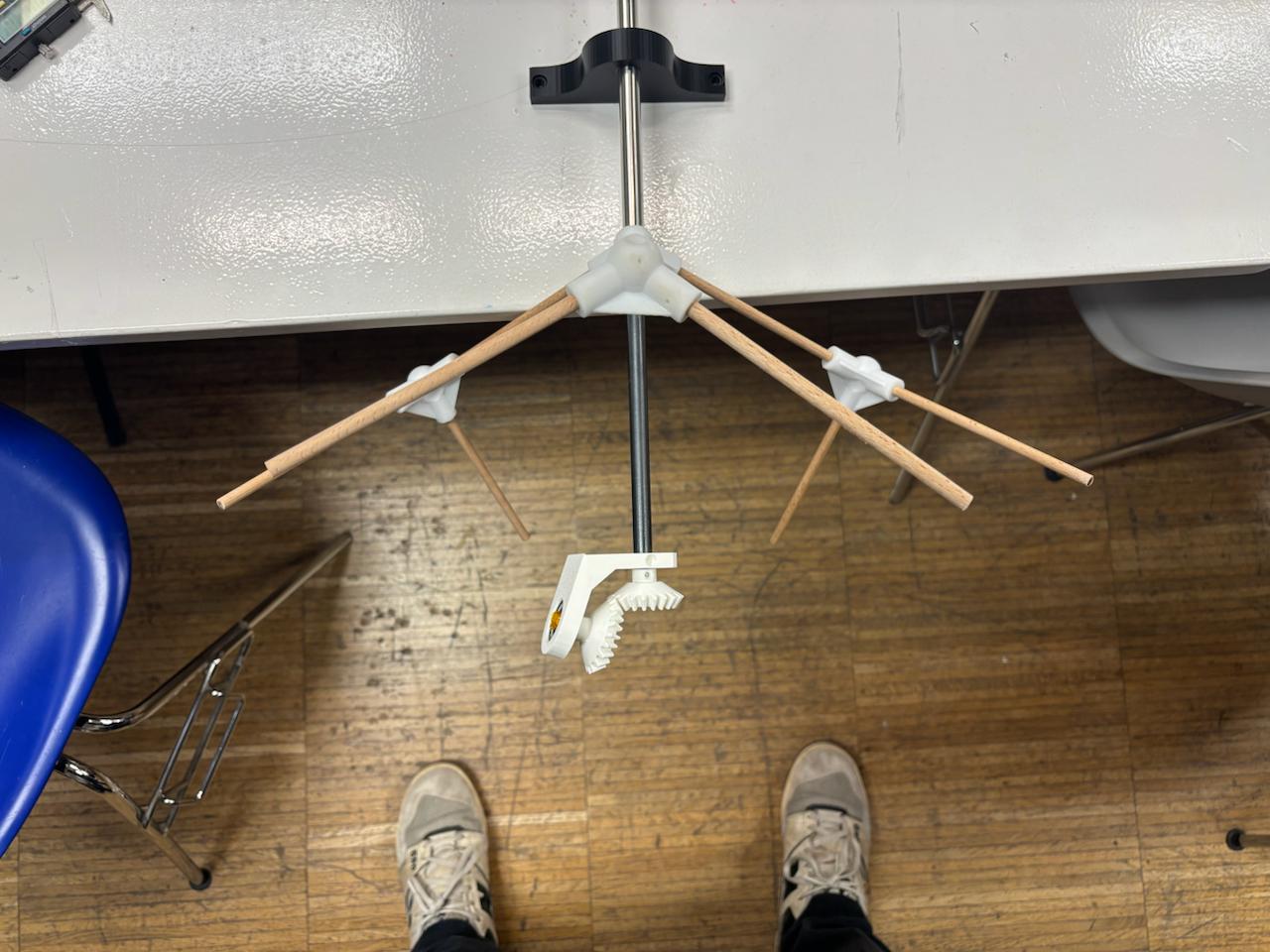
Milestone 1 — Single Shaft Rotation
The first milestone was deliberately minimal: get one shaft rotating, driven by one motor, and observe how every part of the system behaved under real motion.
This single test was actually testing several things at once:
- Grip — whether the resin-printed joint held firmly onto the outer driving shaft under rotation, without slipping
- Structural integrity — how the resin joint and wood rod structure as a whole responded to sustained rotational movement
- Gear retention — whether the gear and clamp system stayed seated on the shaft, or worked itself loose over time
- Meshing — how well the gear attached to the stepper motor meshed with the gear on the shaft, and what the resulting 1:2 gear reduction meant in practice for the rotation speed and for how the stepper needed to be programmed
- Rhythm — by adjusting the program, testing different rotational rhythms and observing how the motion felt
This was the minimal viable product — barely more than a motor, a gear, and a shaft. But it proved the core idea was mechanically sound. Everything that followed was about adding complexity on top of this working foundation: a second shaft, the bevel gear, the second geometry, the electronics, the touch input. Spiral development, one working layer at a time.
Milestone 2 — Two-Axis Mechanism Test, No Motors
With the single shaft proven, the second milestone tested the full three-shaft and bevel gear system together for the first time — manually, without motors, purely to see whether the mechanism itself worked.
This phase tested several critical aspects of the shaft design at once:
- Friction on the outer shaft — having proven the outer shaft worked in isolation, this test checked how it behaved once the middle shaft was introduced inside it, and whether the added friction surface affected its rotation
- Positioning the middle tube — the middle tube needed to sit precisely at the center of the structure as a fixed scaffold, giving the bevel gear bracket something stable to latch onto
- Driving the inner shaft through the middle tube — testing how the inner shaft rotated within the middle tube and drove the bevel gears. A key detail here: small rings were cut and slid onto the inner shaft to center it precisely within the middle tube. Maintaining this center point mattered — it determines the exact height at which the stepper motor sits, which in turn determines whether the bevel gears mesh correctly
- Bevel gear meshing — testing the bevel pair under real rotation revealed they needed slightly more clearance to avoid jamming. The fix was to offset both bevel gears 0.3mm apart from each other while maintaining the shared apex point of their pitch cones. This small adjustment resolved the jamming completely.
This was the first time I could observe the two geometries — and the mechanism driving them — interacting with each other as a complete system. Watching both axes move together, even by hand, confirmed that the underlying mechanical logic was sound and ready for motorisation.
Milestone 3 — Full Assembly: Two Driven Axes and Capacitive Touch Control
With both axes proven mechanically, the third milestone brought everything together into a single working system: two independent steppers driving the two axes, both powered and controlled by the pentagon motherboard, with capacitive touch as the input layer.
Driving both axes
This phase moved from manual rotation to motorized control. Both steppers — one for the outer shaft, one for the inner shaft driving the bevel gears — were connected to their driver circuits on the pentagon board and run simultaneously for the first time. This meant the two independent rotations, each previously tested in isolation, now had to coexist: running at the same time, on the same structure, powered from the same board, without interfering with each other mechanically or electrically.
Capacitive touch input
In parallel, this milestone tested the capacitive touch pads as the actual input mechanism for controlling the motion. This involved:
Testing each of the rotary pad segments individually to confirm they were reading capacitance correctly once connected to the full board Setting the touch thresholds — calibrating the values that distinguish a deliberate touch from background noise, the same empirical method developed earlier (moving a hand around the pad and observing the changing raw values) Testing how a touch input translated into movement — confirming that a detected touch position on the pad correctly triggered and influenced the rotation of the mechanism
This was the first point where input and output existed in the same loop: touch the pad, and the sculpture responds. A small but significant step — the beginning of the piece behaving as an interactive object rather than just a mechanical demonstration.
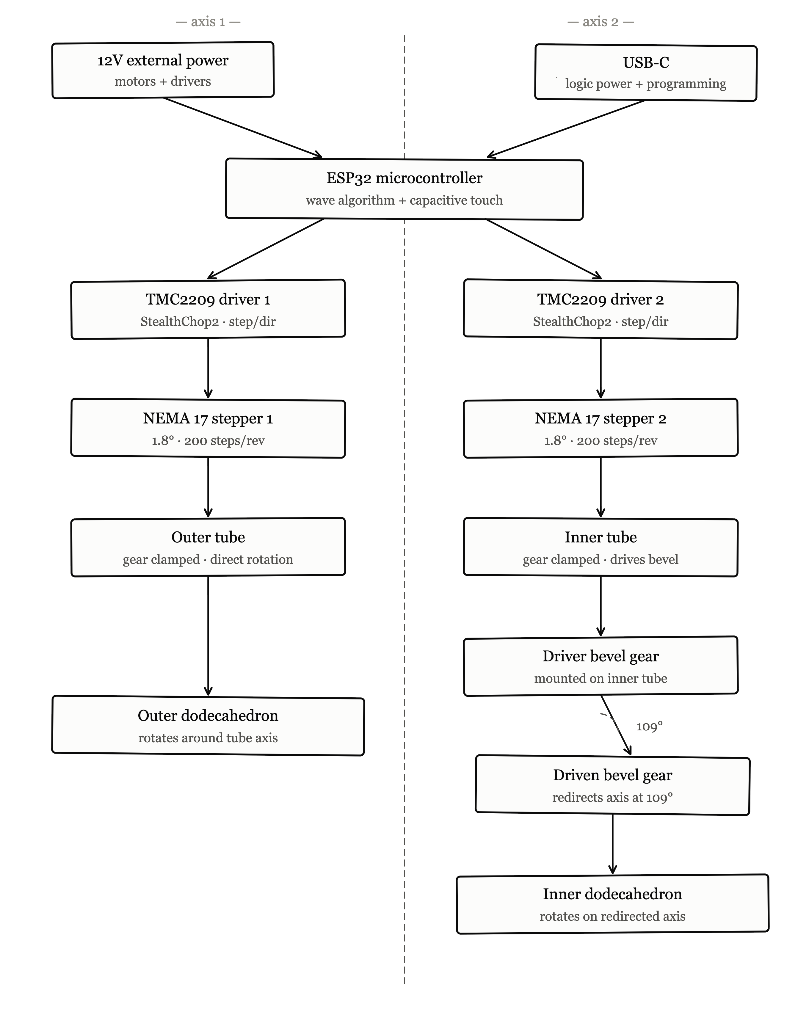
Simple Block Diagram