MY FINAL PROJECT - OBSERVER ARM
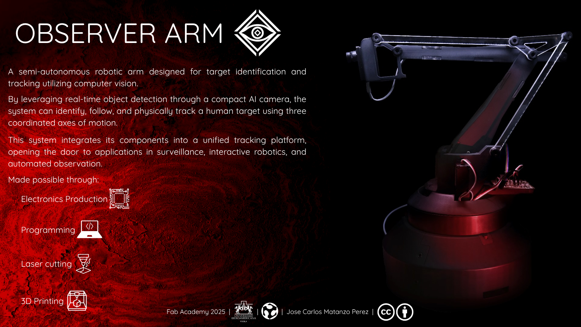
I welcome you to the culmination of my work in FabAcademy 2025, the Observer Arm, a robot arm with computer vision capabilities, tasked with identifying and tracking an objective.
Summary
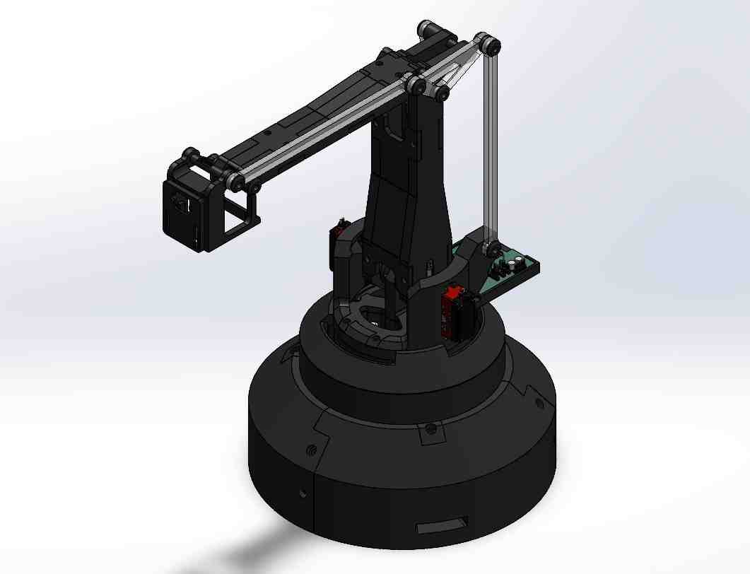
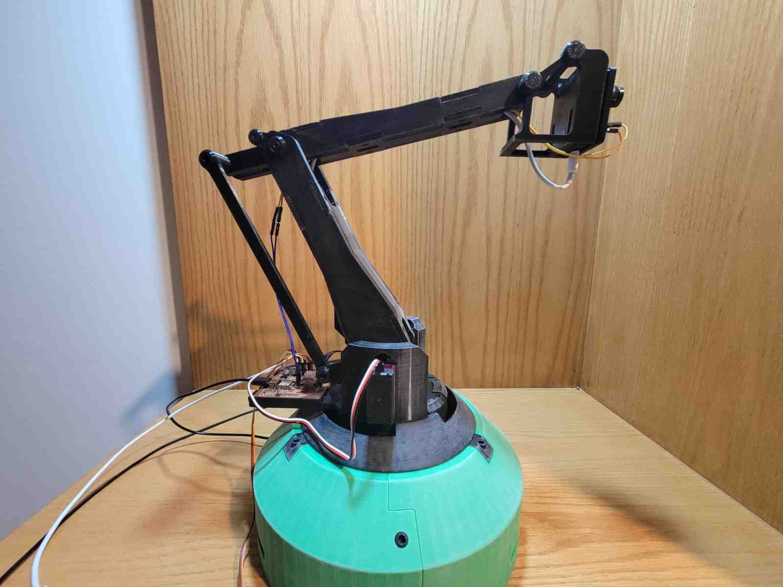
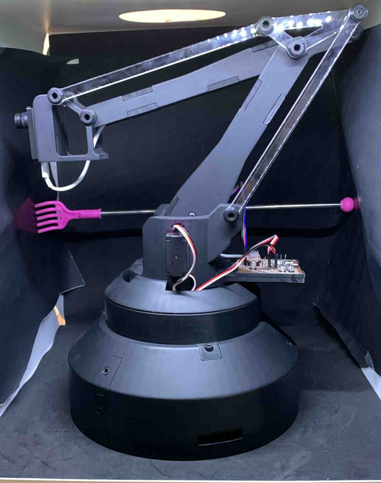
My final project, the Observer Arm, is a computer vision guided robotic arm capable of detecting, tracking, and physically aligning itself with a human subject in real time. Controlled through an OpenMV H7 camera and a custom-designed XIAO RP2040-based PCB, the system integrates servo and stepper motors for full 3-axis movement: height, extension, and rotation.
This concept was inspired by vision-based robotics such as the JetMax, and its structure draws from proven parallelogram-based mechanisms often used in precision robotic arms, with my main inspiration being the article Nguyen TP, Nguyen H, Ngo T. Design and implementation of a field robot using a parallelogram mechanism. Science Progress. 2024;107(4). The project is informed by research and documentation in open-source robotic communities, online tutorials, and mechanical design literature.
I designed the entire mechanical system from scratch, including the articulated joints, base, and end effector supports. I also created the PCB used to integrate the camera, servo motors, and stepper driver, and developed custom firmware to enable synchronized movement across all axes based on live visual input.
This is the current Bill Of Materials:
Mechanical Components
| Item | Details | Quantity | Unit Price | Source / Link |
|---|---|---|---|---|
| PLA Filament | Black PLA | ~1.6 kg | $23.50 per kg | Link |
| Axial Ball Bearing | 78mm OD, 40mm ID, 26mm H | 1 | $5.68 | Link |
| Nema 17 planetary gearbox | 10:1 Ratio | 1 | $11.00 | Link |
| M3 Screws & Nuts | Mixed lengths | 10 | N/A | N/A |
| M5 Screws | 12mm | 9 | N/A | N/A |
Electronic Components (External to PCB)
| Component | Specification | Quantity | Unit Price | Source / Link |
|---|---|---|---|---|
| DS3218 Servo Motor | 20kg high torque | 2 | $10.03 | Link |
| NEMA 17 Stepper Motor | 40mm | 1 | $8.21 | Link |
| OpenMV H7 Camera | with FOMO model support | 1 | $80.33 | Link |
| D-100A Power Supply | 5V / 12V dual output | 1 | $23.03 | Link |
| Dupont Cables | Assorted | 16 | $4.08 for 120 unit bundle | Link |
| USB-C to USB-C Cable | Data + power | 1 | N/A | N/A |
| Micro USB to USB-A Cable | Data + power | 1 | N/A | N/A |
Custom V3 PCB Components
| Component | Specification / Package | Quantity | Unit Price | Source / Link |
|---|---|---|---|---|
| XIAO RP2040 | — | 1 | $4.64 | Link |
| A4988 Driver | — | 1 | $2.20 | Link |
| Resistor | 4700Ω, 1260 | 2 | N/A | N/A |
| Resistor | 1000Ω, 1260 | 1 | N/A | N/A |
| Resistor | 10000Ω, 1260 | 1 | N/A | N/A |
| LED | 1260 | 1 | N/A | N/A |
| Capacitor | 10nF, 0603 | 4 | N/A | N/A |
| Electrolytic Capacitor | 10µF | 1 | N/A | N/A |
| Electrolytic Capacitor | 22µF | 1 | N/A | N/A |
| Electrolytic Capacitor | 220µF | 1 | N/A | N/A |
| 3.3V Voltage Regulator | — | 1 | N/A | N/A |
| Push Button | — | 1 | N/A | N/A |
| Pin Header | 2-pin | 6 | N/A | N/A |
| Pin Header | 3-pin | 3 | N/A | N/A |
| Pin Header | 4-pin | 1 | N/A | N/A |
All of the common materials whose prices and links are not included in the BOM where already in my possession or provided by my local instructor.
Total cost of the components that I bought is estimated at $205 before taxes and shipping.
The system integrates several subsystems: 3D-printed structural parts, custom electronics, and firmware developed in Python and the Arduino IDE. The project utilized multiple digital fabrication techniques, including 3D printing, laser cutting and CNC milling for the PCB. Finishing processes such as sanding and painting were applied to enhance the professional aesthetic.
Throughout development, I tackled key questions such as how to manage real-time control using camera feedback, how to balance torque and speed in motor selection, and how to coordinate multiple degrees of freedom with smooth motion. While many subsystems worked well, challenges like insufficient motor torque and mechanical redesigns shaped the iteration process.
The project was evaluated on its ability to autonomously detect and track humans, align its mechanical arm precisely, and integrate all subsystems into a cohesive unit. These goals were met successfully, with room for improvement in the fields of motor control and smoothness, and greater degrees of freedom utilizing a slip ring for cable management. The broader implication of the Observer Arm is its potential use in surveillance, documentation, interaction, and education, all with an accessible, replicable, and open-source spirit.
Key weekly developments:
- Week 02: Computer Aided Design
- Week 08: Electronics Production
- Week 09: Input Devices
- Week 10: Output Devices
- Week 11: Networking and Communications
- Week 15: System Integration
- Week 17: Applications and Implications
- Week 18: Invention, Intellectual Property and Income
1. Conception
The initial inspiration for the Observer Arm came from a rather personal event, a break-in at my family's business last year. This unsettling experience sparked the idea of creating an accessible, customizable system capable of assisting with surveillance and real-time target identification. I envisioned a piece of equipment that, while simple to manufacture, could be expanded upon to incorporate "deterrent" end effectors or additional functionalities based on user needs.
From this concept emerged the vision for an automated, camera-guided surveillance arm, a semi-autonomous robotic device that could visually detect and follow intruders or individuals in its environment. My goal was not only to build a functional prototype but to design a platform that could be easily replicated and modified. This focus on openness and modularity guided every decision, from the mechanical design to the electronic architecture.
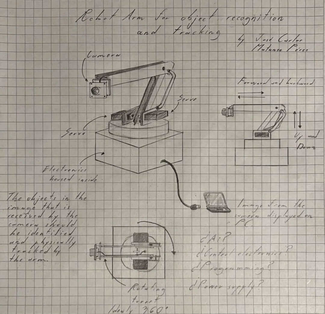
The first iterations began with a rough conceptual design sketch, gradually evolving into the first CAD models and system diagrams. These early drafts formed the backbone of what would later become a fully integrated robotic surveillance tool.
2. Mechanical Design
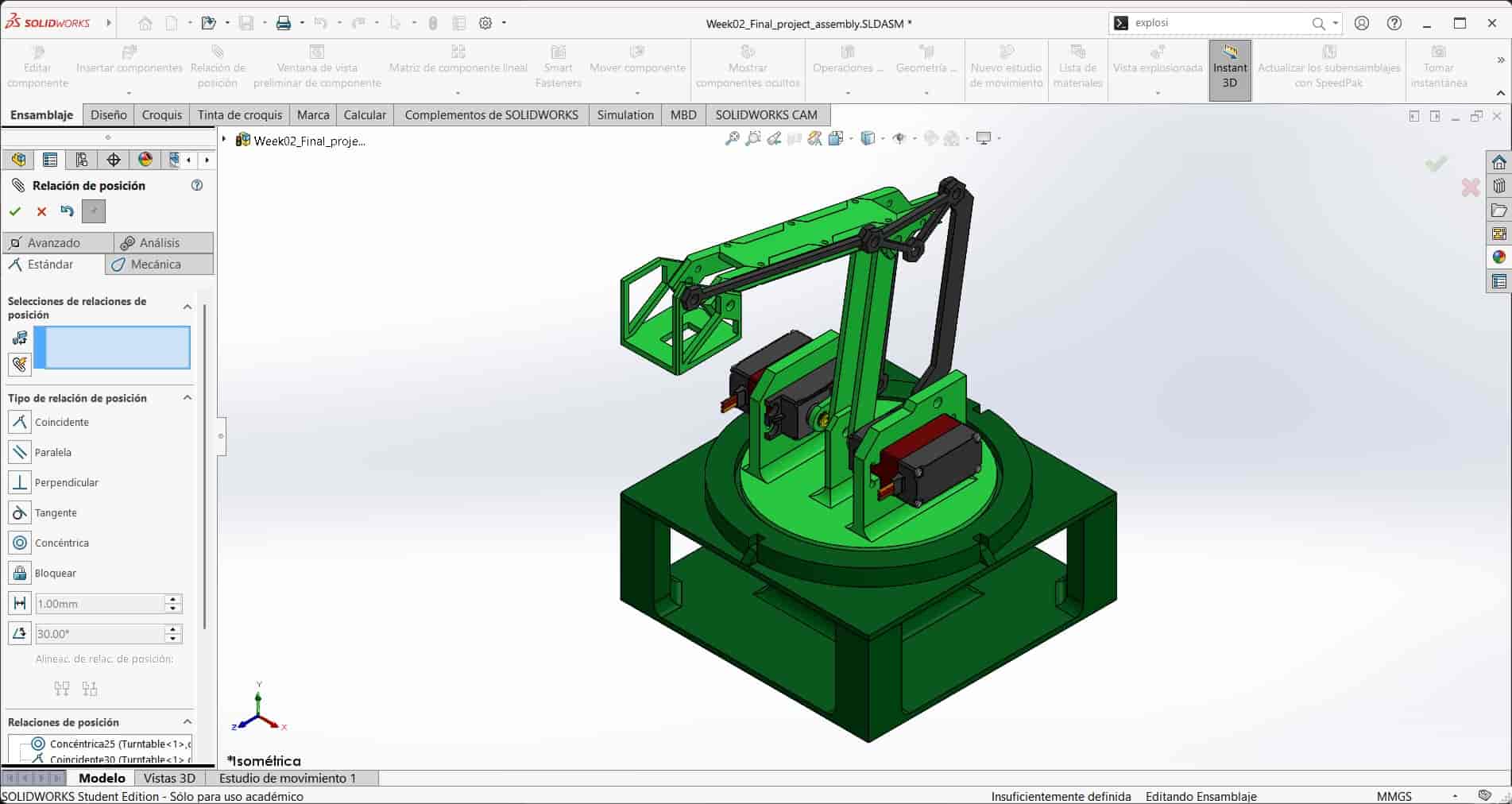
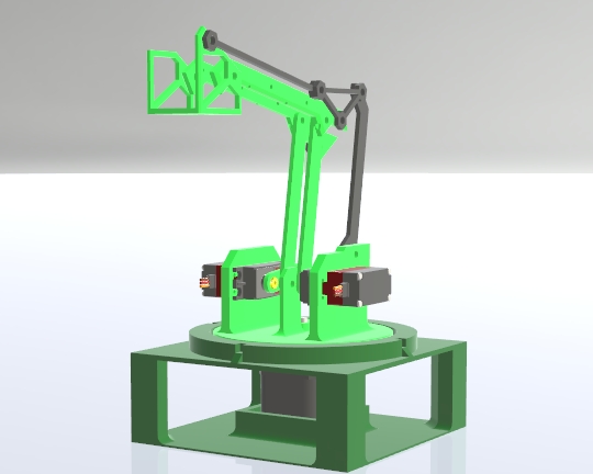
The mechanical development of the Observer Arm evolved significantly from its initial concept. The first design was created during Week 2: Computer-Aided Design, as a rushed prototype that, although smaller and somewhat crude, served as an initial grounded concept. This early version lacked proper proportions and did not implement the perfect parallelogram mechanism that would later become essential for the stability of the final arm.
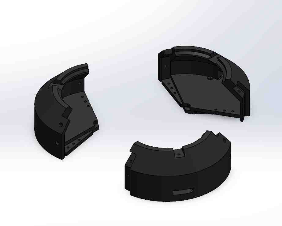
The refined mechanical design was developed from scratch, preserving only the core idea. It began with the creation of a three-part circular base, forming a 250 mm diameter dome. This base was engineered with modularity in mind, where each segment includes interlocking M5 slots for easier access to internal components, making assembly, maintenance and modifications easier.
Next, I designed the stepper motor mount, the largest single printed part in the entire system, made to accommodate the NEMA 17 stepper motor and its planetary gearbox. This piece includes a slot for a stepper cap and a seat for half of the axial ball bearing, both of which are press-fitted into place.
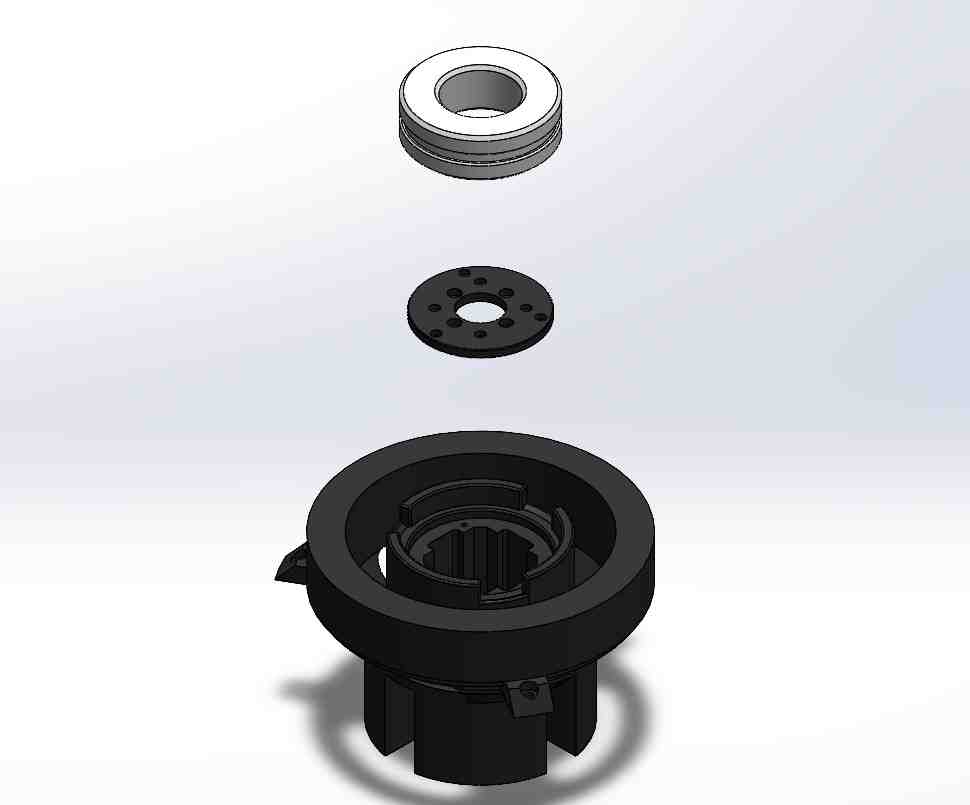
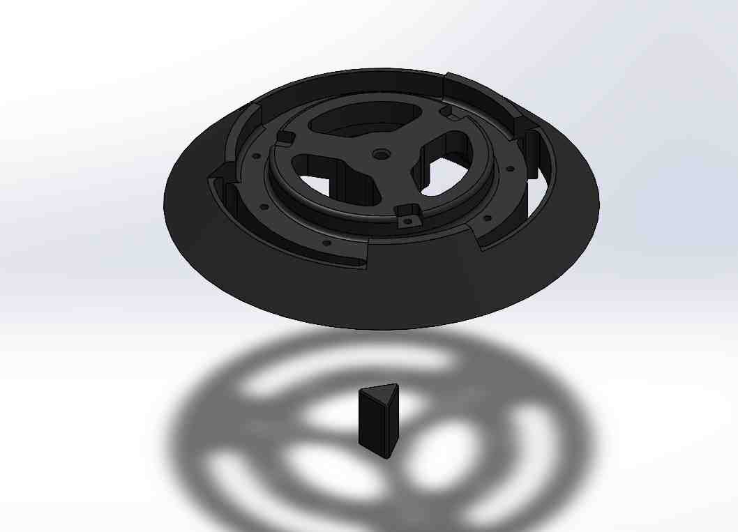
Above it sits the turntable, which carries the rotating section of the robot. It is aligned with the second half of the axial bearing and connects directly to the stepper shaft. The turntable and stepper mount both feature vertical cavities for internal cable routing. A central axial adapter allows for flexible motor configurations by swapping out a small coupler insert, avoiding the need to redesign larger structural parts.
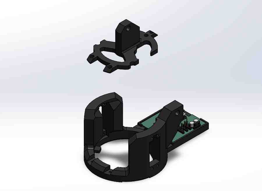
Stacked on the turntable is the servo motor mount, a cylindrical support featuring symmetrical mounts for two high-torque servos, fixed by pressure only. It also holds the PCB and includes connection points for both the main arm and the smaller parallelogram arms. Nestled between the servo mounts is the arm axis mount, which adds mechanical support for axial rotation and structural rigidity.
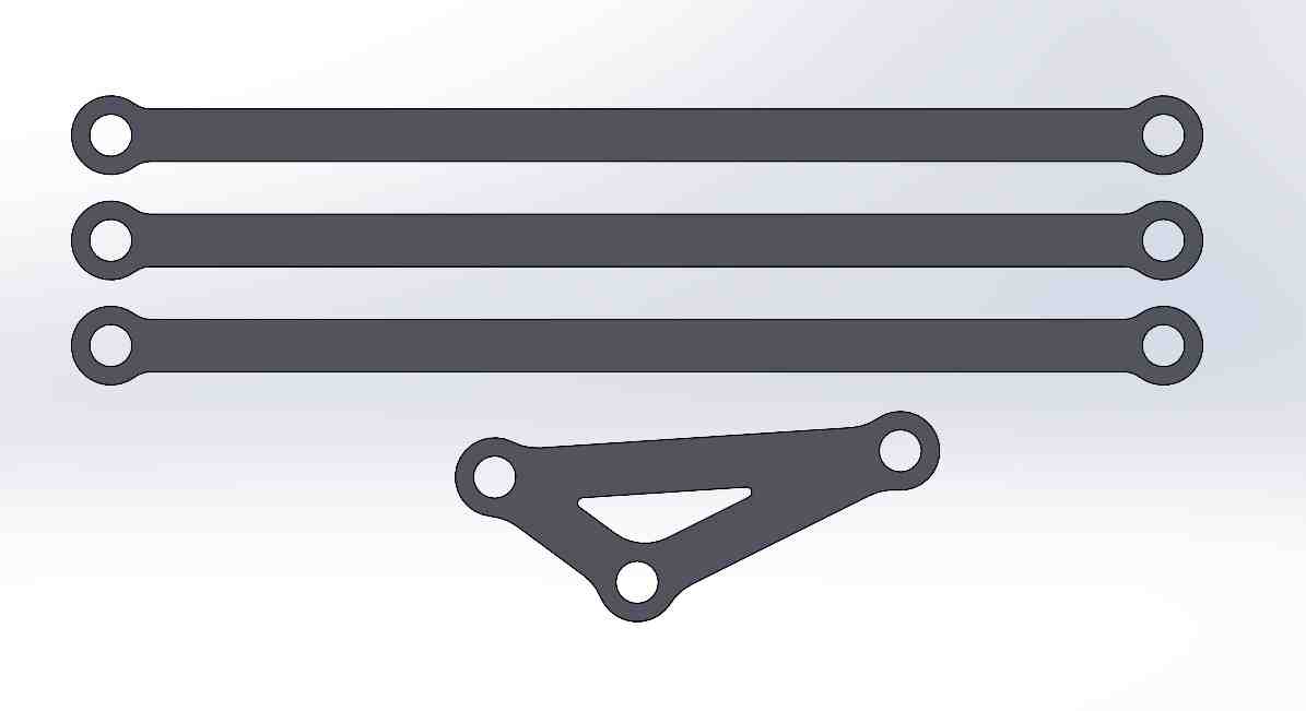
The arm itself consists of two articulated segments, each built from a pair of side frames and a pair of protective caps. The first segment is directly mounted to the servo base, while the second pivots from the first and is actuated by a two-bar servo linkage. This linkage features a laser-cut acrylic arm and implements the parallelogram mechanism to ensure that the camera remains level regardless of movement.
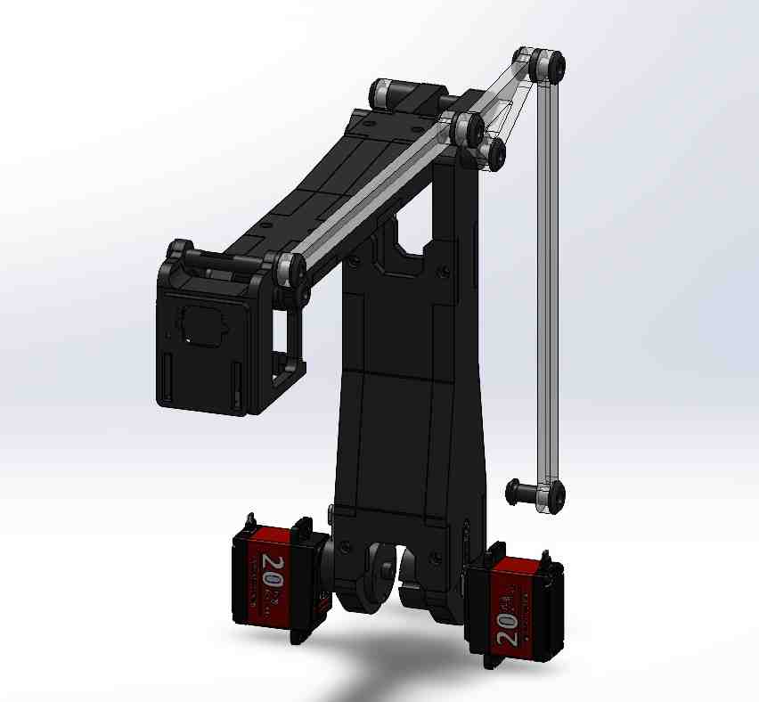
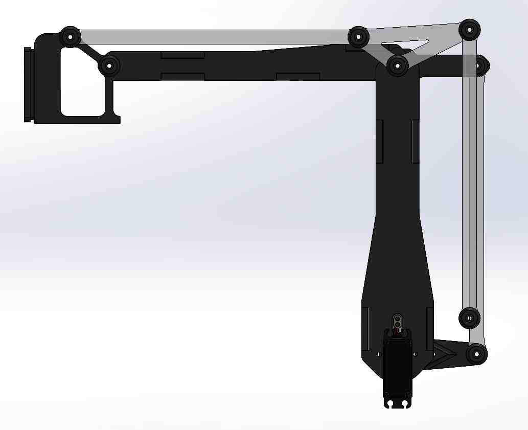
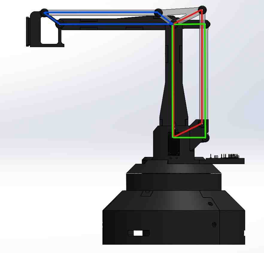
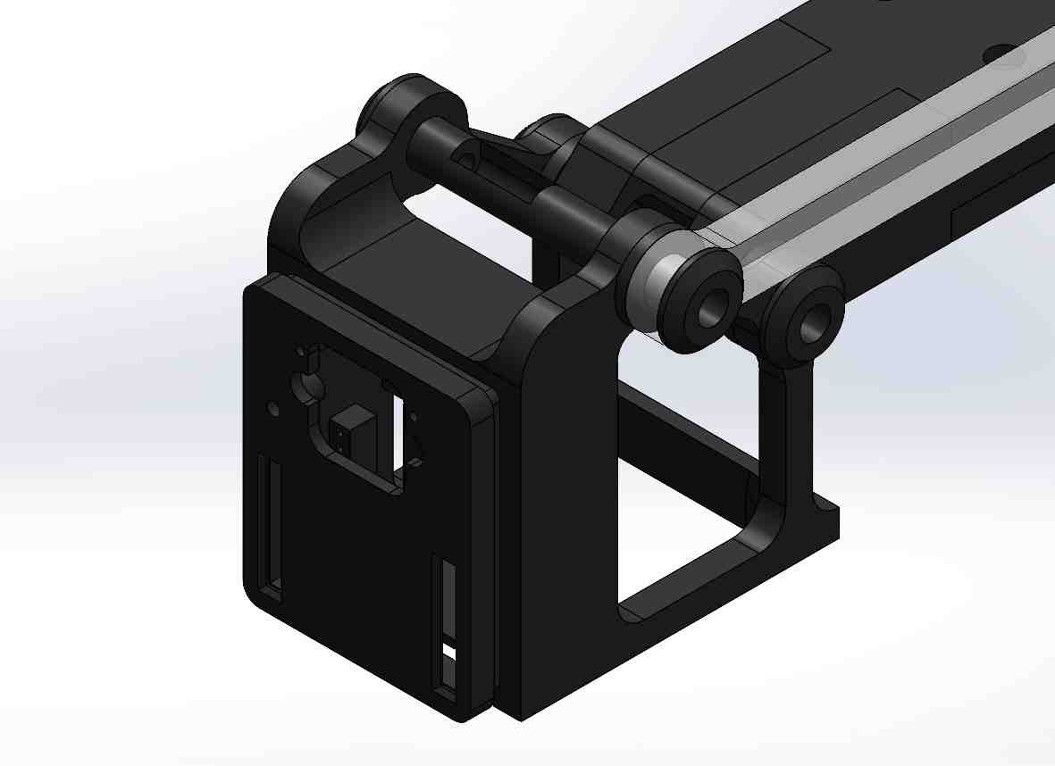
At the far end of the arm is the end effector, which is a custom-designed OpenMV H7 camera mount, reverse-engineered from official models. This mount includes dual pivot points and a cap for secure camera installation. Completing the parallelogram structure is a secondary triangle-shaped part and two additional acrylic arms on the right side of the assembly, providing full mechanical compensation for angular motion.
Altogether, the system includes eight pivot points fitted with modular axle assemblies, each composed of two parts joined with M3 screws. These allow for smooth, constrained rotation and robust mechanical articulation across the entire arm.
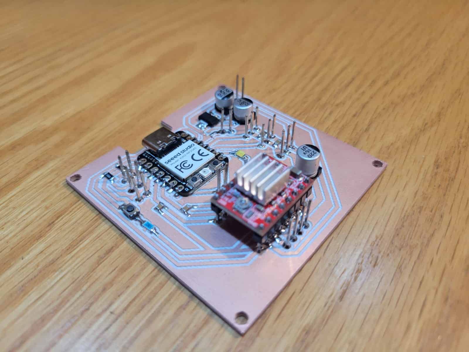
3. Electronics Design
The electronics behind the Observer Arm revolve around a custom-designed PCB, now in its third and most refined iteration, which I call V3. This board was conceived to serve as the central control unit of the system, integrating motor drivers, power management, and microcontroller interfaces in a compact and reliable layout.
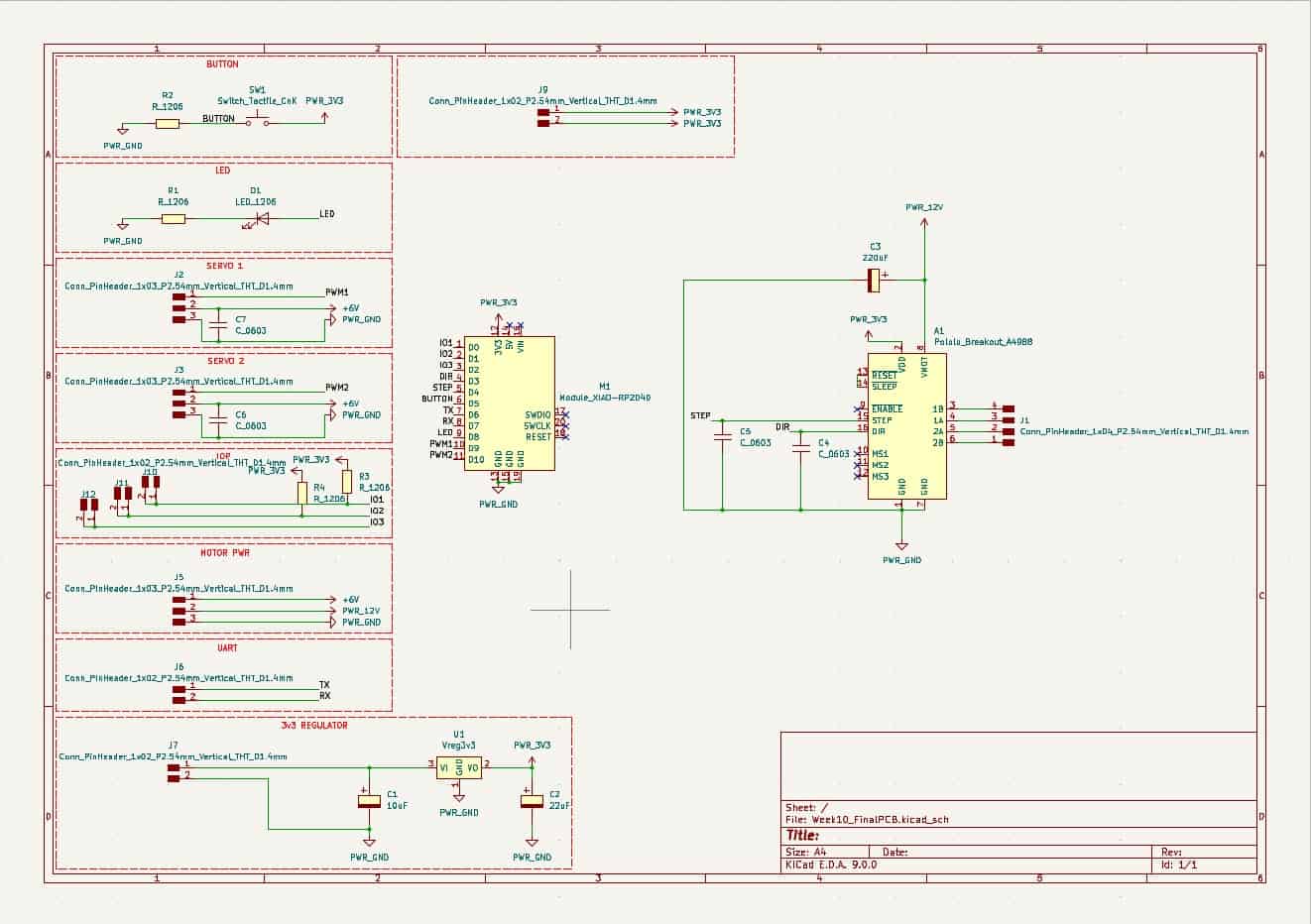
At its core is the Seeed Studio XIAO RP2040, selected for its small footprint, USB-C compatibility, and sufficient I/O capacity for the needs of the arm. Each version of the board included standard elements such as a push button for input and an LED indicator for output feedback, as well as a 3.3V voltage regulator supported by its required capacitors.
A crucial feature of the board is the direct integration of an A4988 stepper motor driver, with dedicated DIR and STEP lines connected to the XIAO, and decoupling capacitors, enabling precise control of the arm's rotational base. Power lines were routed separately to support both the stepper motor and the two high-torque servo motors. Proper I/O and ground headers were assigned for each device, maintaining modularity and simplifying debugging.
The PCB layout includes header pins for the remaining I/O lines on the RP2040, allowing future expansion and modular upgrades. Notably, the UART pins were clearly separated to ensure clean communication with the OpenMV H7 camera. Additionally, this V3 version includes accommodations for I2C communication, providing flexibility for future sensors or modules.
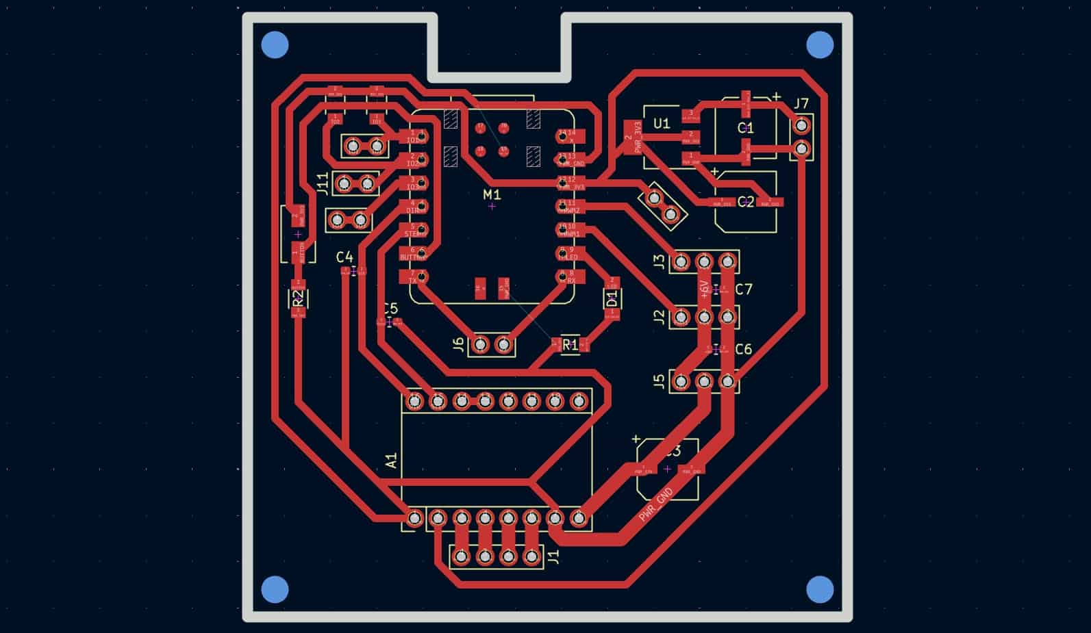
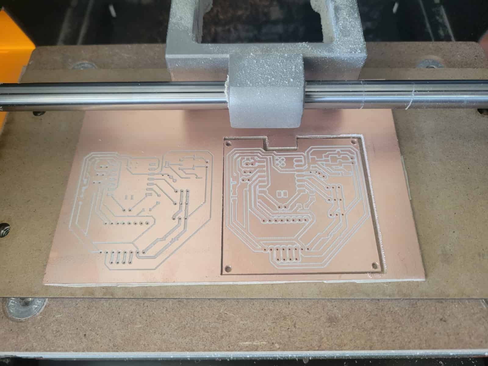
The board's evolution across three versions reflects a valuable learning process. Through each iteration, I improved both the schematic logic and the physical routing, resulting in a cleaner, more efficient, and manufacturable final product. The entire board was designed in KiCAD, with toolpaths generated using the mods.ce online platform, and fabricated on a Roland Monofab SRM-20 desktop milling machine as part of Week 11: Output Devices of the Fab Academy.
4. Manufacturing
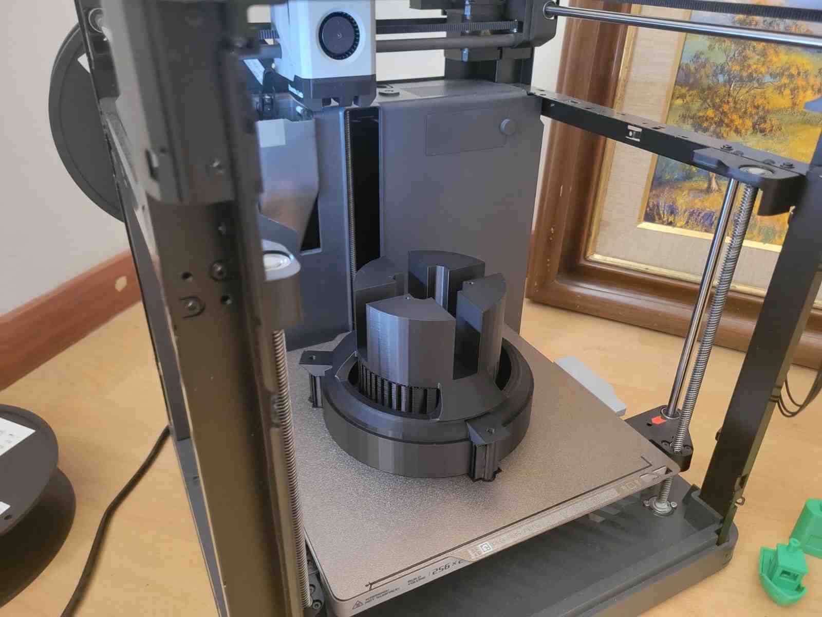
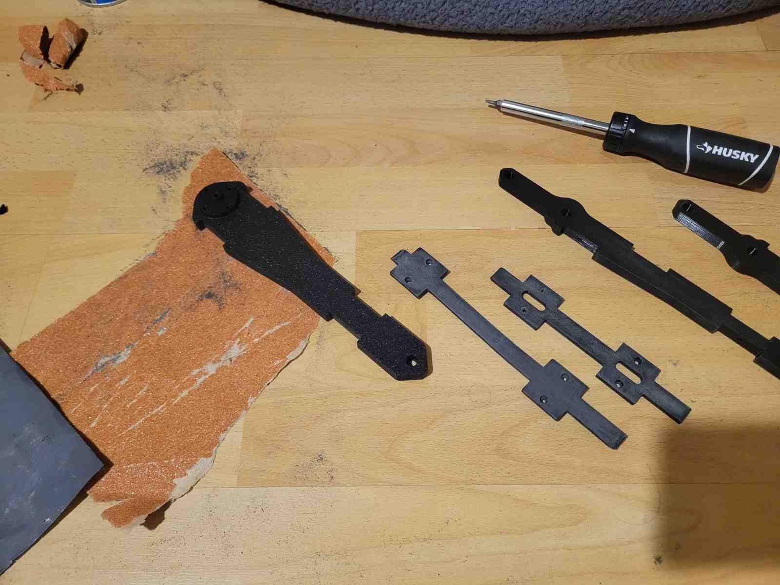
The manufacturing of the Observer Arm was centered around 3D printing, which served as the main method for prototyping and producing structural components. Over the course of development, I used approximately 2.5 kilograms of PLA plastic to fabricate, iterate, and refine every part of the arm and its mechanisms. This iterative cycle was essential, as several components required modifications or complete redesigns based on mechanical performance and assembly testing.
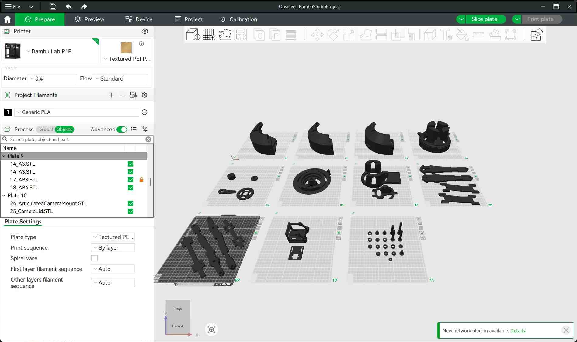
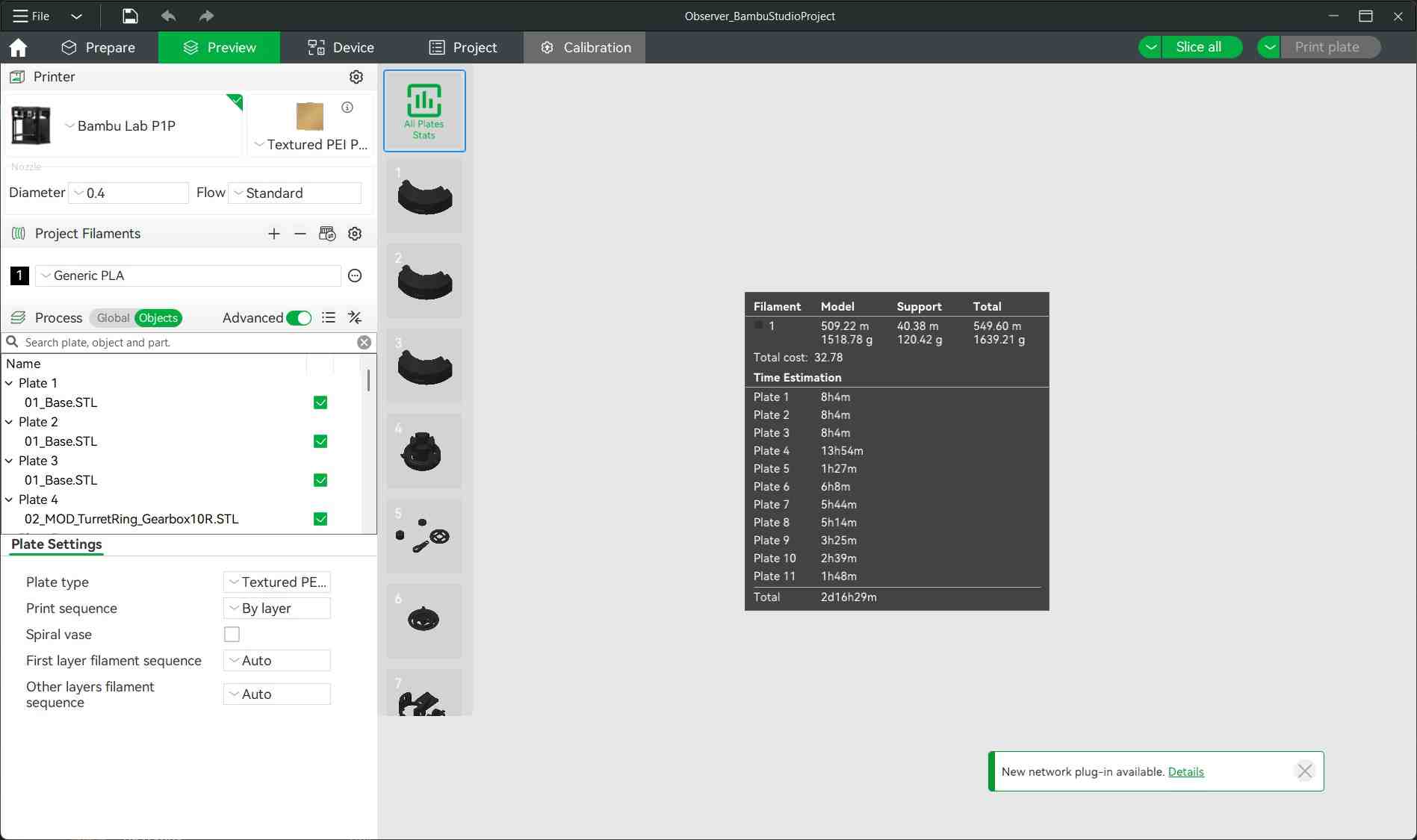
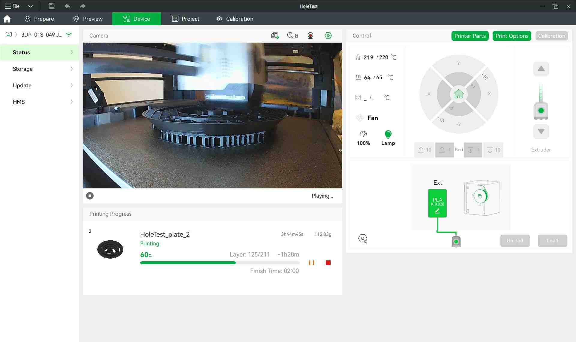
All 3D-printed parts were produced using a Bambu Lab P1P printer, configured with a 20% infill density for a balance between strength and material efficiency. Through experimentation, I discovered a critical slicer parameter that drastically improved the quality and removability of support structures: a Top Z Offset Distance of 0.275 mm. This setting allowed for clean removal of supports without damaging the parts, significantly improving print post-processing.
It was during this phase that I encountered a major design insight: my initial arm assembly was not functional, due to it not complying with the perfect parallelogram mechanism. After observing its flawed kinematics and conducting further research, I revised the geometry of the arm to follow true parallelogram principles, ensuring constant orientation of the end effector throughout the arm's range of motion.
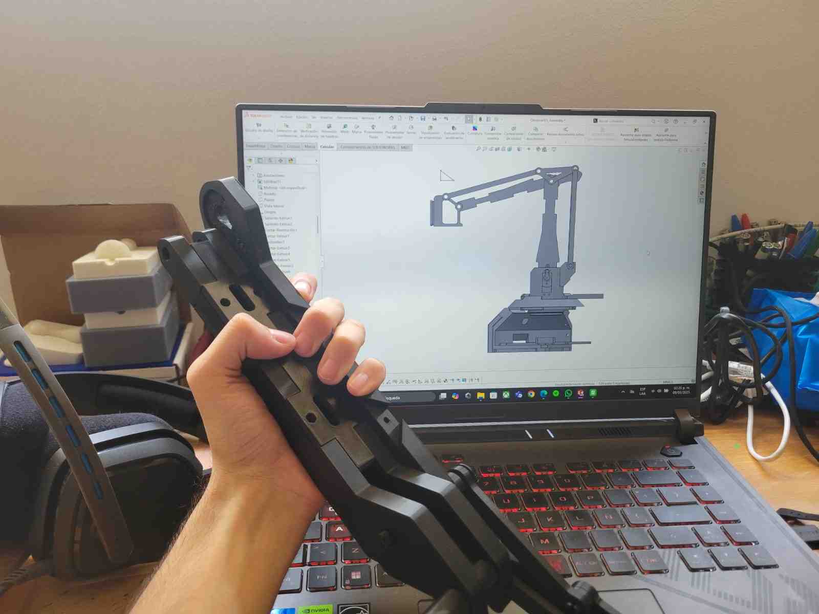
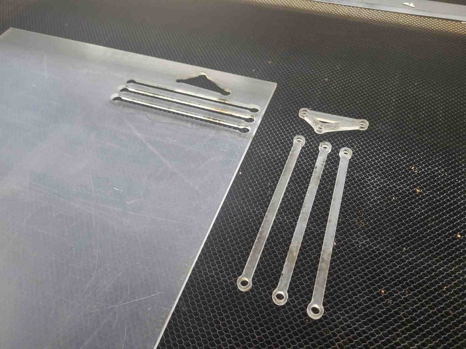
To test fit and alignment of the linkage elements, I first 3D printed versions of the acrylic bars before committing to final fabrication. Once verified, I converted the top-view outlines of the finalized linkage design into DXF format and used it to laser cut the components from 6 mm thick acrylic. The contrast between additive and subtractive manufacturing techniques proved highly complementary, allowing for precision in mechanical linkages while preserving flexibility in the overall structure and having aesthetically distinct components that complement each other.
Once all components were fabricated, I proceeded to final assembly and fit verification, confirming that the motor mounts, axial supports, and pivot points were correctly aligned. This stage was pivotal in preparing the system for final integration and programming.
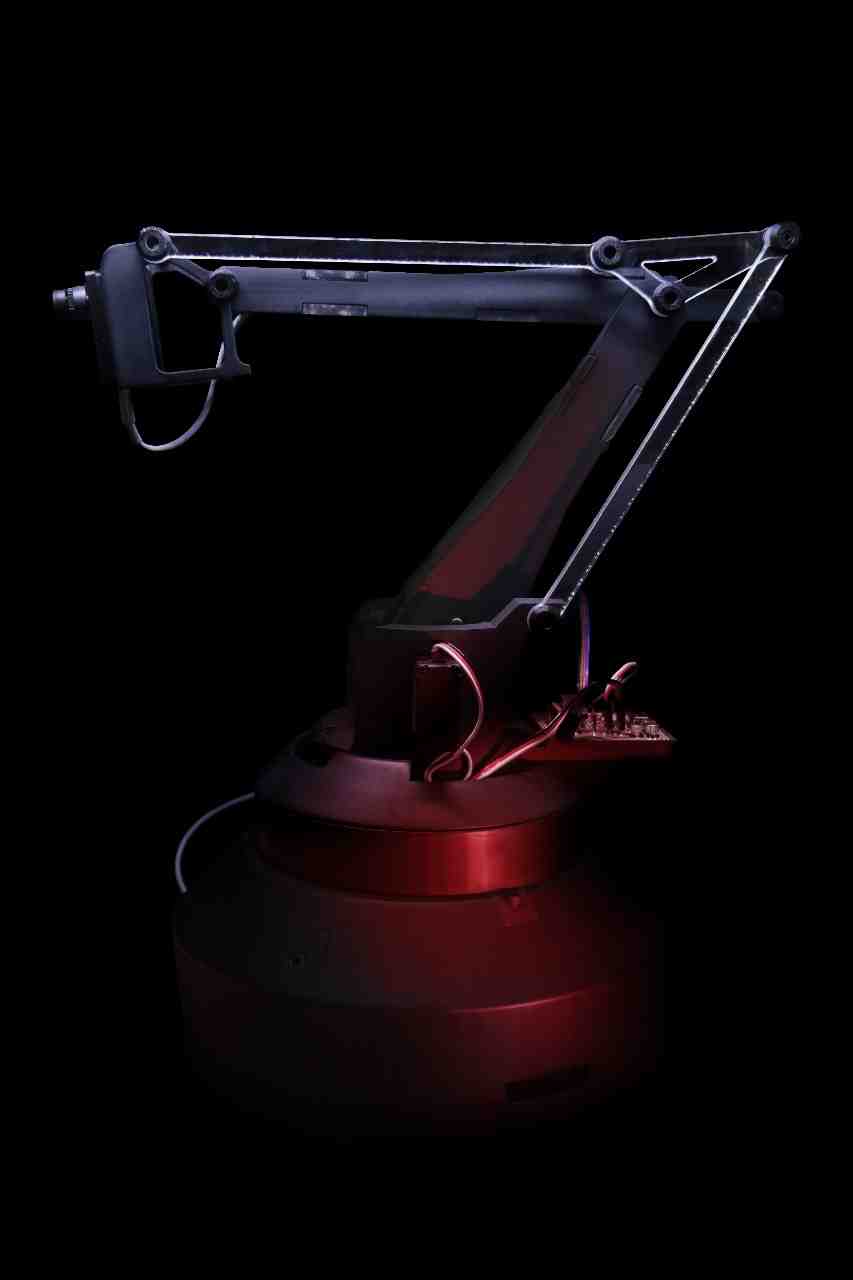
5. Finishing
To achieve a polished and professional look for the Observer Arm, I undertook a thorough surface finishing process. This began with progressive sanding using 60, 120, 220, 360, and 600 grit sandpaper, applied in that order. Each successive grit helped to remove print lines, smooth edges, and prepare the surface for painting.
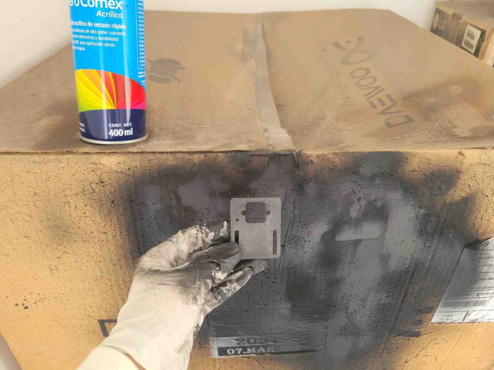
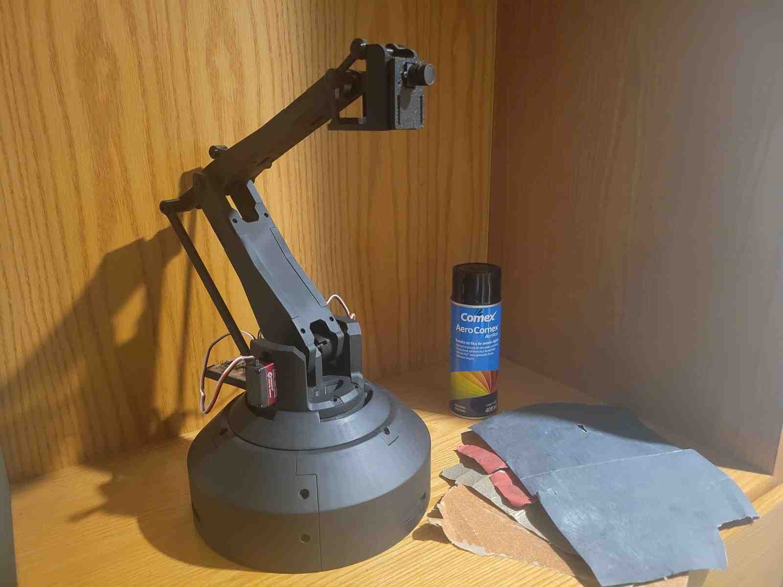
Once the sanding was complete, I applied a coat of acrylic enamel spray paint to give the parts a uniform and refined appearance. This not only improved the visual appeal of the arm but also offered basic protection against scratches and environmental wear.
After the paint had dried, I repeated a final round of sanding using 360 and 600 grit sandpaper to enhance the smoothness of the finish and remove any imperfections introduced during painting. This careful post-processing resulted in a sleek, matte-like surface that complements the mechanical functionality with aesthetic quality.
6. Programming
The programming of my final project is comprised of two sepparate codes, that work with each other through serial communications in order to achieve the full functionality of the system. The code on the OpenMV h7 camera is tasked with identifying and tracking the target, after which it will communicate said target's positional data to the XIAO RP2040. The XIAO's code calculates the difference between the center of the camera's window and the target's position, and controls the motors of the robot to physically align the target with the center.
6.1. OpenMV H7 Programming
The OpenMV H7 camera serves as the visual input system for the Observer Arm. It detects and tracks humans using a FOMO-based face detection model and transmits coordinates to the microcontroller for motion control. The camera also features an ACK/NACK communication system to ensure command delivery reliability.
import sensor
import time
import math
import image
import pyb
import ml
from ml.utils import NMS

sensor.reset()
sensor.set_pixformat(sensor.RGB565)
sensor.set_framesize(sensor.QVGA)
sensor.skip_frames(time=2000)

min_confidence = 0.95
threshold_list = [(math.ceil(min_confidence * 255), 255)]

model = ml.Model("fomo_face_detection")
uart = pyb.UART(3, 115200)

def fomo_post_process(model, inputs, outputs):
    n, oh, ow, oc = model.output_shape[0]
    nms = NMS(ow, oh, inputs[0].roi)
    for i in range(oc):
        img = image.Image(outputs[0][0, :, :, i] * 255)
        blobs = img.find_blobs(threshold_list, x_stride=1, area_threshold=1, pixels_threshold=1)
        for b in blobs:
            rect = b.rect()
            x, y, w, h = rect
            score = img.get_statistics(thresholds=threshold_list, roi=rect).l_mean() / 255.0
            nms.add_bounding_box(x, y, x + w, y + h, score, i)
    return nms.get_bounding_boxes()

centerX, centerY = 160, 120
clock = time.clock()
last_seen = pyb.millis()

# ACK/NACK system
waiting_for_ack = False
last_command_time = 0
ack_timeout = 500
command_buffer = ""

def send_command_and_wait_ack(command):
    global waiting_for_ack, last_command_time, command_buffer
    uart.write(command + "\n")
    waiting_for_ack = True
    last_command_time = pyb.millis()
    command_buffer = command

def check_for_ack():
    global waiting_for_ack
    if uart.any():
        response = uart.readline().decode().strip()
        if response == "OK":
            waiting_for_ack = False
            return True
        elif response == "NACK":
            waiting_for_ack = False
            return False
    return None

def handle_ack_timeout():
    global waiting_for_ack
    if waiting_for_ack and (pyb.millis() - last_command_time > ack_timeout):
        waiting_for_ack = False
        return True
    return False

while True:
    clock.tick()
    img = sensor.snapshot()
    person_detected = False

    # ACK/NACK handling
    ack_result = check_for_ack()
    handle_ack_timeout()

    img.draw_line(centerX - 10, centerY, centerX + 10, centerY, color=(0, 255, 0), thickness=1)
    img.draw_line(centerX, centerY - 10, centerX, centerY + 10, color=(0, 255, 0), thickness=1)
    img.draw_string(centerX - 30, centerY + 15, f"Center: ({centerX},{centerY})", color=(0, 255, 0), scale=1)

    if not waiting_for_ack:
        for i, detection_list in enumerate(model.predict([img], callback=fomo_post_process)):
            if i == 0 or not detection_list:
                continue

            for (x, y, w, h), score in detection_list:
                center_x = math.floor(x + w / 2)
                center_y = math.floor(y + h / 2)
                area = w * h

                img.draw_rectangle((x, y, w, h), color=(255, 0, 0), thickness=2)
                img.draw_circle((center_x, center_y, 8), color=(255, 0, 0), thickness=2)
                img.draw_string(x, y - 12, f"({center_x},{center_y})", color=(255, 255, 0), scale=1)
                img.draw_string(x, y + h + 2, f"Conf: {score:.2f}", color=(255, 255, 0), scale=1)
                img.draw_string(x, y + h + 14, f"Area: {area}", color=(255, 255, 0), scale=1)
                dx = center_x - centerX
                dy = center_y - centerY
                img.draw_string(x, y + h + 26, f"Offset: ({dx:+d},{dy:+d})", color=(0, 255, 255), scale=1)
                img.draw_line(centerX, centerY, center_x, center_y, color=(255, 0, 255), thickness=1)
                img.draw_string(5, 5, "TARGET LOCKED", color=(0, 255, 0), scale=2)

                send_command_and_wait_ack(f"TRACK:{center_x}:{center_y}:{area}")
                person_detected = True
                last_seen = pyb.millis()
                break  # only one detection per loop

    if not person_detected and (pyb.millis() - last_seen > 700) and not waiting_for_ack:
        send_command_and_wait_ack("NO_PERSON")
        img.draw_string(5, 5, "SEARCHING...", color=(255, 255, 0), scale=2)

    img.draw_string(img.width() - 80, img.height() - 15, f"FPS: {clock.fps():.1f}", color=(255, 255, 255), scale=1)
1. Camera Setup and Model Initialization
import sensor
import time
import math
import image
import pyb
import ml
from ml.utils import NMS

sensor.reset()
sensor.set_pixformat(sensor.RGB565)
sensor.set_framesize(sensor.QVGA)
sensor.skip_frames(time=2000)
This section imports all the necessary libraries for image acquisition, math operations, serial communication, and machine learning model inference. Notably, the ml library handles the FOMO object detection model, and pyb allows access to UART for hardware communication.
The second half of this block initializes the OpenMV sensor. It sets the pixel format to RGB565 and the frame size to QVGA (320x240), providing a balance between detail and performance. The camera is given 2 seconds to stabilize.
2. Model Loading and Threshold Setup
min_confidence = 0.95
threshold_list = [(math.ceil(min_confidence * 255), 255)]

model = ml.Model("fomo_face_detection")
uart = pyb.UART(3, 115200)
We define the minimum confidence level for detections (95%) and load the pre-trained FOMO model designed for face detection. A UART connection is established on UART3 at 115200 baud to communicate with the XIAO microcontroller.
3. FOMO Post-Processing Function
def fomo_post_process(model, inputs, outputs):
    n, oh, ow, oc = model.output_shape[0]
    nms = NMS(ow, oh, inputs[0].roi)
    for i in range(oc):
        img = image.Image(outputs[0][0, :, :, i] * 255)
        blobs = img.find_blobs(threshold_list, x_stride=1, area_threshold=1, pixels_threshold=1)
        for b in blobs:
            rect = b.rect()
            x, y, w, h = rect
            score = img.get_statistics(thresholds=threshold_list, roi=rect).l_mean() / 255.0
            nms.add_bounding_box(x, y, x + w, y + h, score, i)
    return nms.get_bounding_boxes()
This function processes the model's output. It applies Non-Maximum Suppression (NMS) to eliminate overlapping detections and retrieve the most relevant bounding boxes from the detection heatmap output of the FOMO model.
4. Tracking Variables and Communication State
centerX, centerY = 160, 120
clock = time.clock()
last_seen = pyb.millis()

# ACK/NACK system
waiting_for_ack = False
last_command_time = 0
ack_timeout = 500
command_buffer = ""
We define the frame center and initialize the tracking timer. Variables for handling ACK/NACK communication are declared to ensure that commands are acknowledged and retransmitted if needed.
5. Communication Functions
def send_command_and_wait_ack(command):
    global waiting_for_ack, last_command_time, command_buffer
    uart.write(command + "\n")
    waiting_for_ack = True
    last_command_time = pyb.millis()
    command_buffer = command

def check_for_ack():
    global waiting_for_ack
    if uart.any():
        response = uart.readline().decode().strip()
        if response == "OK":
            waiting_for_ack = False
            return True
        elif response == "NACK":
            waiting_for_ack = False
            return False
    return None

def handle_ack_timeout():
    global waiting_for_ack
    if waiting_for_ack and (pyb.millis() - last_command_time > ack_timeout):
        waiting_for_ack = False
        return True
    return False
These functions manage sending commands and monitoring for acknowledgment. If no ACK is received within 500 ms, the system resets its waiting state, ready to resend the command.
6. Main Loop: Frame Capture and Detection
while True:
    clock.tick()
    img = sensor.snapshot()
    person_detected = False

    # ACK/NACK handling
    ack_result = check_for_ack()
    handle_ack_timeout()
The loop begins by capturing a new frame and resetting the detection flag. We then check for any ACK or NACK responses from the microcontroller.
7. Visual Aids and Detection Display
    img.draw_line(centerX - 10, centerY, centerX + 10, centerY, color=(0, 255, 0), thickness=1)
    img.draw_line(centerX, centerY - 10, centerX, centerY + 10, color=(0, 255, 0), thickness=1)
    img.draw_string(centerX - 30, centerY + 15, f"Center: ({centerX},{centerY})", color=(0, 255, 0), scale=1)
Crosshairs and center coordinates are displayed for debugging and visual alignment with the camera's frame center.
8. Detection and Target Communication
    if not waiting_for_ack:
        for i, detection_list in enumerate(model.predict([img], callback=fomo_post_process)):
            if i == 0 or not detection_list:
                continue

            for (x, y, w, h), score in detection_list:
                center_x = math.floor(x + w / 2)
                center_y = math.floor(y + h / 2)
                area = w * h
When not waiting for an ACK, the image is analyzed using the FOMO model. The position and size of the detected target are calculated.
9. Detection Annotations and Target Tracking
                img.draw_rectangle((x, y, w, h), color=(255, 0, 0), thickness=2)
                img.draw_circle((center_x, center_y, 8), color=(255, 0, 0), thickness=2)
                img.draw_string(x, y - 12, f"({center_x},{center_y})", color=(255, 255, 0), scale=1)
                img.draw_string(x, y + h + 2, f"Conf: {score:.2f}", color=(255, 255, 0), scale=1)
                img.draw_string(x, y + h + 14, f"Area: {area}", color=(255, 255, 0), scale=1)
                dx = center_x - centerX
                dy = center_y - centerY
                img.draw_string(x, y + h + 26, f"Offset: ({dx:+d},{dy:+d})", color=(0, 255, 255), scale=1)
                img.draw_line(centerX, centerY, center_x, center_y, color=(255, 0, 255), thickness=1)
                img.draw_string(5, 5, "TARGET LOCKED", color=(0, 255, 0), scale=2)
Detected objects are visually annotated with a bounding box, center marker, offset values, confidence score, and area. A connecting line shows deviation from the frame center.
10. Command Transmission to Microcontroller
                send_command_and_wait_ack(f"TRACK:{center_x}:{center_y}:{area}")
                person_detected = True
                last_seen = pyb.millis()
                break  # only one detection per loop
The center coordinates and area of the detection are sent to the XIAO microcontroller as a command for movement. The system then waits for acknowledgment before sending another command.
11. No Detection Handling
if not person_detected and (pyb.millis() - last_seen > 700) and not waiting_for_ack:
send_command_and_wait_ack("NO_PERSON")
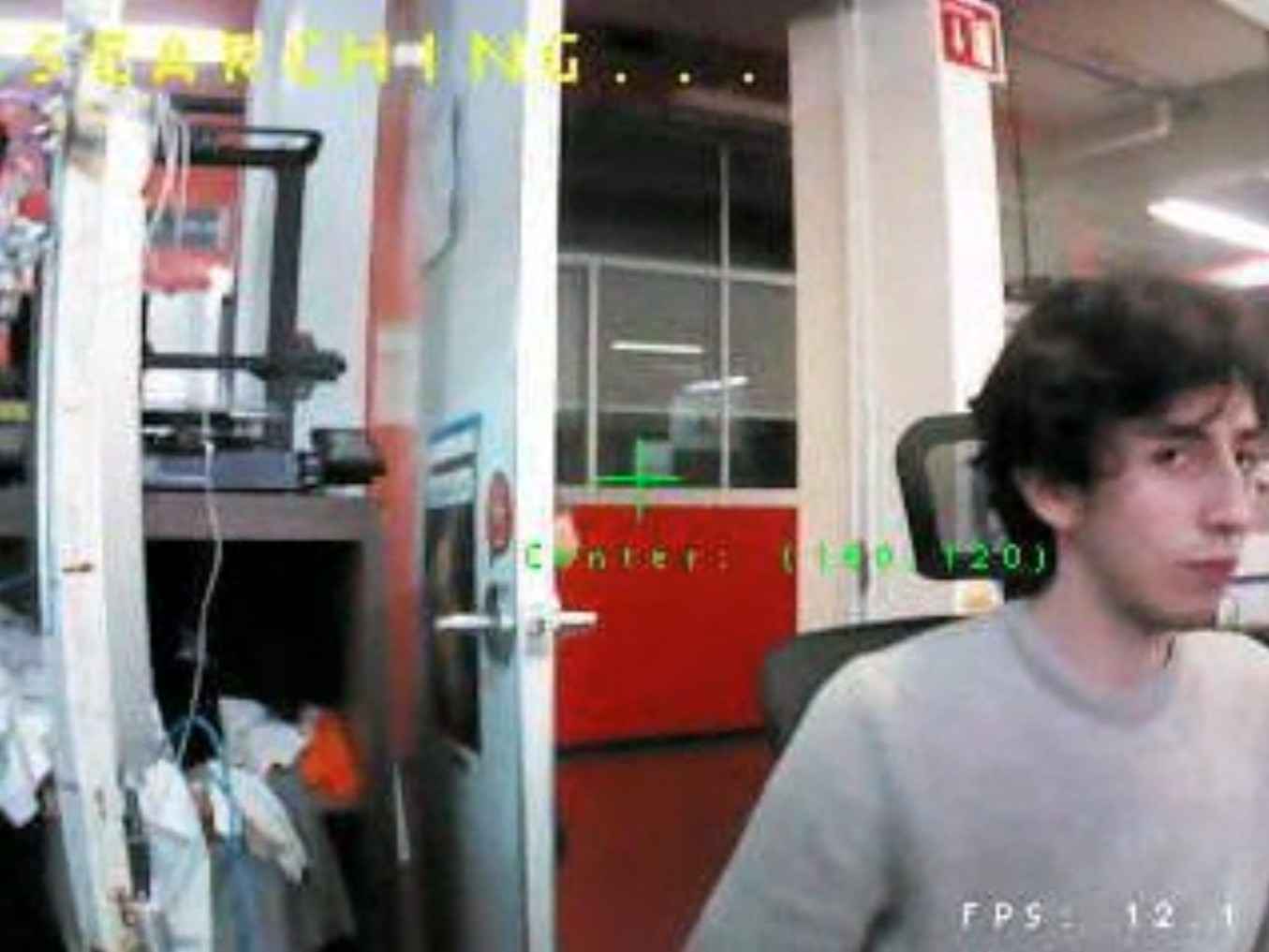
img.draw_string(5, 5, "SEARCHING...", color=(255, 255, 0), scale=2)
If no target is detected for more than 700 ms, the system enters search mode, commanding the robot to resume patrolling or idle posture.
12. FPS Monitoring
img.draw_string(img.width() - 80, img.height() - 15, f"FPS: {clock.fps():.1f}", color=(255, 255, 255), scale=1)
The system overlays the current frame rate at the bottom-right corner, aiding in performance monitoring.
6.2. XIAO RP2040 Programming
The XIAO RP2040 is the brain of the Observer Arm. It receives tracking data from the OpenMV H7 camera via UART and controls the system's actuators, two servo motors and a stepper motor, based on that data. It also features a patrol mode that engages when no target is detected.
	#include

#define SERVO1_PIN D9
#define SERVO2_PIN D10
#define DIR_PIN D3
#define STEP_PIN D4
#define LED_PIN D8

Servo servo1, servo2;

int angle1 = 30, target1 = 30;
int angle2 = 170, target2 = 170;
bool personDetected = false;

const int centerX = 160;
const int centerY = 120;

long lastStepTime = 0;
unsigned int stepInterval = 300;
unsigned int baseStepInterval = 300;
unsigned int currentStepInterval = 300;
int stepQueue = 0;
int totalSteps = 0;
int stepsExecuted = 0;
bool stepDir = true;

const int ACCEL_STEPS = 10;
const float ACCEL_FACTOR = 3.0;

int stepperPosition = 0;
const int patrolRange = 300;
bool patrolDir = true;
unsigned long lastPatrolTime = 0;
const unsigned long patrolDelay = 500;

unsigned long lastUpdate = 0;

bool commandProcessing = false;
String currentCommand = "";
unsigned long commandStartTime = 0;
const unsigned long MAX_PROCESSING_TIME = 2000;

void setup() {
  Serial1.begin(115200);
  pinMode(DIR_PIN, OUTPUT);
  pinMode(STEP_PIN, OUTPUT);
  pinMode(LED_PIN, OUTPUT);

  servo1.attach(SERVO1_PIN);
  servo2.attach(SERVO2_PIN);
  servo1.write(angle1);
  servo2.write(angle2);
}

void calculateStepInterval() {
  if (totalSteps <= ACCEL_STEPS * 2) {
    currentStepInterval = baseStepInterval;
    return;
  }
  if (stepsExecuted < ACCEL_STEPS) {
    float progress = (float)stepsExecuted / ACCEL_STEPS;
    currentStepInterval = baseStepInterval + (baseStepInterval * (ACCEL_FACTOR - 1.0) * (1.0 - progress));
  } else if (stepsExecuted >= (totalSteps - ACCEL_STEPS)) {
    int stepsFromEnd = totalSteps - stepsExecuted;
    float progress = (float)stepsFromEnd / ACCEL_STEPS;
    currentStepInterval = baseStepInterval + (baseStepInterval * (ACCEL_FACTOR - 1.0) * (1.0 - progress));
  } else {
    currentStepInterval = baseStepInterval;
  }
}

void sendACK() {
  Serial1.println("OK");
}

void sendNACK() {
  Serial1.println("NACK");
}

bool processCommand(String cmd) {
  if (cmd.startsWith("TRACK:")) {
    digitalWrite(LED_PIN, HIGH);
    personDetected = true;

    int p1 = cmd.indexOf(':');
    int p2 = cmd.indexOf(':', p1 + 1);
    int p3 = cmd.indexOf(':', p2 + 1);

    if (p1 == -1 || p2 == -1 || p3 == -1) return false;

    int x = cmd.substring(p1 + 1, p2).toInt();
    int y = cmd.substring(p2 + 1, p3).toInt();

    int dx = x - centerX;
    if (abs(dx) > 5) {
      stepDir = (dx > 0);
      int steps = map(abs(dx), 0, 160, 0, 50);
      stepQueue = min(steps, 50);
      totalSteps = stepQueue;
      stepsExecuted = 0;
      baseStepInterval = map(abs(dx), 0, 160, 900, 200);
      currentStepInterval = baseStepInterval * ACCEL_FACTOR;
    }

    int desired = map(y, 0, 240, 0, 45);
    target1 = constrain(desired, 0, 45);
    target2 = 140;
    return true;
  }
  else if (cmd == "NO_PERSON") {
    digitalWrite(LED_PIN, LOW);
    personDetected = false;
    target2 = 170;
    return true;
  }
  return false;
}

bool isMovementComplete() {
  return (stepQueue == 0) &&
         (abs(angle1 - target1) <= 1) &&
         (abs(angle2 - target2) <= 1);
}

void loop() {
  if (Serial1.available() && !commandProcessing) {
    String cmd = Serial1.readStringUntil('\n');
    cmd.trim();
    if (cmd.length() > 0) {
      currentCommand = cmd;
      commandProcessing = true;
      commandStartTime = millis();
      if (!processCommand(cmd)) {
        sendNACK();
        commandProcessing = false;
      }
    }
  }

  if (stepQueue > 0 && micros() - lastStepTime > currentStepInterval) {
    digitalWrite(DIR_PIN, stepDir);
    digitalWrite(STEP_PIN, HIGH);
    delayMicroseconds(180);
    digitalWrite(STEP_PIN, LOW);
    lastStepTime = micros();
    stepQueue--;
    stepsExecuted++;
    stepperPosition += (stepDir ? 1 : -1);
    calculateStepInterval();
  }

  if (millis() - lastUpdate > 10) {
    lastUpdate = millis();
    if (abs(angle1 - target1) > 0) {
      angle1 += (target1 > angle1) ? 1 : -1;
      servo1.write(angle1);
    }
    if (abs(angle2 - target2) > 0) {
      angle2 += (target2 > angle2) ? 1 : -1;
      servo2.write(angle2);
    }
  }

  if (commandProcessing) {
    if (isMovementComplete()) {
      sendACK();
      commandProcessing = false;
    } else if (millis() - commandStartTime > MAX_PROCESSING_TIME) {
      sendNACK();
      commandProcessing = false;
    }
  }

  if (!personDetected && !commandProcessing && stepQueue == 0 && millis() - lastPatrolTime > patrolDelay) {
    if (stepperPosition >= patrolRange) patrolDir = false;
    else if (stepperPosition <= -patrolRange) patrolDir = true;

    stepDir = patrolDir;
    stepQueue = 20;
    totalSteps = stepQueue;
    stepsExecuted = 0;
    baseStepInterval = 900;
    currentStepInterval = baseStepInterval * ACCEL_FACTOR;
    lastPatrolTime = millis();
  }
}
1. Pin Definitions and Variable Initialization
#include <Servo.h>

#define SERVO1_PIN D9
#define SERVO2_PIN D10
#define DIR_PIN D3
#define STEP_PIN D4
#define LED_PIN D8

Servo servo1, servo2;

int angle1 = 30, target1 = 30;
int angle2 = 170, target2 = 170;
bool personDetected = false;
This initializes the hardware setup. The servo pins control the height and extension of the arm, the stepper pins handle base rotation, and an onboard LED indicates detection status.
2. Stepper Motor Variables and Motion Parameters
long lastStepTime = 0;
unsigned int stepInterval = 300;
unsigned int baseStepInterval = 300;
unsigned int currentStepInterval = 300;
int stepQueue = 0;
int totalSteps = 0;
int stepsExecuted = 0;
bool stepDir = true;

const int ACCEL_STEPS = 10;
const float ACCEL_FACTOR = 3.0;
These variables manage the stepper motor's speed and acceleration profile. Acceleration is simulated by gradually decreasing the interval between steps.
3. Patrol Mode Variables
int stepperPosition = 0;
const int patrolRange = 300;
bool patrolDir = true;
unsigned long lastPatrolTime = 0;
const unsigned long patrolDelay = 500;
When no person is detected, the arm enters a patrol routine, rotating left and right within a defined range of 300 steps from the center position.
4. Command Buffer and Setup Function
unsigned long lastUpdate = 0;
bool commandProcessing = false;
String currentCommand = "";
unsigned long commandStartTime = 0;
const unsigned long MAX_PROCESSING_TIME = 2000;

void setup() {
  Serial1.begin(115200);
  pinMode(DIR_PIN, OUTPUT);
  pinMode(STEP_PIN, OUTPUT);
  pinMode(LED_PIN, OUTPUT);

  servo1.attach(SERVO1_PIN);
  servo2.attach(SERVO2_PIN);
  servo1.write(angle1);
  servo2.write(angle2);
}
The setup function initializes communication, configures I/O pins, and sets the default servo angles.
5. Acceleration Calculation Function
void calculateStepInterval() {
  if (totalSteps <= ACCEL_STEPS * 2) {
    currentStepInterval = baseStepInterval;
    return;
  }
  if (stepsExecuted < ACCEL_STEPS) {
    float progress = (float)stepsExecuted / ACCEL_STEPS;
    currentStepInterval = baseStepInterval + (baseStepInterval * (ACCEL_FACTOR - 1.0) * (1.0 - progress));
  } else if (stepsExecuted >= (totalSteps - ACCEL_STEPS)) {
    int stepsFromEnd = totalSteps - stepsExecuted;
    float progress = (float)stepsFromEnd / ACCEL_STEPS;
    currentStepInterval = baseStepInterval + (baseStepInterval * (ACCEL_FACTOR - 1.0) * (1.0 - progress));
  } else {
    currentStepInterval = baseStepInterval;
  }
}
This function simulates motor acceleration and deceleration, smoothing movement by adjusting the delay between pulses.
6. Communication Response Handlers
void sendACK() {
  Serial1.println("OK");
}

void sendNACK() {
  Serial1.println("NACK");
}
These functions send responses back to the OpenMV camera, confirming whether a command was successfully executed or not.
7. Command Processing Function
bool processCommand(String cmd) {
  if (cmd.startsWith("TRACK:")) {
    digitalWrite(LED_PIN, HIGH);
    personDetected = true;

    int p1 = cmd.indexOf(':');
    int p2 = cmd.indexOf(':', p1 + 1);
    int p3 = cmd.indexOf(':', p2 + 1);

    if (p1 == -1 || p2 == -1 || p3 == -1) return false;

    int x = cmd.substring(p1 + 1, p2).toInt();
    int y = cmd.substring(p2 + 1, p3).toInt();

    int dx = x - centerX;
    if (abs(dx) > 5) {
      stepDir = (dx > 0);
      int steps = map(abs(dx), 0, 160, 0, 50);
      stepQueue = min(steps, 50);
      totalSteps = stepQueue;
      stepsExecuted = 0;
      baseStepInterval = map(abs(dx), 0, 160, 900, 200);
      currentStepInterval = baseStepInterval * ACCEL_FACTOR;
    }

    int desired = map(y, 0, 240, 0, 45);
    target1 = constrain(desired, 0, 45);
    target2 = 140;
    return true;
  }
  else if (cmd == "NO_PERSON") {
    digitalWrite(LED_PIN, LOW);
    personDetected = false;
    target2 = 170;
    return true;
  }
  return false;
}
The `TRACK:` command parses the X and Y coordinates, calculates how many steps the stepper should move, and sets the servo positions. If no person is detected, the `NO_PERSON` command resets the arm.
8. Movement Completion Check
bool isMovementComplete() {
  return (stepQueue == 0) &&
         (abs(angle1 - target1) <= 1) &&
         (abs(angle2 - target2) <= 1);
}
Used to determine whether all movements (stepper and servos) have finished before sending an ACK.
9. Main Loop: Command Handling
void loop() {
  if (Serial1.available() && !commandProcessing) {
    String cmd = Serial1.readStringUntil('\n');
    cmd.trim();
    if (cmd.length() > 0) {
      currentCommand = cmd;
      commandProcessing = true;
      commandStartTime = millis();
      if (!processCommand(cmd)) {
        sendNACK();
        commandProcessing = false;
      }
    }
  }
This section receives serial commands from the OpenMV camera and triggers processing logic if available.
10. Stepper Pulse Control
  if (stepQueue > 0 && micros() - lastStepTime > currentStepInterval) {
    digitalWrite(DIR_PIN, stepDir);
    digitalWrite(STEP_PIN, HIGH);
    delayMicroseconds(180);
    digitalWrite(STEP_PIN, LOW);
    lastStepTime = micros();
    stepQueue--;
    stepsExecuted++;
    stepperPosition += (stepDir ? 1 : -1);
    calculateStepInterval();
  }
This generates pulses for the stepper motor, updating position and adjusting timing dynamically based on acceleration.
11. Servo Movement Smoothing
  if (millis() - lastUpdate > 10) {
    lastUpdate = millis();
    if (abs(angle1 - target1) > 0) {
      angle1 += (target1 > angle1) ? 1 : -1;
      servo1.write(angle1);
    }
    if (abs(angle2 - target2) > 0) {
      angle2 += (target2 > angle2) ? 1 : -1;
      servo2.write(angle2);
    }
  }
Gradually updates servo angles to ensure smooth motion instead of abrupt changes.
12. ACK/NACK Sending Based on Completion
  if (commandProcessing) {
    if (isMovementComplete()) {
      sendACK();
      commandProcessing = false;
    } else if (millis() - commandStartTime > MAX_PROCESSING_TIME) {
      sendNACK();
      commandProcessing = false;
    }
  }
Evaluates whether the current movement is complete. If successful, sends an `OK`; if it times out, sends a `NACK`.
13. Patrol Behavior When Idle
  if (!personDetected && !commandProcessing && stepQueue == 0 && millis() - lastPatrolTime > patrolDelay) {
    if (stepperPosition >= patrolRange) patrolDir = false;
    else if (stepperPosition <= -patrolRange) patrolDir = true;

    stepDir = patrolDir;
    stepQueue = 20;
    totalSteps = stepQueue;
    stepsExecuted = 0;
    baseStepInterval = 900;
    currentStepInterval = baseStepInterval * ACCEL_FACTOR;
    lastPatrolTime = millis();
  }
}
In the absence of detection and commands, the robot enters patrol mode. It sweeps back and forth across a 600-step arc to actively search for targets, maintaining engagement.
6.3. Code Interaction
Together, the OpenMV H7 and the XIAO RP2040 work in seamless coordination to achieve real-time target tracking. The OpenMV H7 handles the heavy lifting of computer vision by using a pre-trained FOMO face detection model to identify and localize human targets within the frame. Once a person is detected, the camera calculates their coordinates and the bounding box area, then formats and sends this data via UART to the XIAO. The XIAO RP2040 interprets this information and translates it into smooth mechanical movements by actuating the servos and the stepper motor. A custom-designed ACK/NACK communication protocol ensures synchronized behavior and minimizes delays or errors. If no person is detected, the camera sends a "NO_PERSON" command, prompting the XIAO to retract the arm and engage a patrol routine, sweeping back and forth until a target reappears. This tightly integrated system creates an intelligent robotic arm capable of autonomously detecting, tracking, and responding to human presence in its environment.
I'd like to take the opportunity to thank my peer Erwin for his assistance in the programming process, his experience and insights in computer vision and communications were incredibly helpful.
6.4 Interface
One of the most helpful tools during the development of the Observer Arm was the integration of a live graphical interface on the OpenMV H7 camera's video feed. This overlay displays real-time information about the detected object and tracking process, making the system more interactive.
The interface is composed entirely of annotations and visual guides rendered using the image module on the OpenMV board. These visual elements serve to convey both the state of the system and precise detection data. Below is a breakdown of each annotation and its purpose:
                img.draw_rectangle((x, y, w, h), color=(255, 0, 0), thickness=2)
                img.draw_circle((center_x, center_y, 8), color=(255, 0, 0), thickness=2)
                img.draw_string(x, y - 12, f"({center_x},{center_y})", color=(255, 255, 0), scale=1)
                img.draw_string(x, y + h + 2, f"Conf: {score:.2f}", color=(255, 255, 0), scale=1)
                img.draw_string(x, y + h + 14, f"Area: {area}", color=(255, 255, 0), scale=1)
                dx = center_x - centerX
                dy = center_y - centerY
                img.draw_string(x, y + h + 26, f"Offset: ({dx:+d},{dy:+d})", color=(0, 255, 255), scale=1)
                img.draw_line(centerX, centerY, center_x, center_y, color=(255, 0, 255), thickness=1)
                img.draw_string(5, 5, "TARGET LOCKED", color=(0, 255, 0), scale=2)

                send_command_and_wait_ack(f"TRACK:{center_x}:{center_y}:{area}")
                person_detected = True
                last_seen = pyb.millis()
                break  # only one detection per loop
Detection Annotations and Target Tracking
img.draw_rectangle((x, y, w, h), color=(255, 0, 0), thickness=2)Draws a bounding box around the detected target in bright red. This rectangle encloses the area identified by the FOMO face detection model and is the primary visual cue for object tracking.
img.draw_circle((center_x, center_y, 8), color=(255, 0, 0), thickness=2)Places a circle at the center of the bounding box. This visually marks the calculated central point of the detected object, which is the actual reference point for tracking movements.
img.draw_string(x, y - 12, f"({center_x},{center_y})", color=(255, 255, 0), scale=1)Displays the coordinates of the target center above the bounding box, providing a precise reference to where the camera believes the object is in the 2D frame.
img.draw_string(x, y + h + 2, f"Conf: {score:.2f}", color=(255, 255, 0), scale=1)Shows the confidence score of the detection just below the bounding box. This value, ranging from 0.00 to 1.00, indicates how certain the model is about the detection.
img.draw_string(x, y + h + 14, f"Area: {area}", color=(255, 255, 0), scale=1)Displays the area in pixels of the detected bounding box. This measurement is useful for estimating relative distance to the camera.
dx = center_x - centerX
dy = center_y - centerY
img.draw_string(x, y + h + 26, f"Offset: ({dx:+d},{dy:+d})", color=(0, 255, 255), scale=1)
Calculates and displays the offset from the image center. This information is critical to the control system, as it informs the microcontroller how far and in what direction to move the servos and stepper motor to re-center the target.
img.draw_line(centerX, centerY, center_x, center_y, color=(255, 0, 255), thickness=1)Draws a vector line from the frame center to the target, making it visually easy to grasp the direction and magnitude of deviation from the ideal center.
img.draw_string(5, 5, "TARGET LOCKED", color=(0, 255, 0), scale=2)Indicates the status of tracking in large green letters at the top-left corner when a target is successfully detected and tracked.
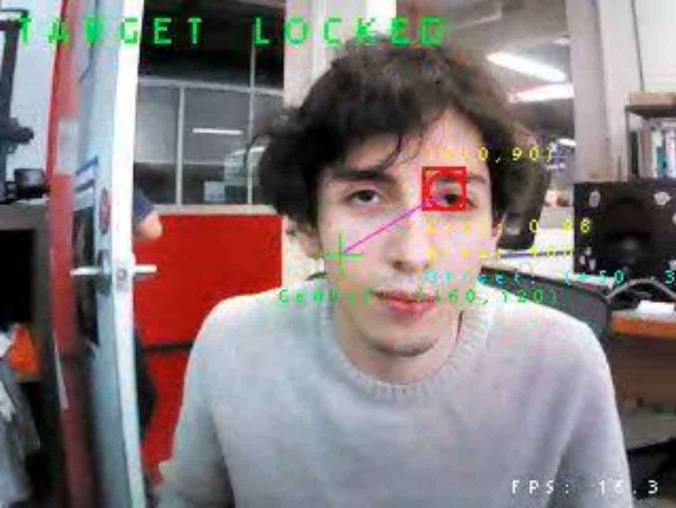
This interface transforms the camera from a "black box" into a visual debugging and feedback tool, significantly accelerating the development process. It also serves as an effective demonstration aid, as viewers can clearly understand what the robot sees, how it reacts, and how well it is performing its task.
7. System Integration
System integration was one of the most rewarding phases of the project. Once all the physical components were fabricated and the electronics were tested individually, the complete assembly of the robotic arm came together surprisingly smoothly. The mechanical components were primarily joined through carefully designed pressure fits, which proved even more reliable after painting. The additional layer of acrylic enamel provided just enough friction to eliminate the need for screws in most joints, only the arm assembly, the NEMA 17 stepper motor, and the axial rods required fastening. The arm, in particular, had to be screwed together due to the internal routing of cables that introduced outward pressure during motion.
From the design phase, cable management was thoughtfully taken into consideration for both functionality and aesthetics. The UART and USB cables from the OpenMV H7 camera, located at the arm's end effector, run internally through the two arm segments. A protective mesh sleeve keeps them secured and tidy until the UART cables connect with the main PCB, and the USB cable goes to the user's PC. Power cables for the servos and stepper motor were also routed using this mesh system, color-coded and bundled into the mesh leading directly to the external power supply. Where cable extensions were needed, male-female Dupont connectors were reinforced using heat-shrink tubing to prevent disconnections during motion.
The electronics were cleanly integrated into the structure. Most modules, including the camera, servo mounts, and the V3 PCB, were inserted into dedicated press-fit slots. Only the NEMA 17 motor was screwed into position using a cap secured beneath the axial bearing. One hardware limitation remained, since the arm does not include a slip ring, it cannot rotate endlessly. After several full rotations, the cables begin to twist, eventually risking disconnection. This is one of the critical upgrades planned for future iterations.
With the mechanical and electrical systems assembled, the programming phase began. The OpenMV H7 camera was connected to the PC for real-time deployment and monitoring. (Note: full standalone operation would require the addition of a battery and SD card, which remains a viable upgrade.) The XIAO RP2040 was flashed with the control code, enabling UART-based communication with the camera.
Testing was an iterative process, beginning with basic servo control and stepper responsiveness. Gradually, code was refined to balance smoothness and stability of motion, especially under real-time visual tracking. A major breakthrough came when my Fab Academy peer, Erwin, introduced the idea of implementing an ACK/NACK protocol to manage communication integrity between the microcontroller and the camera. This significantly improved synchronization and reduced erratic behavior.
The final result is a fully integrated robotic vision system that tracks human presence with surprising precision and mechanical elegance. It smoothly interprets visual data, responds to positional changes, and remains open to future upgrades. For a project born out of a need for improved surveillance, the performance far exceeded my initial expectations.
8. Results
The development and final integration of the Observer Arm yielded positive and insightful outcomes. The prototype successfully accomplished its intended goal: to detect and follow a human target using a computer vision system, with coordinated mechanical response across three axes, vertical articulation, extension, and rotational positioning. The result is a system that can autonomously align its motion based on real-time positional data, using modular components and an accessible fabrication workflow.
Throughout the project, several fundamental questions were answered. Chief among them: Can an open-source, low-cost robotic system be built to autonomously track a target using vision input? Can such a system be made modular, replicable, and extensible for future use by others? The outcome affirms these possibilities. The Observer Arm demonstrates that, with the right design principles and iterative design, a cohesive and reliable human-tracking platform can be achieved using accessible technologies.
What worked exceptionally well was the mechanical design. The implementation of the perfect parallelogram mechanism allowed the end effector to retain its orientation across multiple movements, while the architecture of the system proved ideal for adjustments and upgrades. Communication between the OpenMV H7 and the XIAO RP2040 microcontroller also became very smooth after implementing the ACK/NACK protocol, ensuring synchronization and command reliability. The vision system provided consistent detection, and the real-time responses were functionally accurate.
What did not work as initially envisioned was the stepper motor control. While the geared NEMA 17 was capable of providing adequate torque, achieving the same smoothness and refined motion profile seen in commercial or CNC-grade systems proved challenging. This was primarily a limitation of programming experience and real-time motor control strategies. Despite attempts at acceleration profiles and patrol mode logic, the motion of the stepper remains an area where noticeable improvements can be made in future iterations.
The system was evaluated by directly testing its capacity to perform its goal: to detect, lock on, and track a human subject using vision input, adjusting the position of the robotic arm accordingly. This involved confirming camera responsiveness, verifying the mechanical integrity and coordination of the three motion axes, and ensuring that communications were stable. The robot was tested numerous times to ensure its repeatability. Overall, it succeeded in maintaining tracking behavior and providing a responsive interaction model. Smoother motion, particularly in rotational tracking, remains a goal for future development.
The implications of the Observer Arm are promising. It serves not only as a working solution for a specific surveillance and tracking application but also as a platform for further research, education, or personalization. Its open and modular nature invites users to build upon it, adapt it for other end effectors or tasks, or integrate more advanced features such as wireless communication, slip rings for continuous rotation, or other types of motors for refined control.
In summary, the Observer Arm project stands as a strong proof of concept, affirming that computer vision, embedded systems, and digitally fabricated mechanics can come together to produce intelligent, purposeful robotics, even more so within the resourcefulness of a Fab Lab environment.
9. Final Thoughts and Comments
Bringing the Observer Arm to life was not only a technical challenge, but also a profound learning journey that highlighted the power of multidisciplinary knowledge. Each component of this system, from its precision mechanical structure to its electronics, embedded code, and even its final aesthetic — was only made possible through the diverse set of skills developed throughout the Fab Academy. The convergence of computer-aided design, digital fabrication, embedded programming, and systems integration proved essential for transforming a conceptual sketch into a working, responsive machine.
Beyond the technical, this experience underscored the importance of collaboration, mentorship, and community. I'd like to sincerely thank my local instructor, fellow students, global evaluators, and the broader Fab Academy network for their guidance and support. This project stands not only as a result of individual effort, but as a testament to the shared spirit of learning and invention that defines Fab Academy.
Additional thanks to photographer Cristina Bolaños for her assistance and artist KoruSe for allowing me to use his music in the presentation video.
In the end, the Observer Arm is more than a surveillance prototype, to me it serves as a representation of what can be achieved when creativity is paired with the right tools and support. I look forward to building on this foundation and to continuing this journey of making, learning, and sharing.
Files
Observer Arm © 2025 by José Carlos Matanzo Pérez is licensed under CC BY 4.0