10. Output Devices
Summary
For this week's assignment we had to add an output device to a microcontroller board of our design, and program it to do something. For our group assignment, we measured the power consumption of multiple output devices.
1. Introduction to Output Devices
Output devices are electronic components that take signals from a microcontroller and transform them into physical actions.
As I mentioned in the previous week , our systems usually follow the same procedure, starting with the inputs, then the processing of the input data through code, and finally the output. These outputs can be motion, sound, light, heat, or communication signals.
2. Types of Output Devices
Actuators
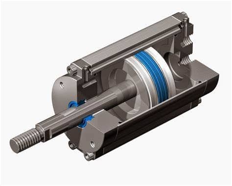
Actuators convert electrical energy into mechanical motion.
- DC Motors - Provide continuous rotation at variable speed.
- Stepper Motors - Rotate in precise steps for accurate positioning.
- Servo Motors - Rotate to a specific angle using PWM signals.
- Linear Actuators - Convert electrical input into linear motion.
- Hydraulic/Pneumatic Actuators - Use the pressure of a fluid to generate motion.
Light Emitter Devices
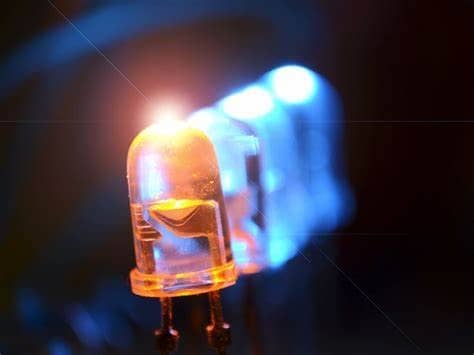
These devices provide visual outputs by emitting or displaying light.
- LEDs - Produce light in different colors.
- 7 Segment Displays - Show numbers and letters using LED segments.
- OLED & LCD Displays - Display images, text, or animations.
Sound Emitter Devices
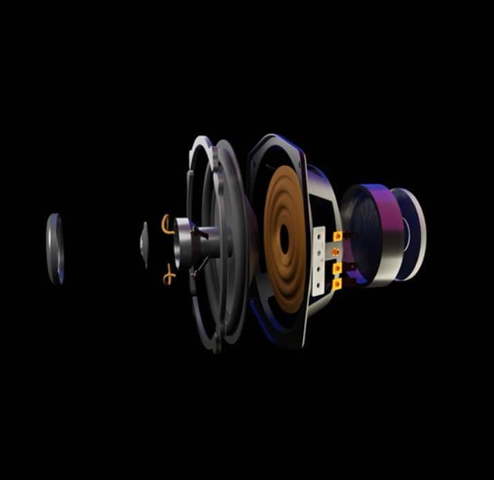
These devices convert electrical signals into sound waves.
- Buzzers - Produce beeps, alarms, or tones.
- Speakers - Convert signals into audio playback.
- Ultrasonic Transducers - Emit high frequency sound waves for sensing.
Energy Conversion Devices
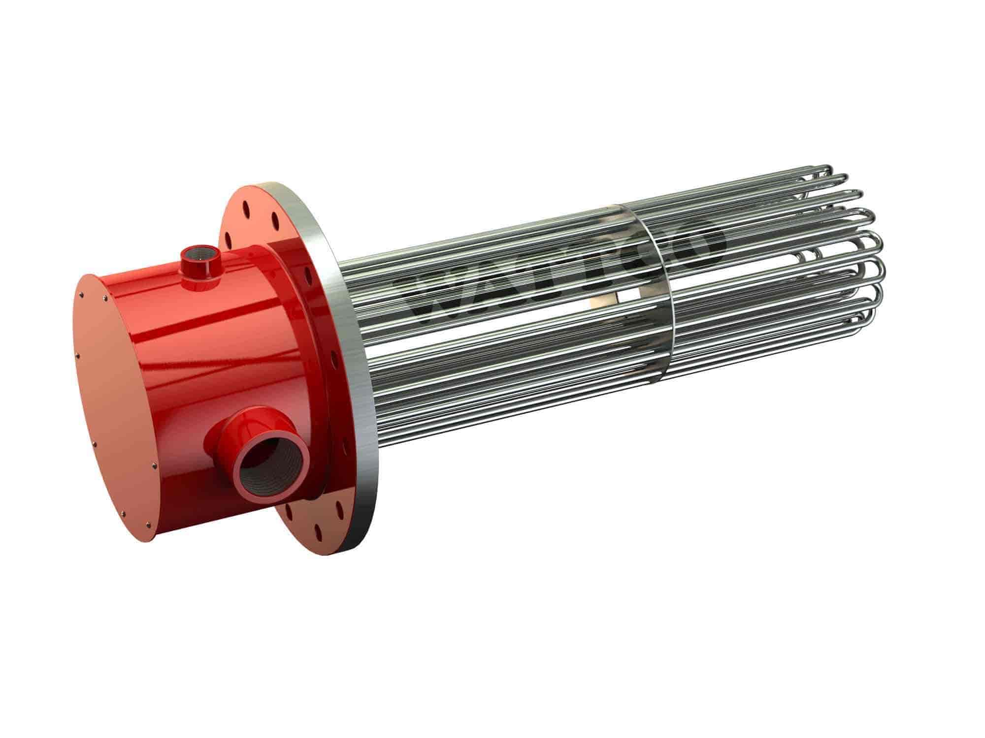
These devices generate heat or convert electrical energy into another form.
- Heating Elements - Convert electricity into heat.
- Peltier Modules - Can be used for cooling or heating.
Communication Devices
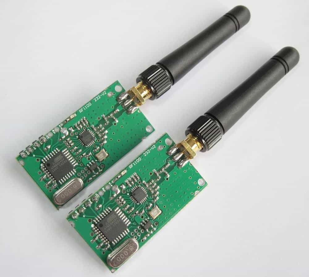
These devices transmit data signals or provide wireless connectivity.
- RF Modules - Send wireless radio signals.
- Bluetooth Modules - Enable short range wireless communication.
3. Actuators; Servo and Stepper Motors
The output devices that I worked with this week were actuators, specifically servo motors and stepper motors.
As I mentioned, actuators are devices that convert electrical energy into mechanical motion. Among them, servo motors and stepper motors are widely used for precise motion control in robotics, automation, and industrial applications.
3.1 Servo Motors
A servo motor is a closed-loop actuator that moves to a specific position based on a control signal known as Pulse-Width Modulation or PWM signal. Unlike DC motors, which spin continuously, servos rotate within a set range of typically 0° to 180°.
Components
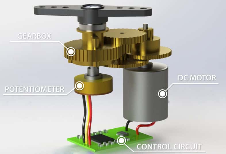
- Motor - Provides rotational movement.
- Gearbox - Increases torque and reduces speed.
- Shaft - Outputs the rotational motion.
- Potentiometer - Measures the shaft position.
- Control Circuit - Adjusts the motor's position based on the input signal.
How they work
Servos receive a PWM signal with a fixed frequency of a 50Hz / 20ms period.The pulse width determines the angle:
- 1ms pulse - 0° position
- 1.5ms pulse - 90° position
- 2ms pulse - 180° position
3.2 Stepper Motors
A stepper motor is a brushless DC motor that moves in discrete steps instead of continuous rotation. It is an open loop actuator, meaning it moves a fixed amount per pulse but doesn't inherently know its exact position unless encoders are used.
Components
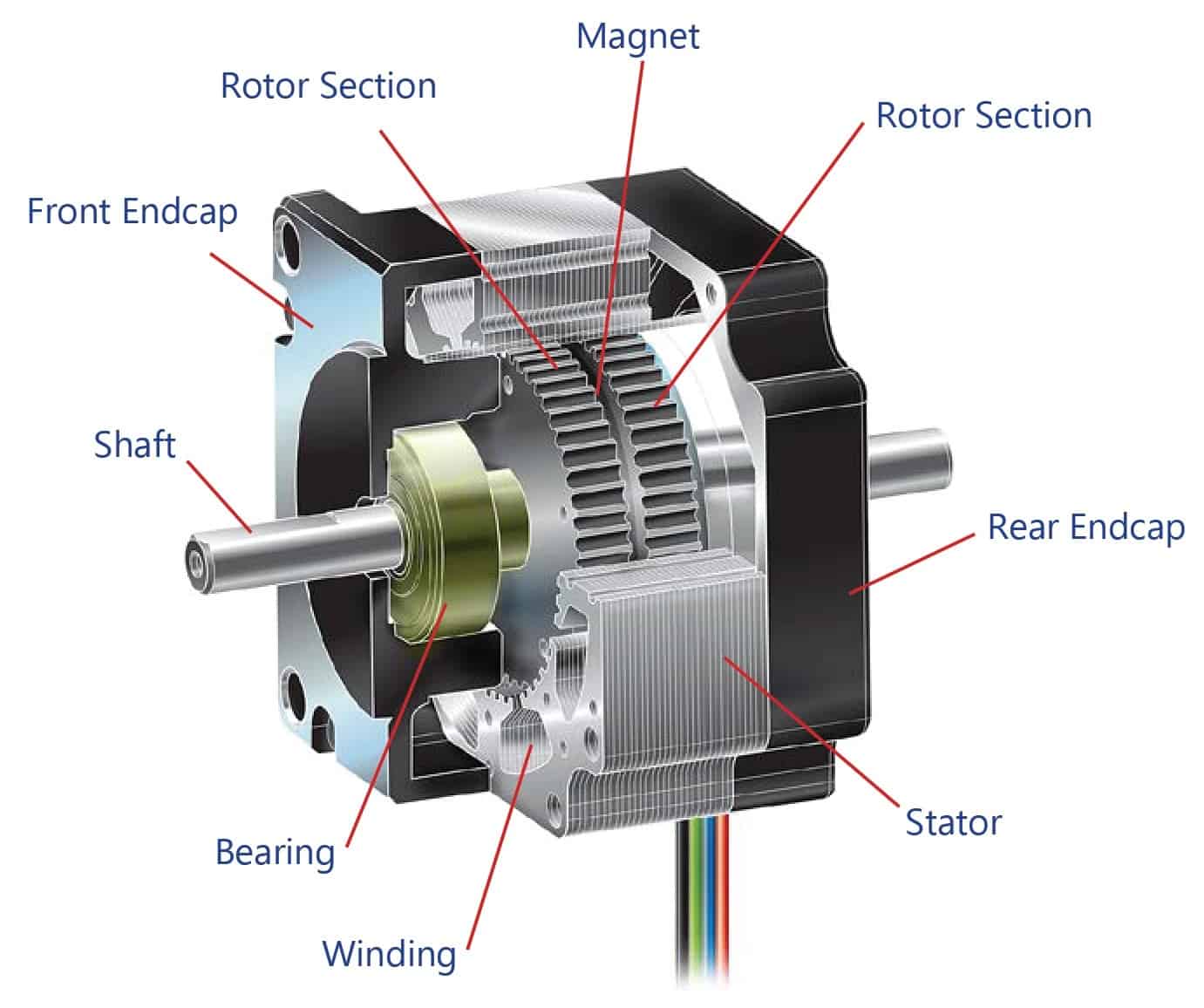
- Coils - Multiple electromagnetic coils that are energized in a sequence, creating a rotating magnetic field that moves the rotor step by step.
- Rotor - The rotor is the rotating part of the motor that follows the electromagnetic field generated by the coils.
- Bearings - Support the rotor and allow smooth rotation with minimal friction.
- Shaft - Outputs the rotational motion.
- Motor Phases- The motor's coils are grouped into phases that determine movement precision. A Bipolar Stepper has 2 phases, controlled through 4 wires, and require an H-Bridge driver like the A4988.
H-Bridge Driver
An H-Bridge is a circuit used to control the direction and speed of a DC motor or stepper motor by switching the polarity of voltage applied to it.It consists of four switches, which are transistors or MOSFETs arranged in an H-shape circuit. By opening and closing specific switches, the circuit allows current to flow in different directions, reversing the motor's rotation.
The driver that I used this week is an A4988, which is an integrated bipolar stepper motor driver that allows microcontrollers to control stepper motors with high precision.
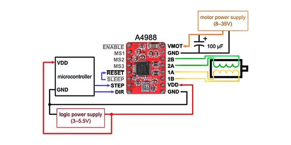
The A4988 follows a simple STEP/DIR control system:
- DIR Pin - HIGH (Clockwise), LOW (Counterclockwise).
- STEP Pin - Each pulse moves the motor one step forward.
- MS1, MS2, MS3 - Microstepping pins that control the precision of movement.
How they work
The A4988 stepper driver requires two separate power inputs:- Logic Power (VDD) - Supplies 3.3V or 5V for the driver's control circuit.
- Motor Power (VMOT) - Supplies 8V-35V for the stepper motor.
After connecting:
- STEP and DIR pins to the microcontroller for control.
- RESET and SLEEP pins together to keep the driver active.
- Motor coils to the A1, A2, B1, B2 output terminals.
If we want smoother movements, we can enable the microstepping pins and configure the steps through code.
4. My Motor Control System
This week I controlled two DS3218 servo motors and a Nema 17 stepper motor with a PCB of my own design, which we will call V2.
This PCB is an upgraded version of the PCB that I manufactured during week 08, which we will call V1. It follows the same design principles, but I optimized the layout of the components and corrected some major mistakes.
4.1 Schematic Design
The schematic is very similar to V1's, the main difference is the general layout and the placement of capacitors near the power pins of the motors, and near the DIR and STEP pins of the A4988. I used 100 nF ceramic capacitors for the STEP, DIR and servo power pins, and a 220uF electrolytic capacitor for the power lines of the stepper motor.
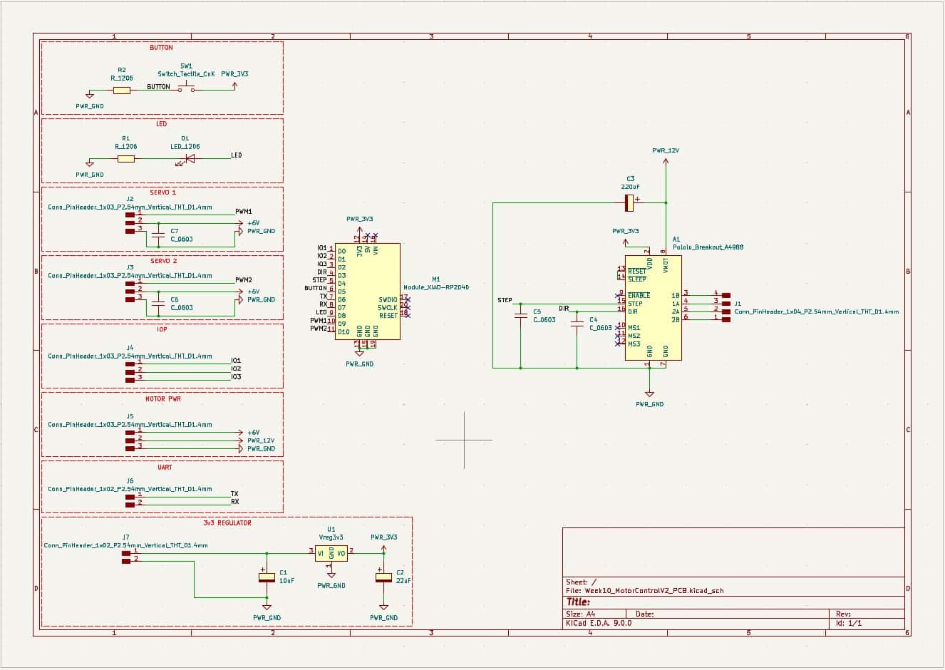
I corrected a major mistake regarding the VDD line of the A4988, which was previously part of the 5 V line shared with the servos, it now feeds directly from the XIAO's 3.3 V output.
The values of the components are the same as the ones in V1, but I added more capacitors for noise reduction and power stability. I used four 603 100 nF capacitors and one 220 uF electrolytic capacitor.
4.2 PCB Design
Now being more confident in my solderig skills, I tried to optimize the layout to make it more compact.
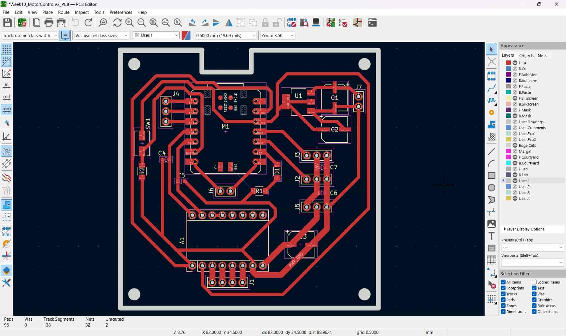
I corrected a major mistake present on V1's layout, first is the placement of the button, which was in the way of the Type-C cable, it is now located at the left of the XIAO. Since we only had smaller, 4 x 3 mm buttons available, I changed the footprint to generate accurate pads.
I also added a hole on the top of the edge cuts to fit the Type-C cable.
4.3 PCB Production
I followed the same process with the monoFab that I described in week 8's assignment. Starting by generating the SVGs, then the toolpaths on the mods CE webpage.
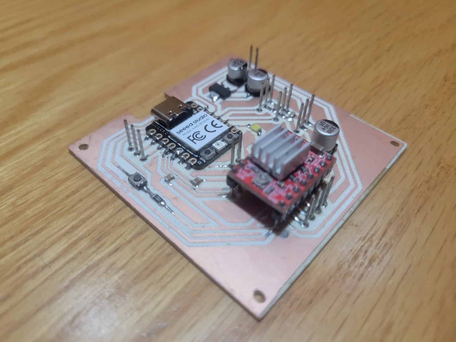
The carving process went smoothly, taking about an hour. I was using the leftovers from a friend's FR-4 board, which were slightly buckled, but not enough to affect the tracks by a significant amount.
After being done with the monoFab, I soldered the components, starting from the center and going outwards, it felt way easier than the first time, and I have to say, I'm much happier with the results.
4.4 Code
I used essentially the same as the second code in section 8 of week 08's assignment, only changing the pins to the corresponding ones in the new PCB.
#include <Servo.h>

// Pin Definitions
#define LED_PIN   D8
#define BUTTON_PIN D5
#define SERVO_1_PIN D10
#define SERVO_2_PIN D9
#define DIR_PIN  D3
#define STEP_PIN D4

// Servo Objects
Servo servo1;
Servo servo2;

void setup() {
    // Pin Modes
    pinMode(LED_PIN, OUTPUT);
    pinMode(BUTTON_PIN, INPUT);
    pinMode(DIR_PIN, OUTPUT);
    pinMode(STEP_PIN, OUTPUT);

    // Attach Servos
    servo1.attach(SERVO_1_PIN);
    servo2.attach(SERVO_2_PIN);

    // Initialize Serial Monitor
    Serial.begin(115200);
    Serial.println("System Ready. Use commands: S1 angle | S2 angle | M direction steps");
}

void loop() {
    // LED Control with Button
    if (digitalRead(BUTTON_PIN) == HIGH) {
        digitalWrite(LED_PIN, HIGH);
    } else {
        digitalWrite(LED_PIN, LOW);
    }

    // Check for Serial Commands
    if (Serial.available()) {
        String command = Serial.readStringUntil('\n');
        command.trim();

        // Servo 1 Command (e.g., "S1 90")
        if (command.startsWith("S1")) {
            int angle = command.substring(3).toInt();
            angle = constrain(angle, 0, 180); // Limit range
            servo1.write(angle);
            Serial.print("Servo 1 moved to ");
            Serial.print(angle);
            Serial.println(" degrees");
        }

        // Servo 2 Command (e.g., "S2 45")
        else if (command.startsWith("S2")) {
            int angle = command.substring(3).toInt();
            angle = constrain(angle, 0, 180);
            servo2.write(angle);
            Serial.print("Servo 2 moved to ");
            Serial.print(angle);
            Serial.println(" degrees");
        }

        // Stepper Motor Command (e.g., "M 1 200")
        else if (command.startsWith("M")) {
            int spaceIndex1 = command.indexOf(' ');
            int spaceIndex2 = command.lastIndexOf(' ');

            if (spaceIndex1 > 0 && spaceIndex2 > spaceIndex1) {
                int direction = command.substring(spaceIndex1 + 1, spaceIndex2).toInt();
                int steps = command.substring(spaceIndex2 + 1).toInt();

                digitalWrite(DIR_PIN, direction > 0 ? HIGH : LOW);
                Serial.print("Stepper moving ");
                Serial.print(direction > 0 ? "forward" : "backward");
                Serial.print(" for ");
                Serial.print(steps);
                Serial.println(" steps");

                for (int i = 0; i < steps; i++) {
                    digitalWrite(STEP_PIN, HIGH);
                    delayMicroseconds(500);
                    digitalWrite(STEP_PIN, LOW);
                    delayMicroseconds(500);
                }
            }
        }
    }
}
4.5 Connections
Now that we have the PCB and code ready, we can connect the motors and power supply.
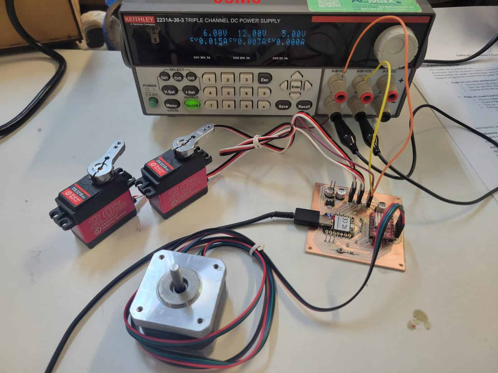
I arranged the pins to easily identify and connect the motors. Starting with the servos at the right of the PCB, these are connected on the first two sets of three pins from at the just bellow the 3.3 V regulator, the pin closest to the XIAO is the PWM pin, the middle is power and the right pin is ground.
The stepper motor is simply connected to the four pins below the A4988.
4.5.1 Power Supply
I used an external power supply to feed the motors, it is worth noting that the DS3218 servos that I used work within a voltage range of 4.8 to 6.8 V, the stepper motor works with 12 V. It is imperative that we keep these voltages in mind when setting up our power supply.
Once setting the correct voltages on two different channels, I set the current to 2 A max for the servos and 1 A for the stepper.
I connected the power supply to my motor power pins, located below the second servo motor's pins, the left pin is for the servos, the middle is for the stepper and the right pin is ground. I also connected the grounds of both channels on the power supply.
I tested each device to determine the current and power consumption of the system.
| Device | Condition | Current | Voltage | Power |
|---|---|---|---|---|
| DS3218 (each) | Idle | 0.008 A | 6 V | 0.048 W |
| DS3218 (each) | Max (no load) | 0.555 A | 6 V | 3.33 W |
| NEMA 17 | Idle | 0.14 A | 12 V | 1.68 W |
| NEMA 17 | Max (no load) | 0.18 A | 12 V | 2.16 W |
Total System Power
| Scenario | DS3218 (x2) | NEMA 17 | Total Power |
|---|---|---|---|
| All Idle | 0.096 W | 1.68 W | 1.776 W |
| All Max (No Load) | 6.66 W | 2.16 W | 8.82 W |
4.6 Testing
I connected my XIAO to my PC and turned on the power supply. Once ready, I opened the serial monitor on the Arduino IDE, set the baud rate to 115200 and began sending commands.
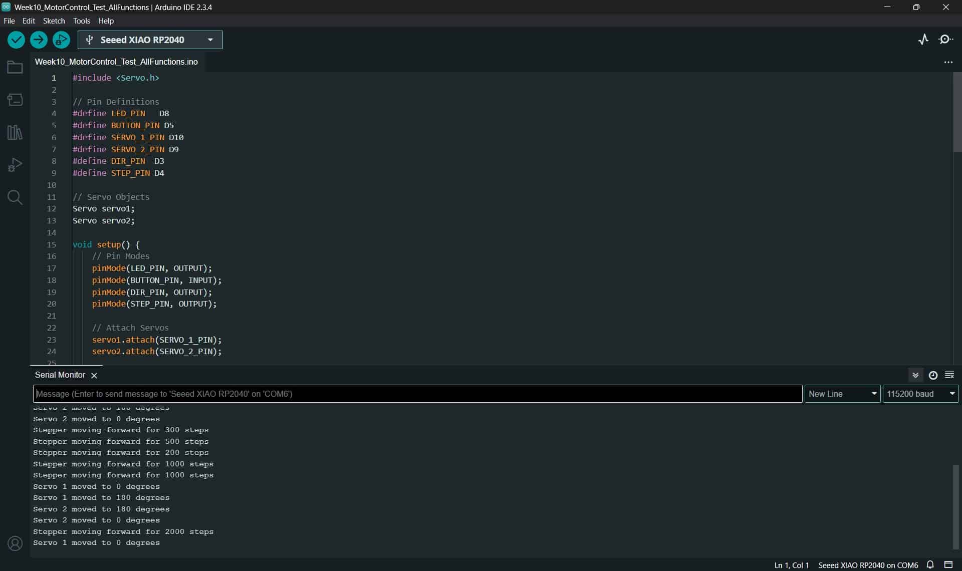
Everything worked flawlesly.
5. Comments and Recommendations
The most important comment this week is to carefully check the specified voltage and current that your components require, and take that into account when designing your PCB. Use the KiCad calculator to check your design parameters based on the current that you will be working with.
Maintain the power lines of your components completely separate, as I did with my 3.3 V logic, 6 V for servos and 12 V for stepper motor, the only point where they meet is the ground, which has to be completely unified for your circuit to work properly.
6. Learning Outcomes
This week I made an improved version of my previous PCB, which I used to control two separate servos and a stepper motor.
With the progress made this week, I'm very close to grapping up the electronics and programing aspects of my final project, now I have to focus on using the inputs from the OpenMV H7 camera to control my outputs, a challenge to be sure, but a welcome one.
