Final Project Development History
Initial Sketch
My first idea for a final project consists in a small robot arm that uses a camera and image recognition artificial inteligence to identify and physically track an objective.
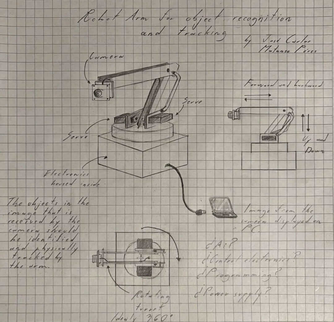
This project is intended to demostrate the capabilities of computer vision and serve as a guide on how to create a system based on it. Here is the first 3D model of the design, developed as part of my week 2 assignment:
I plan to use open source computer vision code, two servomotors for the movement of the joints and a stepper motor for the movement of the base.
I am still deciding what microcontroller to use, since I want to have enough processing power to have smooth tracking and movement.
Here are the components that I am initially considering:
- ESP32-P4-Function-EV-Board as my microcontroller board.
- OpenMV Cam H7 Plus as my camera and vision processor.
- DS3218 Servomotor for the movement of the arm.
- Nema 17 Stepper motor for the rotation of the base.
- A4988 Stepper Motor Driver for controlling the stepper motor.
Midterm Review - Final Project Development and Planning
1. Project Progress Overview
During the first half of the Fab Academy cycle, I have made substantial advances towards the realization of my final project. These developments have mainly focused on the design, fabrication, and testing of the electronics and communication systems that will be central to my project.
1.1 Electronics Design and Fabrication
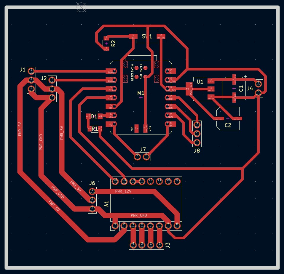
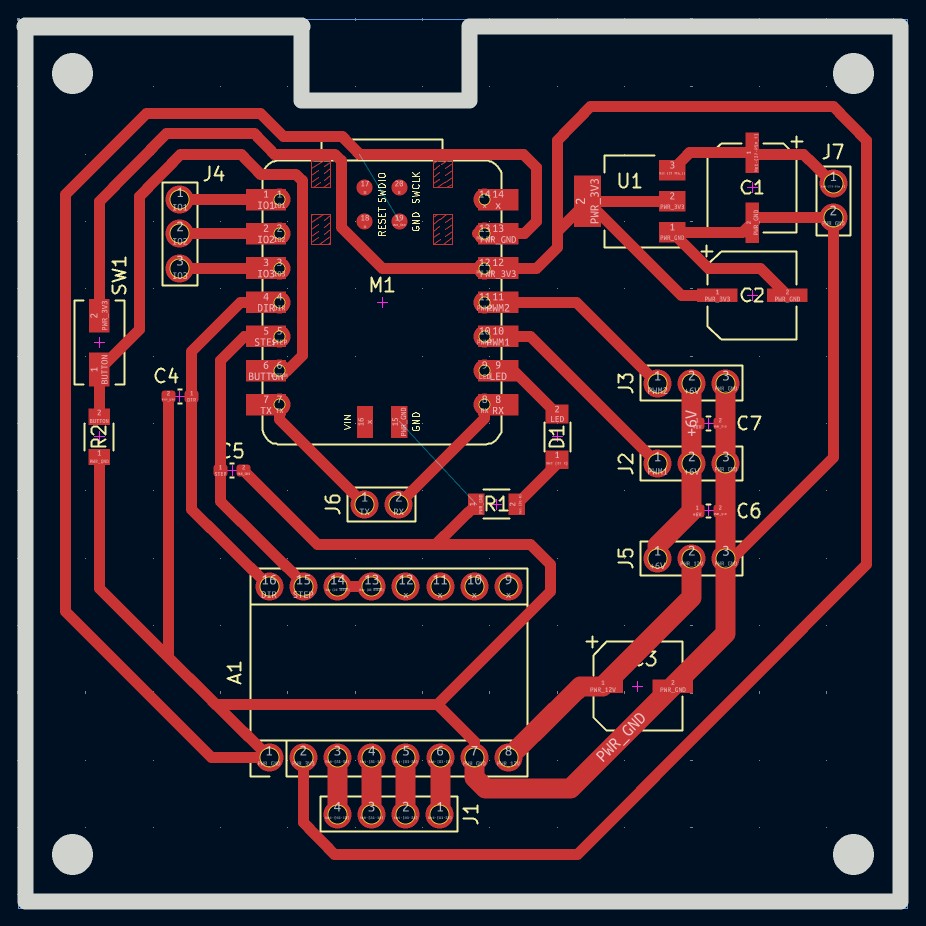
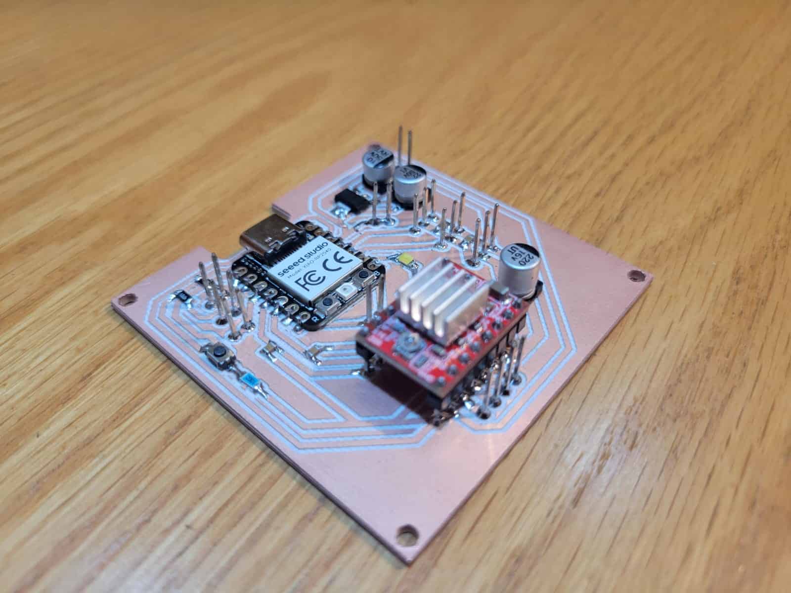
I have successfully designed and produced three different versions of a custom PCB based on the XIAO RP2040 microcontroller:
- Version 1 (V1) - Initial development board created during the Electronic Design and Electronic Production weeks. This board allowed me to experiment with basic input and output devices.
- Version 2 (V2) - Improved board created during Output Devices week, introducing more reliable power handling, separated voltage lines for different components, and noise reduction through strategic placement of capacitors.
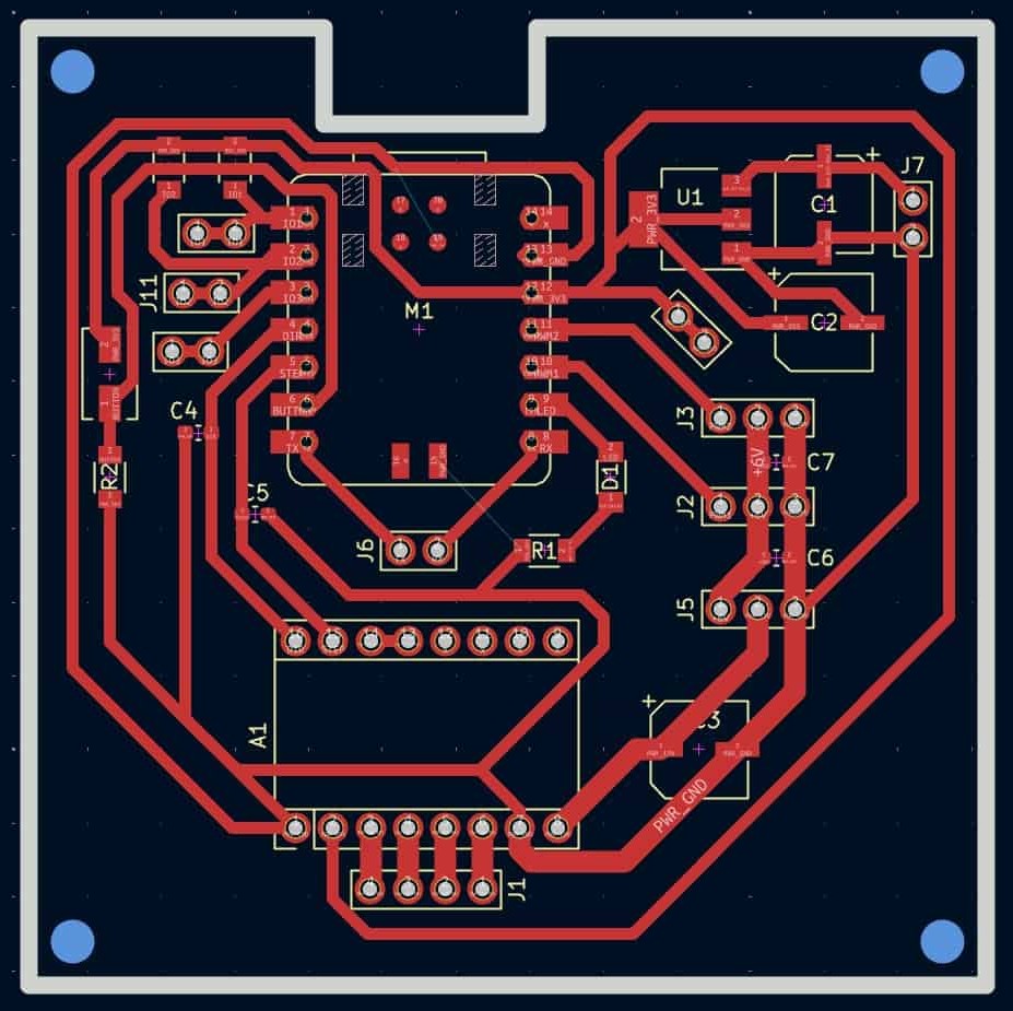
- Version 3 (V3) - Final communication-focused version produced during Networking and Communications week. It introduced integrated pull-up resistors for I²C communication and additional connectors for modularity, additionally it's production process was by far the cleanest.
Each iteration has built upon the previous one, reflecting continuous improvements in both circuit design and PCB manufacturing techniques.
1.2 Inputs and Outputs Experimentation
- Input - Successfully integrated the OpenMV H7 camera as a vision-based input device capable of detecting human facial features and sending simple UART-based commands.
- Outputs - Controlled high-torque DS3218 servomotors and a Nema 17 stepper motor through the A4988 driver, validating the ability of my PCB to handle various types of actuators.
- Systems Communication- Developed an I²C network using three XIAO RP2040 boards, demonstrating successful main-secondary communications with physical actions triggered via button inputs and LED outputs.
Through these tests, I have gained crucial experience in embedded system integration, circuit design refinement, and communication protocols — all critical foundations for the final project.
2. Remaining Tasks and Schedule
To complete my final project successfully, I have identified the following major tasks:
2.1 Mechanical Structure Redesign and Fabrication
- Current situation: The mechanical design done during Computer-Aided Design (Week 2) was rushed and lacks the refinement and functionality needed.
- Plan:
- Design two alternative mechanical platforms:
- Robotic Arm with multiple degrees of freedom.
- Pan-Tilt Turret system offering two-axis movement.
- Evaluate both systems based on stability, responsiveness, and ease of integration.
- Select the best option based on testing results and fabricate it using appropriate methods (laser cutting, 3D printing, CNC milling).
- Design two alternative mechanical platforms:
2.2 Further Software Development
- Camera Data Processing: Develop more sophisticated image-processing algorithms with the OpenMV H7 to accurately track or recognize desired features or objects.
- Motor Control Integration: Write optimized code to translate the processed input data into real-time motor movements on the mechanical system.
- Testing and Iteration: Continuously test motor responses, refine control algorithms, and ensure smooth, reliable operation.
2.3 System Integration and Power Management
- Power System Finalization: Select and integrate an appropriate power source that can supply stable voltages and currents to the microcontroller, servos, and stepper motors.
- Electrical Safety Improvements: Finalize the use of security measures like relays and optocouplers on the motor control PCB to ensure safe operation under all conditions.
2.4 Final Assembly and Aesthetic Refinement
- Final Physical Enclosure: Design and fabricate a professional-looking enclosure that protects the electronics, organizes the wiring, and improves the overall appearance.
- Polishing the Final Prototype: Apply finishing techniques such as sanding, painting, or coating to achieve a visually and functionally polished prototype ready for final presentation.
3. Timeline for Completion
| Task | Week(s) | Status |
|---|---|---|
| Mechanical design of two systems | Week 14-15 | Complete |
| Fabrication of prototypes | Week 15-16 | Complete |
| Selection of final mechanical system | Week 16 | Complete |
| Software development (camera + motor control) | Week 16-17 | Complete |
| Power system integration and testing | Week 17 | Complete |
| Full system integration and first full tests | Week 17-18 | Complete |
| Final mechanical assembly and finishing | Week 18 | Complete |
| Final debugging and polishing | Week 19 | Complete |
| Final documentation and video preparation | Week 19-20 | Complete |
I am confident that the progress made so far has established a solid foundation for my final project. I have gained critical skills in PCB design, microcontroller programming, input/output system integration, and communication protocols. The remaining work mainly involves mechanical system refinement and full integration of hardware and software components. I am fully committed to completing the project following the proposed schedule, perhaps even being able to get ahead of schedule.
System Integration
This section corresponds to Week 15: System Integration, where the goal is to bring together all the elements of the final project into a cohesive, working system. The objective is not just to have each component functional in isolation, but to ensure that they work harmoniously together — mechanically, electronically, and programmatically — as part of a real-world application. For my project, this meant ensuring that my robotic vision-based arm could reliably detect, interpret, and react to human presence with physical movement.
The final system is composed of a 3D-printed robotic arm equipped with a custom PCB based on the XIAO RP2040, a NEMA 17 stepper motor (soon to be upgraded with a planetary gearbox), two high-torque DS3218 servo motors, and an OpenMV H7 AI camera. The camera runs a FOMO-based machine learning model to detect a human target, sending interpreted positional data via UART to the RP2040, which controls the servos in real time to adjust the elevation and reach of the arm accordingly. The system is designed to extend the arm toward a detected person and retract when no person is present.
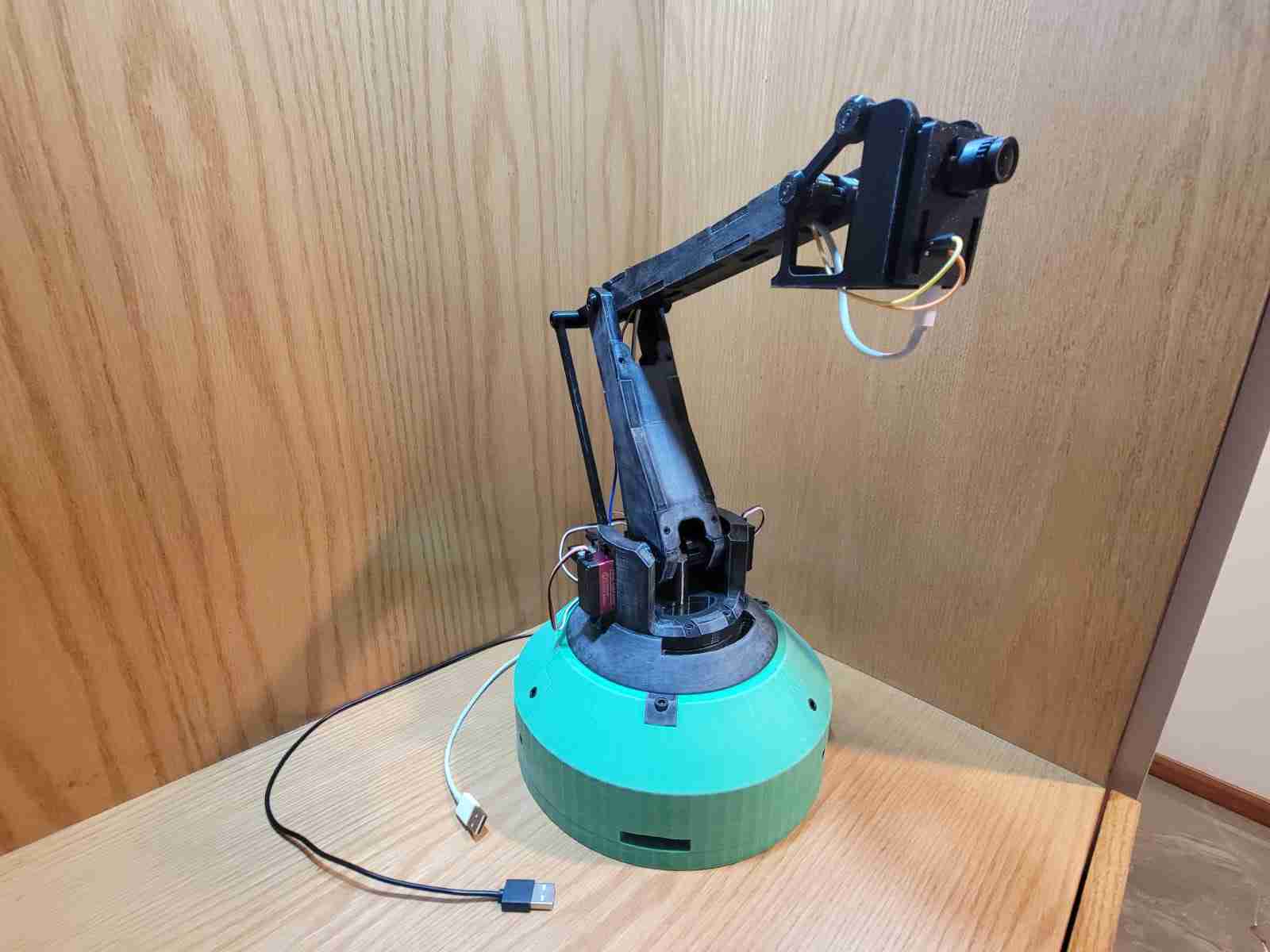
Mechanically, the project emphasizes modular design and manufacturability through 3D printing. Each part was designed to fit using press-fit geometry and reinforced with screws. A key feature is the implementation of a perfect parallelogram mechanism in the upper linkages of the arm, which stabilizes the orientation of the end effector (camera) regardless of arm position. This solution was the result of careful research and multiple design iterations. The base also houses a 78mm axial ball bearing to allow low-friction rotation, and the entire arm structure was optimized for smooth motion through custom axial joints.
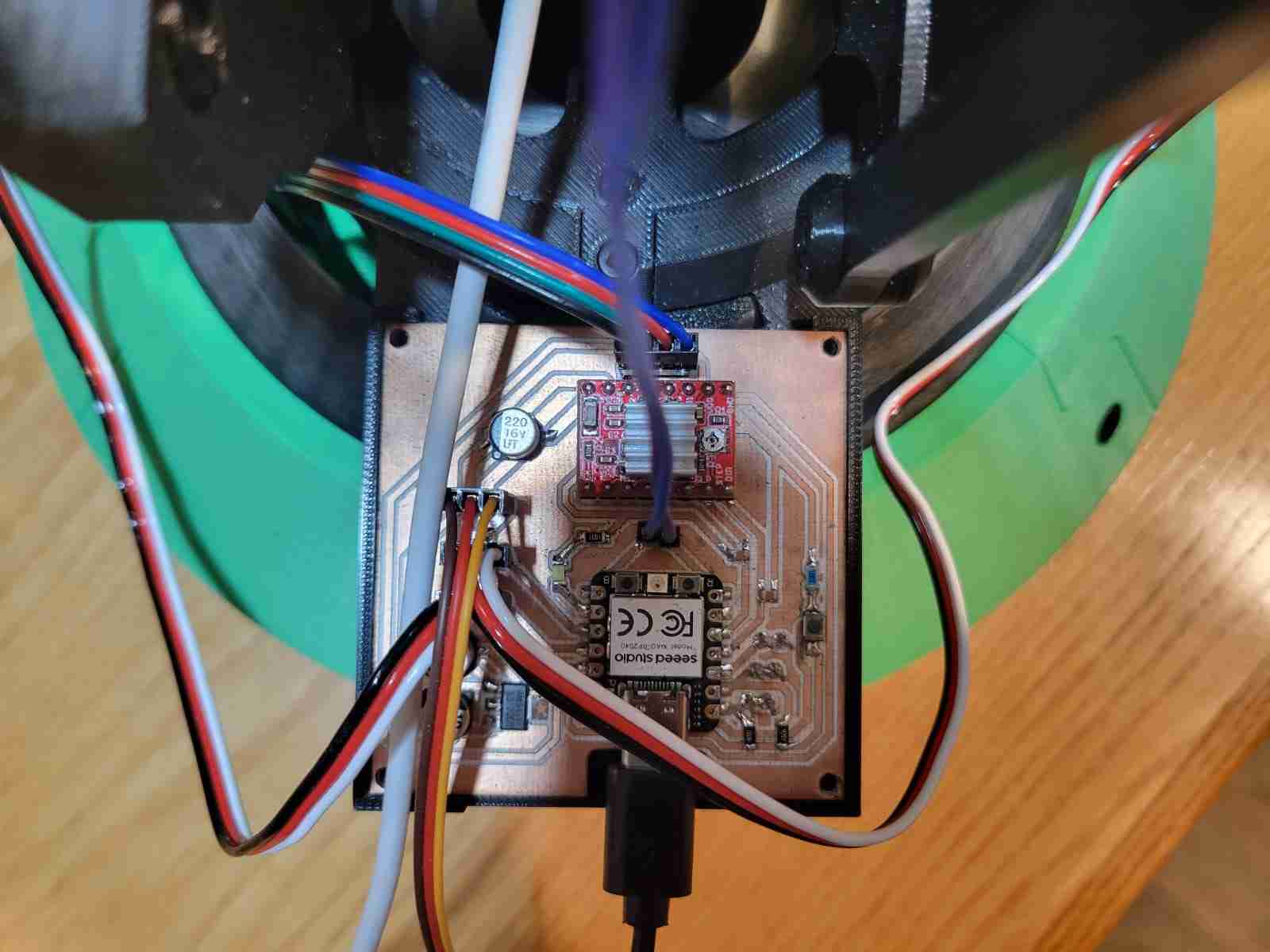
The electronics are fully integrated onto a compact PCB that not only powers the system but also serves as a central communication node. It includes headers for the stepper driver (A4988), servo connections, power inputs (5V and 12V), and UART/I²C lines. The camera communicates with the RP2040 over UART, while the board itself is mounted to rotate with the arm, reducing the complexity of cable management. All wires from the servos and camera are routed internally through the structure, exiting cleanly at the base. A potential future improvement is the addition of a slip ring to allow for continuous 360° base rotation.
The programming side consists of two coordinated codebases. The OpenMV script performs continuous image capture and detection, sending vertical position offsets and presence signals via serial communication. The RP2040 interprets these messages, gradually adjusting servo angles within constrained safety limits to prevent damage or erratic motion. Motion is smoothed through incremental updates and range clamping, ensuring a responsive but controlled behavior.
Testing confirmed the effectiveness of the communication and motion coordination system, with the servos reacting accurately to the visual feedback from the camera. One limitation discovered was the stepper motor’s inability to rotate the full arm assembly due to torque constraints, leading to the decision to upgrade to a gearbox-equipped version (10:1 or 14:1). Despite this, the vertical and forward motions of the arm were fully functional and stable.
A major part of system integration was also the packaging and finish of the design. Surface sanding was carried out in multiple stages (60 to 600 grit) to ensure a smooth texture, with plans for priming and painting to give the final product a polished, professional appearance. The mechanical layout, wire management, and enclosure planning reflect a strong intention to design this prototype as a near-finished product, not just a functional experiment.
In conclusion, this system integration process allowed me to validate the full functionality of my project under real-world conditions. It represents the culmination of everything learned during the FabAcademy — from 3D design and electronics production to embedded programming and interface development. Every subsystem has been engineered to work together as a unified whole, and the result is a responsive, intelligent, and adaptable robotic platform ready for future refinement and expansion.
Applications and Implications
This section corresponds to Week 17: Applications and Implications, where the focus is on defining, planning, and evaluating the final project's development. The objective is not just to describe what the project is, but to anticipate its performance, assess its viability, and ensure that it meets the criteria of an independently operable, skill-integrated masterpiece. For my project, this meant deeply analyzing what would be designed, what materials and processes would be required, what needed to be tested, and what still needed to be resolved to bring the system to full functionality.
My final project is a computer vision-based robotic arm that tracks a human subject using an OpenMV H7 camera. The system includes two servo-controlled axes (height and extension) and a stepper-controlled base. These are managed through a custom PCB based on the XIAO RP2040, making it an autonomous tracking turret for applications such as surveillance or interaction.
The concept draws inspiration from the Jet Max robotic arm and the mechanical design leverages a parallelogram linkage to stabilize the camera during movement. This ensured both structural reliability and a clear view from the end effector.
I designed the entire structure and created a custom PCB to coordinate all movement based on image data. The design incorporates all Fab Academy disciplines: 2D and 3D design, additive and subtractive fabrication, electronics production, and software development.
The Bill of Materials includes PLA for the 3D-printed structure, DS3218 servos, a NEMA17 motor with a planetary gearbox, and various standard electronics. Materials were sourced from online vendors, while PCB components were provided by my local instructor. The total project cost is estimated around $196 pre-shipping and taxes.
Mechanical Components
| Item | Details | Quantity | Unit Price | Source / Link |
|---|---|---|---|---|
| PLA Filament | Black PLA | ~1.6 kg | $23.50 per kg | Link |
| Axial Ball Bearing | 78mm OD, 40mm ID, 26mm H | 1 | $5.68 | Link |
| M3 Screws & Nuts | Mixed lengths | TBD | N/A | N/A |
| M5 Screws | 12mm | 9 | N/A | N/A |
| M5 Screws | 16mm | 9 | N/A | N/A |
Electronic Components (External to PCB)
| Component | Specification | Quantity | Unit Price | Source / Link |
|---|---|---|---|---|
| DS3218 Servo Motor | 20kg high torque | 2 | $10.03 | Link |
| NEMA 17 Stepper Motor | 40mm, replaced by geared version | 1 | $8.21 | Link |
| OpenMV H7 Camera | with FOMO model support | 1 | $80.33 | Link |
| D-100A Power Supply | 5V / 12V dual output | 1 | $23.03 | Link |
| Dupont Cables | Assorted | ~30 | $4.08 for 120 unit bundle | Link |
| USB-C to USB-C Cable | Data + power | 1 | N/A | N/A |
| Micro USB to USB-A Cable | Data + power | 1 | N/A | N/A |
Custom V3 PCB Components
| Component | Specification / Package | Quantity | Unit Price | Source / Link |
|---|---|---|---|---|
| XIAO RP2040 | — | 1 | $4.64 | Link |
| A4988 Driver | — | 1 | $2.20 | Link |
| Resistor | 4700Ω, 1260 | 2 | N/A | N/A |
| Resistor | 1000Ω, 1260 | 1 | N/A | N/A |
| Resistor | 10000Ω, 1260 | 1 | N/A | N/A |
| LED | 1260 | 1 | N/A | N/A |
| Capacitor | 10nF, 0603 | 4 | N/A | N/A |
| Electrolytic Capacitor | 10µF | 1 | N/A | N/A |
| Electrolytic Capacitor | 22µF | 1 | N/A | N/A |
| Electrolytic Capacitor | 220µF | 1 | N/A | N/A |
| 3.3V Voltage Regulator | — | 1 | N/A | N/A |
| Push Button | — | 1 | N/A | N/A |
| Pin Header | 2-pin | 6 | N/A | N/A |
| Pin Header | 3-pin | 3 | N/A | N/A |
| Pin Header | 4-pin | 1 | N/A | N/A |
Processes used include 3D printing, CNC milling, laser cutting, and vinyl cutting, as well as painting for the final finish. Coding was done in both Python and C++ to enable real-time control and coordination between camera and actuators.
The main challenge yet to be solved is synchronizing all axes using the vision system, pending the integration of the new geared stepper. Testing and final programming will follow immediately after its installation. Once operational, the system will be evaluated by its ability to accurately track and follow a person, demonstrating full mechanical-electrical-software integration.
Final Development Log
As of the 9th of June, 2025, the project has reached is completion on both production and documentation. The itegration of a gearbox above the stepper motor was the solution to the previously encountered problem. After integrating said component, I was able to program the final version of the arm, which integrates all axes, has a patrol function and a better interface.
A final modification was the additon of a mesh tube to secure the cables on the inside and outside of the arm.