15. System Integration
Summary
This week I designed and documented the system integration for my final project.
1. What is System Integration?
System integration is the process of bringing together all the independent components of a project, which include mechanical structures, electronic circuits, sensors, actuators, and software, with the purpose of creating a single, cohesive system that functions reliably and as intended. In the context of digital fabrication and embedded systems, integration ensures that all subsystems communicate and operate in harmony to accomplish a shared goal.
This step involves both physical assembly and logical coordination: assembling mechanical parts, wiring and connecting electronic boards, uploading and linking the software, and testing interactions across the entire system. The purpose is to move from individual subsystems to a final prototype that performs complex tasks as a single unit.
2. My final system
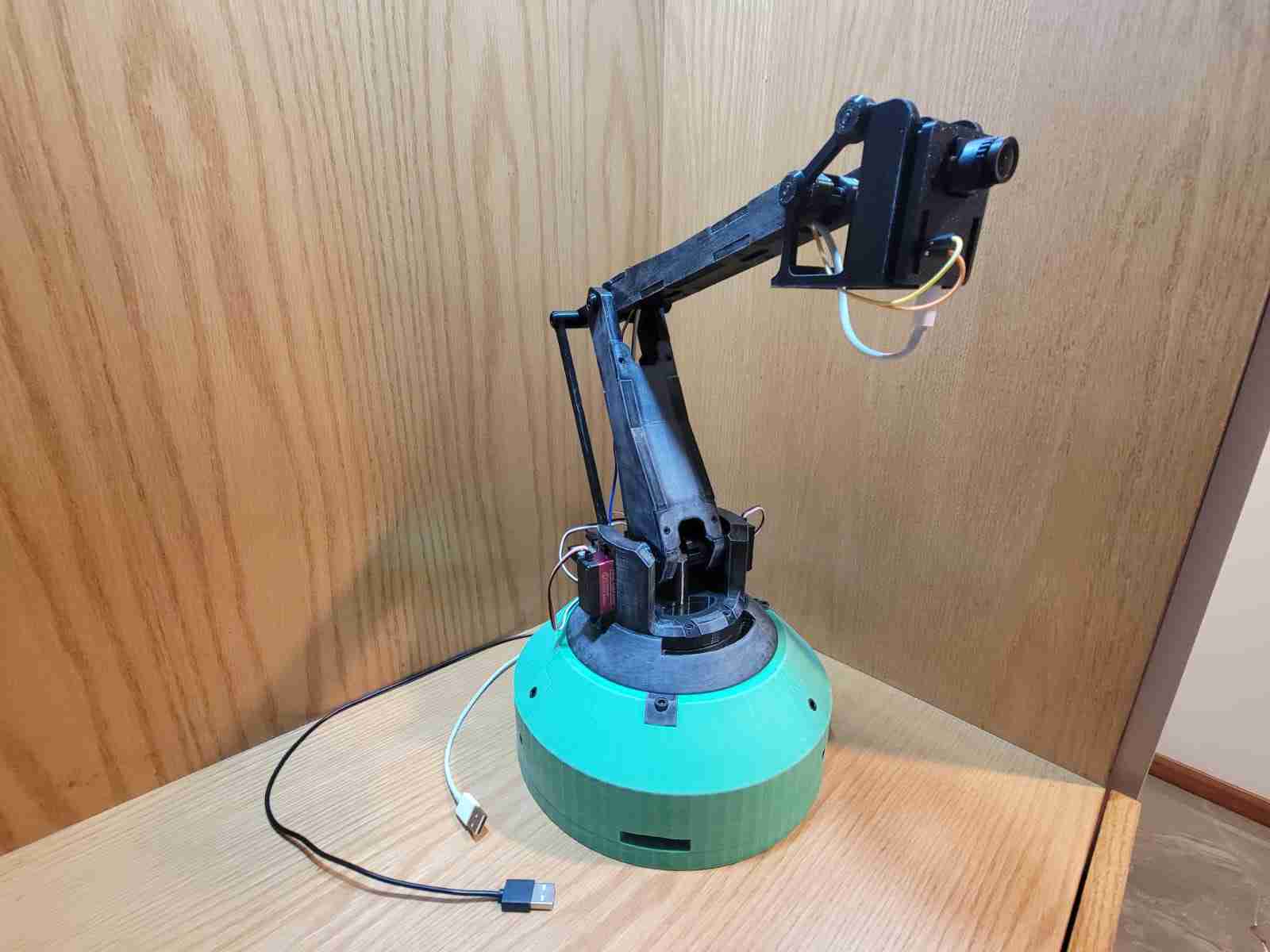
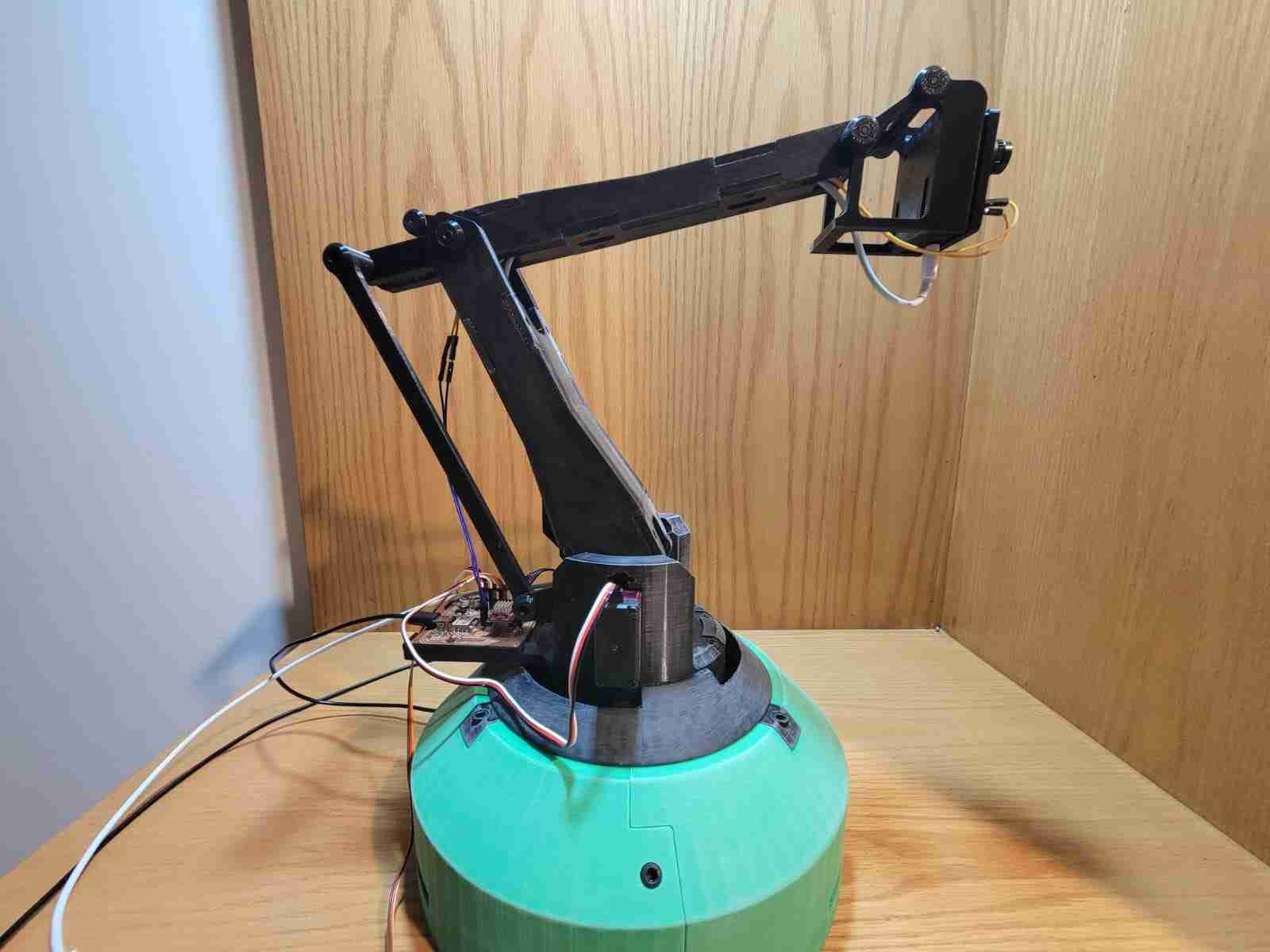
My final project is a computer vision-guided robotic arm designed to detect and track human subjects in real time. The system consists of a custom-built, 3D-printed articulated arm with three degrees of freedom, actuated via high-torque servo motors and a stepper motor, and controlled by a XIAO RP2040 microcontroller. The arm integrates an OpenMV H7 AI camera, which is responsible for performing image processing and target recognition.
The primary function of the system is to keep the camera stabilized and continuously oriented toward a human face or body as detected by the vision module.
Hero Shot:
3. Materials
The following tables outline the components used in my final project, categorized by mechanical structure, external electronics, and components used in my custom V3 PCB.
3.1 Mechanical Components
| Item | Details |
|---|---|
| PLA filament | Approx. 1565g |
| Axial Ball Bearing | 78mm outer, 40mm inner, 26mm height |
| M3 Screws & Nuts | Various lengths and quantities (TBD) |
| M5 Screws | 9x 12mm, 9x 16mm |
3.2 Electronic Components (External to PCB)
| Component | Quantity |
|---|---|
| DS3218 Servo Motor | 2 units |
| NEMA 17 Stepper Motor (48mm) | 1 unit |
| OpenMV H7 Camera | 1 unit |
| D-100A Dual Output Power Supply (5V, 12V) | 1 unit |
| Dupont Cables | Assorted |
| USB Type-C to Type-C Cable | 1 unit |
| Micro USB to USB-A Cable | 1 unit |
3.3 Custom V3 PCB Components
| Component | Specification / Package | Quantity |
|---|---|---|
| XIAO RP2040 | — | 1 |
| A4988 Stepper Driver | — | 1 |
| Resistor | 4700Ω, 1260 | 2 |
| Resistor | 1000Ω, 1260 | 1 |
| Resistor | 10000Ω, 1260 | 1 |
| LED | 1260 | 1 |
| Capacitor | 10nF, 0603 | 4 |
| Electrolytic Capacitor | 10µF | 1 |
| Electrolytic Capacitor | 22µF | 1 |
| Electrolytic Capacitor | 220µF | 1 |
| 3.3V Voltage Regulator | — | 1 |
| Push Button | — | 1 |
| Pin Header | 2-pin | 6 |
| Pin Header | 3-pin | 3 |
| Pin Header | 4-pin | 1 |
4. Mechanical Design
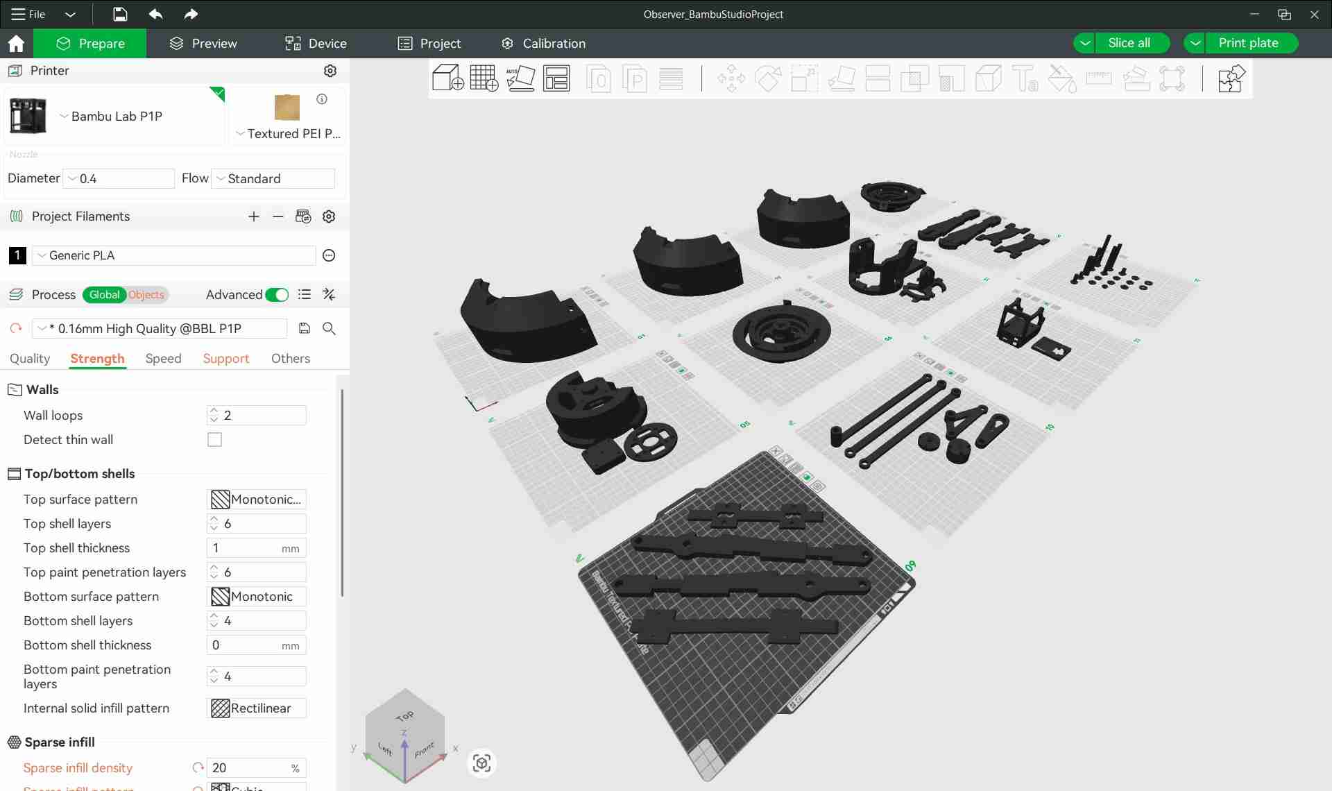
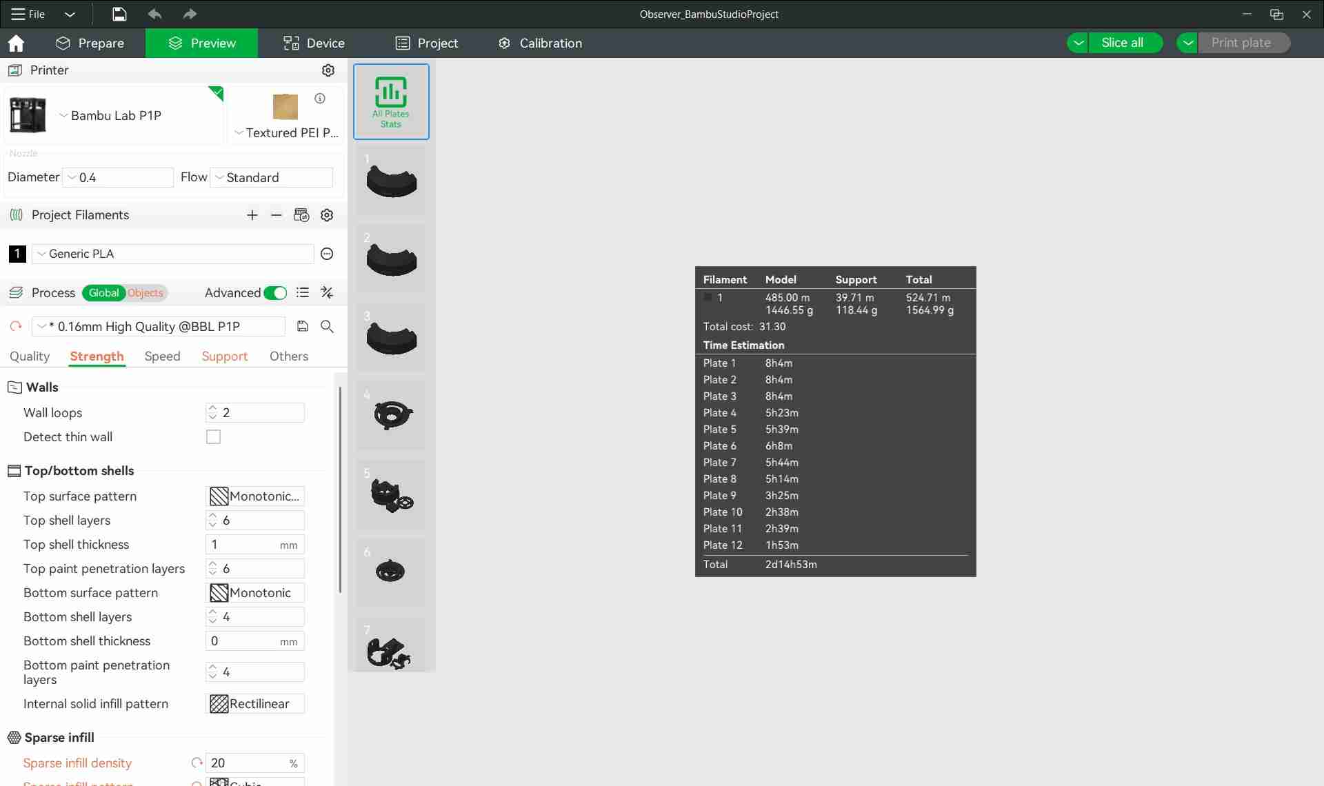
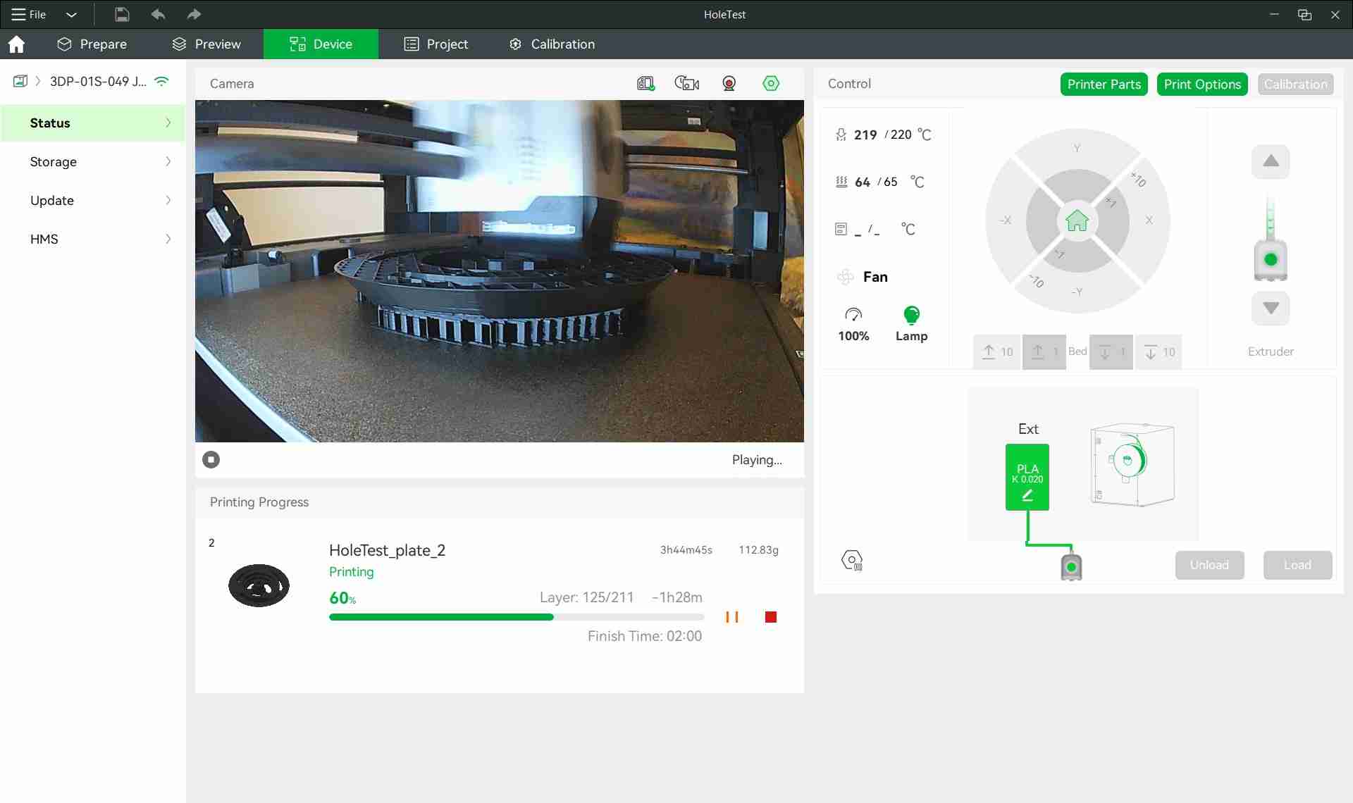
The mechanical structure of my final project was designed with a strong focus on modularity, precision, and ease of fabrication, leveraging the strengths of Fused Deposition Modelling 3D printing. All components were produced in PLA filament, with a total material usage of approximately 1565 grams and a cumulative print time of around 63 hours.
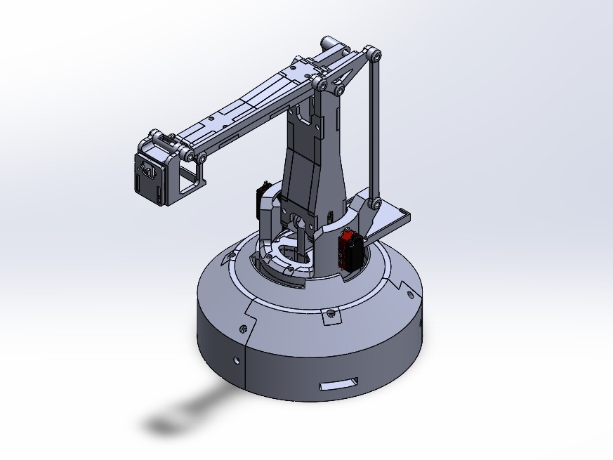

The design philosophy centered around dividing the system into many interlocking parts. Each section was created with press-fit geometries to allow for initial alignment during assembly, followed by screw reinforcement to secure the final structure. This hybrid approach makes the assembly sturdy while keeping rework possible during testing or upgrades.
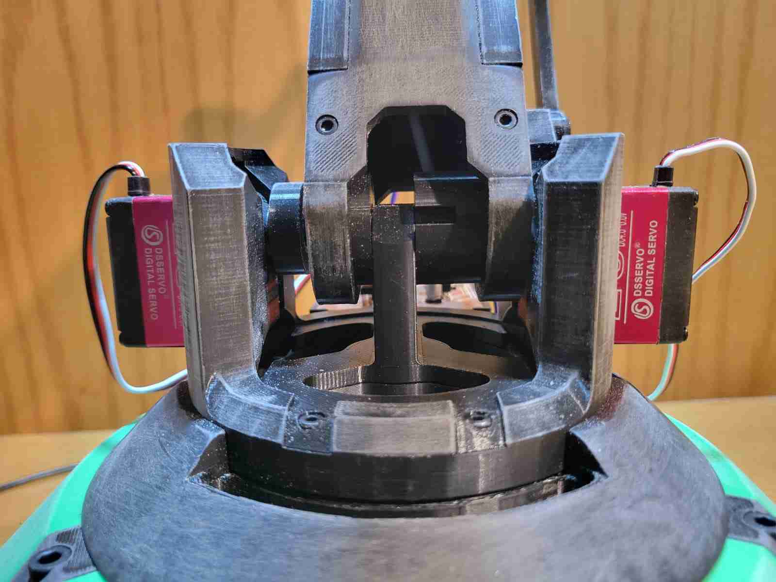
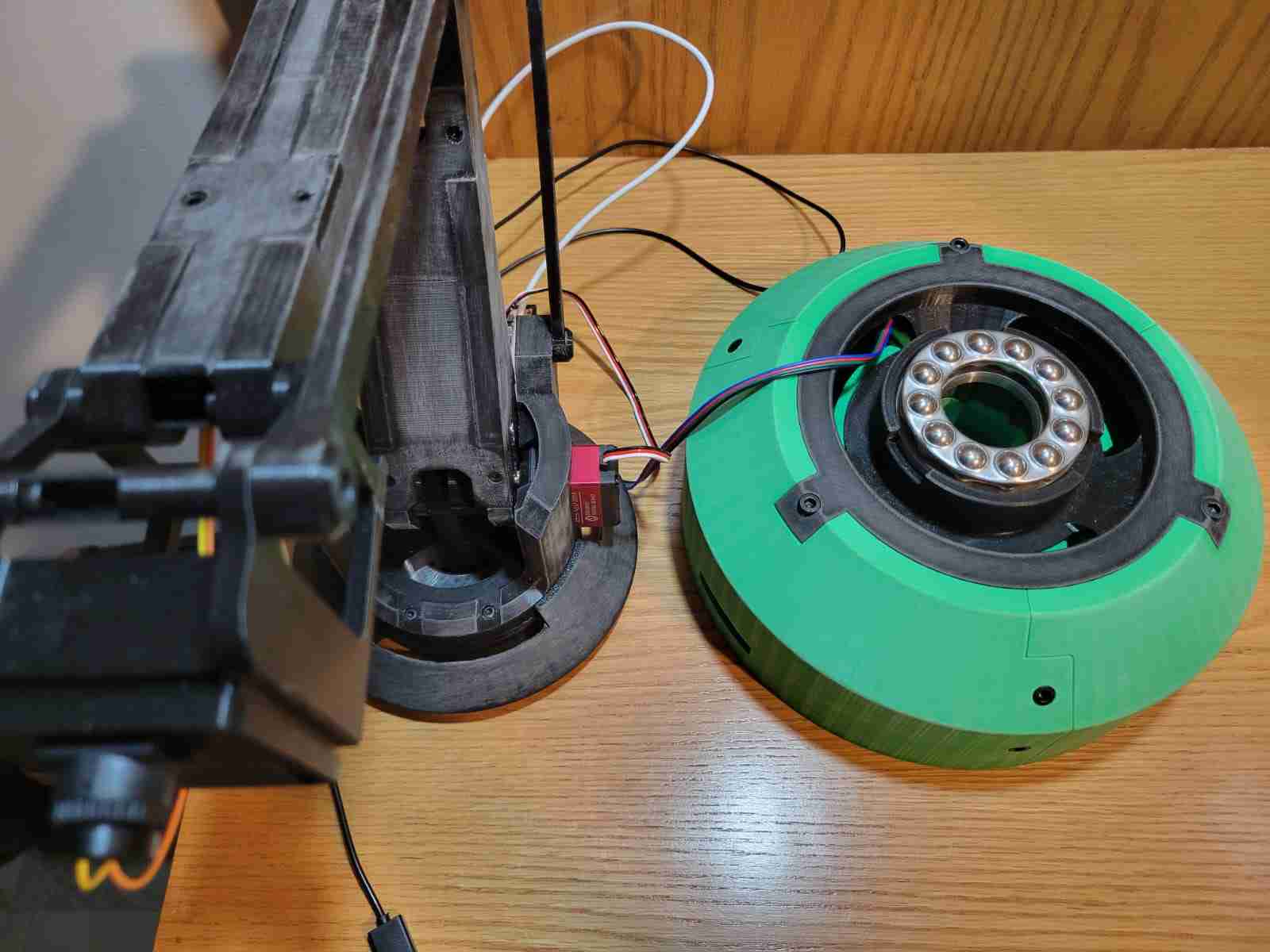
Motion in the arm structure is enabled by multiple axial rods acting as structural pivots. These rods are stabilized using custom-designed end caps with nut sockets, allowing for reliable tightening while still maintaining loose enough tolerances for smooth rotational movement. The base includes a dedicated housing for a 78mm axial ball bearing, which significantly reduces friction during base rotation and adds durability under load.
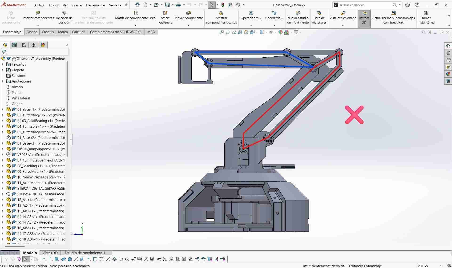
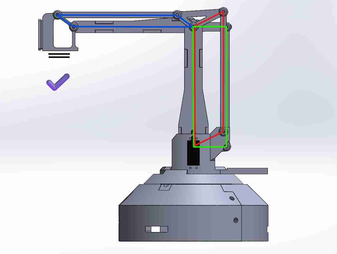
A crucial improvement to the mechanical performance of the arm was the implementation of a perfect parallelogram mechanism to stabilize the end effector. During early physical testing, it became apparent that the camera's orientation would drift, particularly when the arm extended fully. Through research and comparison with professional robotic arm designs, I identified the geometric constraints of a parallelogram linkage as a reliable way to maintain orientation. This insight led to a redesign of the upper linkages so that opposite segments remain equal and parallel throughout movement, ensuring the camera stays horizontally aligned at all times. This not only improved stability but gave the arm a more professional behavior when tracking targets.
In terms of scale, the system is quite large. The circular base has a diameter of 250mm, and each of the two primary arm segments measures 200mm in length. This gives the arm a maximum horizontal reach of around 350mm, providing substantial coverage for scanning and tracking purposes.
The design also includes dedicated mounts for all key components, such as the DS3218 servo motors, NEMA 17 stepper motor, OpenMV H7 camera, axial bearing, and the custom RP2040-based PCB. These mounts are reinforced with screw slots to ensure each component can be fixed firmly in place when needed.
During integration testing, a significant mechanical limitation emerged: the NEMA 17 stepper motor installed to rotate the base was unable to generate sufficient torque to overcome the combined weight and friction of the full arm assembly. Despite being a commonly used motor for moderate-load applications, it proved underpowered for this specific configuration, particularly at the outer edge of its torque curve. As a result, the base was left non-functional in rotation during early trials. To resolve this, I plan to upgrade the system with a higher torque NEMA 17 motor equipped with a planetary gearbox, either with a 10:1 or 14:1 gear ratio, depending on further testing. This modification is expected to provide the mechanical advantage needed for smooth and reliable base rotation.
Overall, the mechanical design prioritizes functionality, ease of maintenance, and adaptability, making it a solid foundation for the integration of electronics and control systems in the following stages of the project.
The design files for this project are quite heavy and I will probably be making modifications to the final design, so I will refrain from uploading them until the final project is complete.
5. Electronic Design
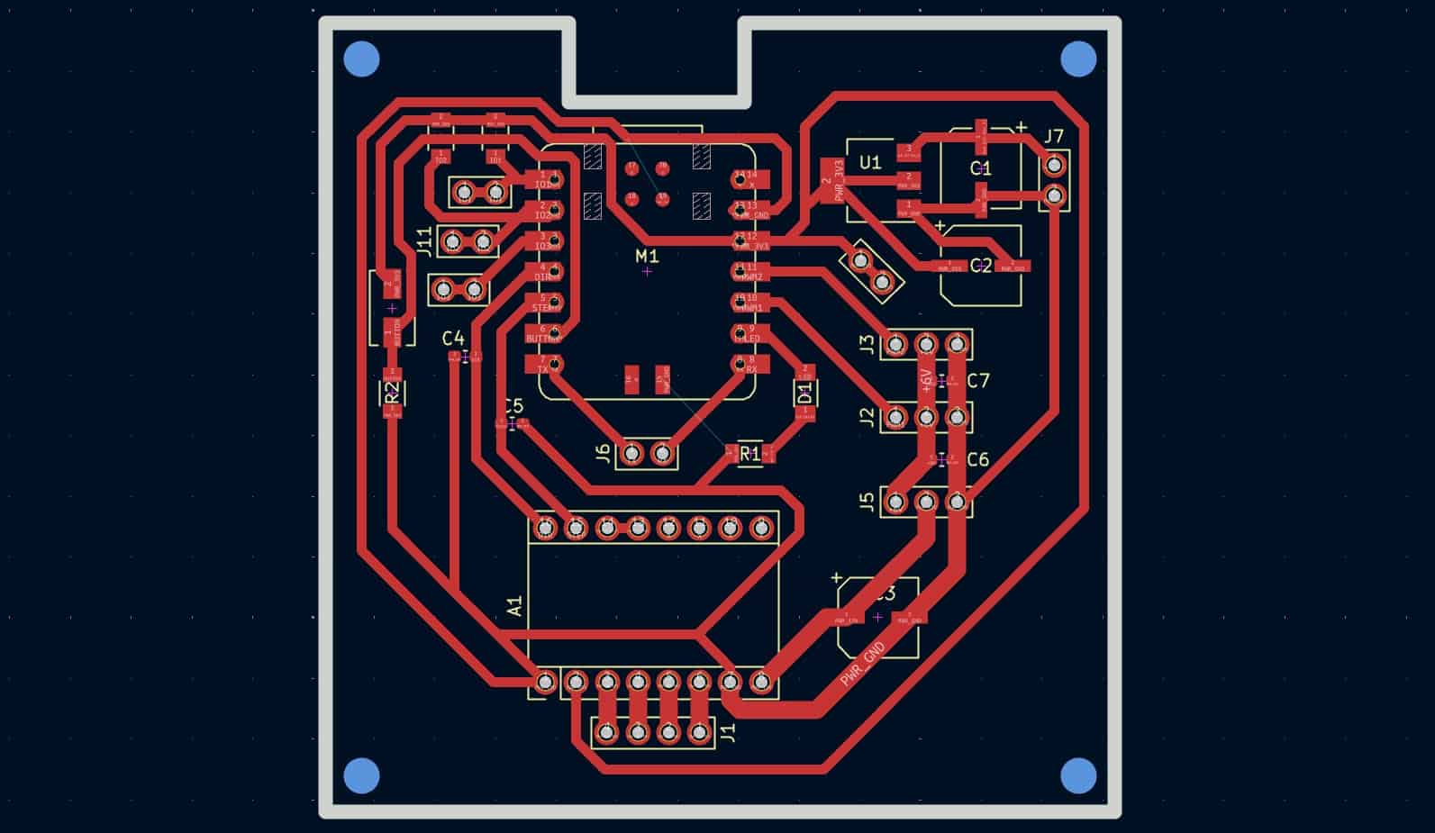
The electronic system of the project revolves around a custom-designed PCB built around the Seeed Studio XIAO RP2040 microcontroller. This PCB was designed during week 11 and it will serve as a centralized hub for all control and communication functionalities, particularly motor actuation and camera interaction.
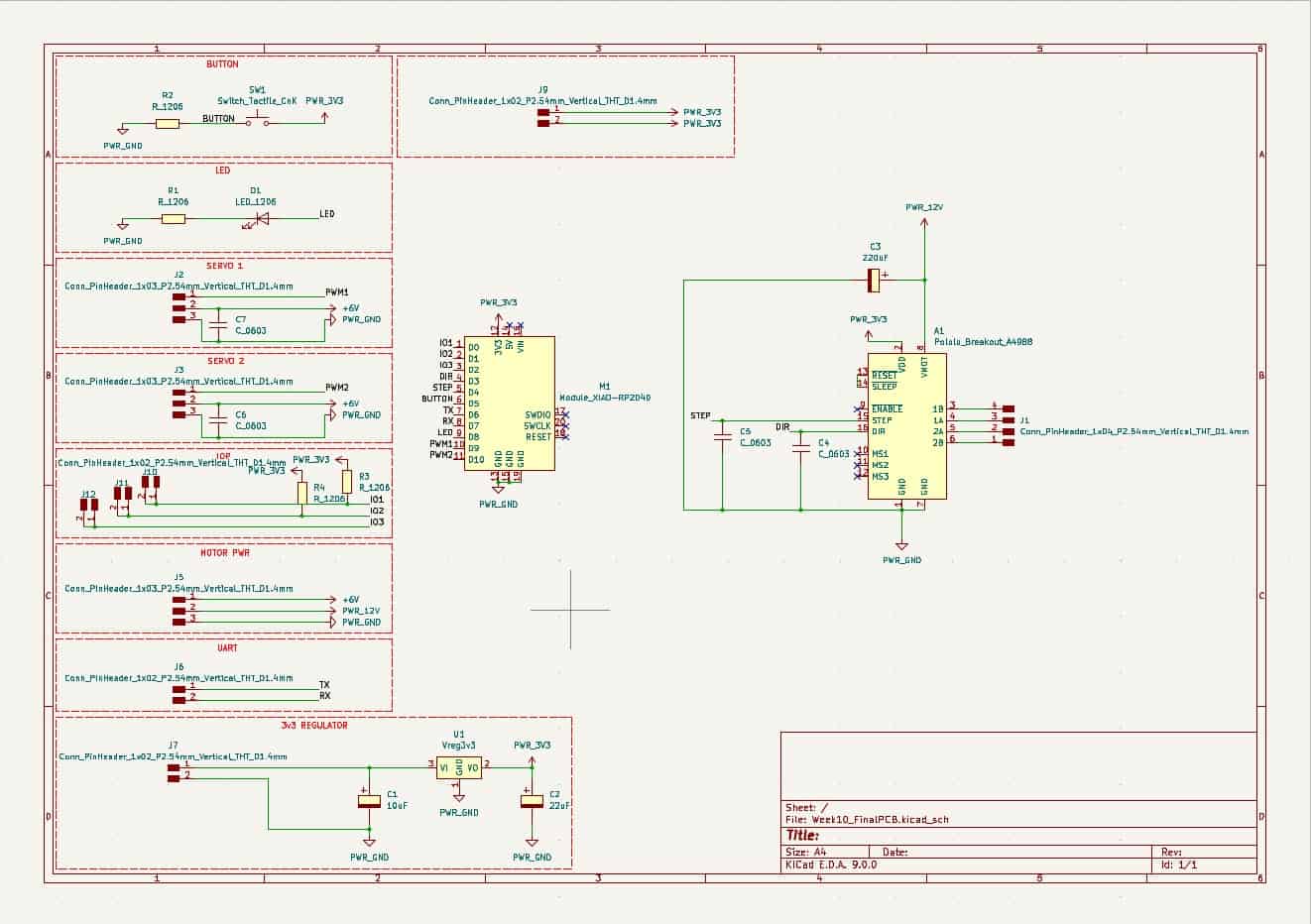
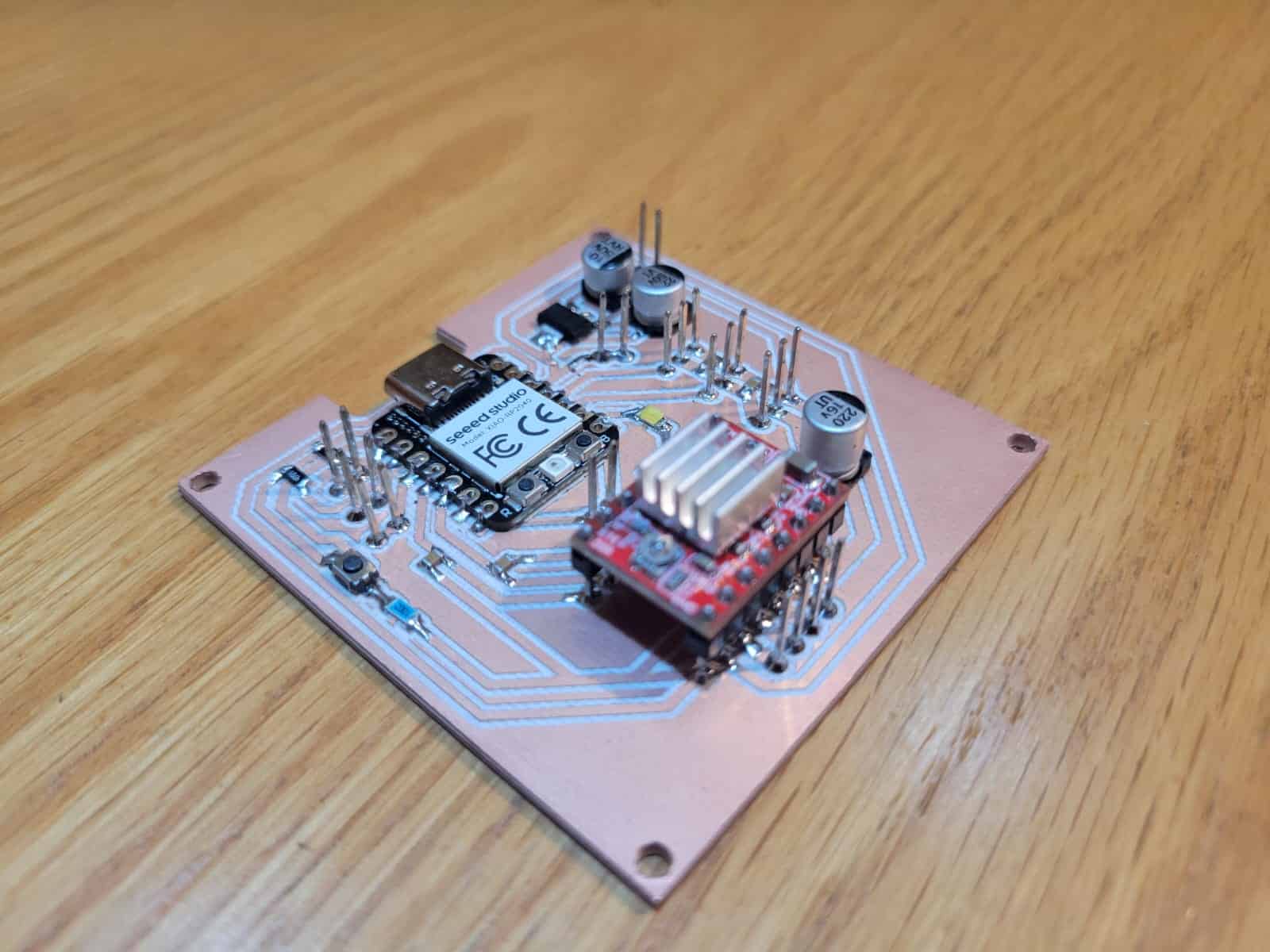
The board features direct connections to both high-torque DS3218 servo motors and a NEMA 17 stepper motor via an onboard A4988 stepper driver. Each motor type is powered through dedicated power lines, with the stepper motor being supplied by a 12V power line and the servos being powered through a 5V power line, both provided by a dual-output D-100A power supply.
For communication, the PCB includes UART lines specifically allocated for connection with the OpenMV H7 camera. These pins are actively used during system operation, enabling the microcontroller to receive commands based on computer vision outputs. Additionally, two I/O pins are configured with I²C pull-up resistors, providing future flexibility for integrating additional I²C-based sensors or modules.
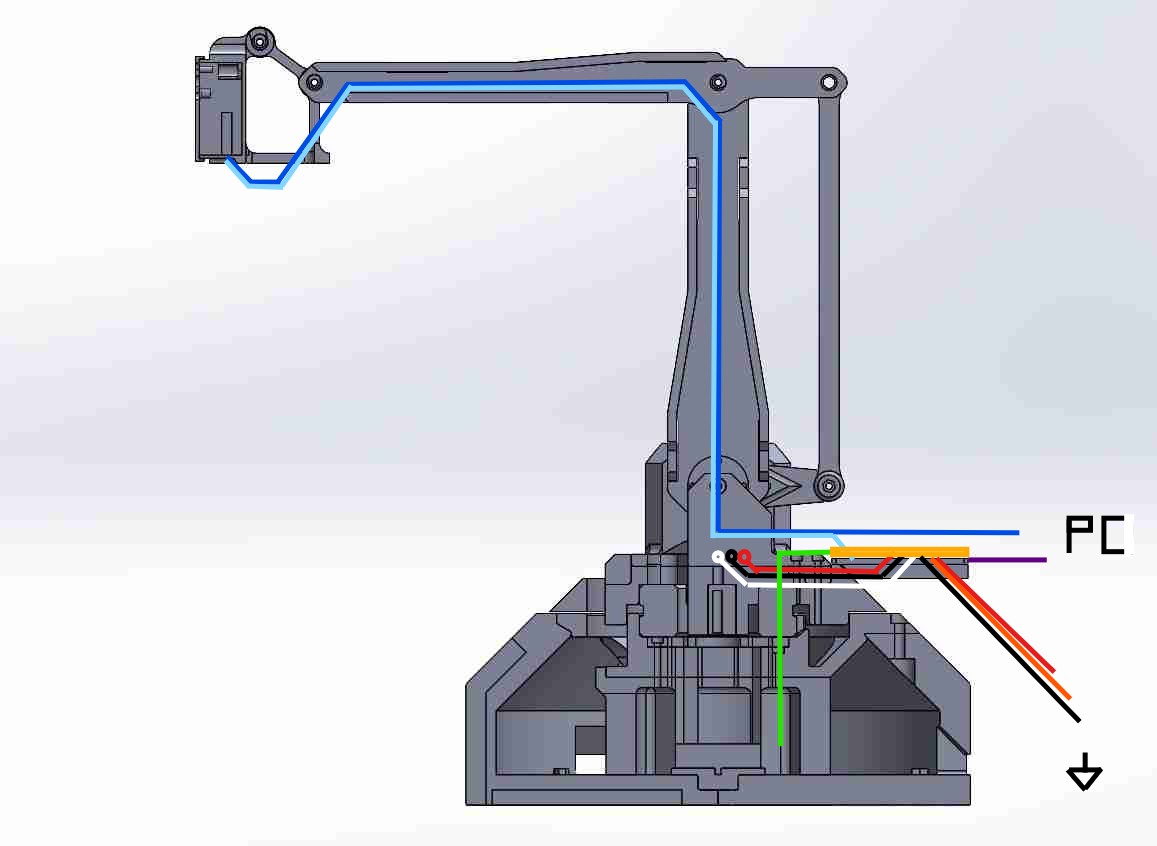
Once fully wired, the system includes a total of 17 individual cables:
- 3 cables for power input (5V, 12V, and GND)
- 6 cables for the operation of the servo motors, these being signal, power and ground lines
- 2 cables for UART communication (TX and RX)
- 4 cables for the stepper motor
- 1 USB Type-C cable for the XIAO RP2040's programming and communication with a PC
- 1 Micro USB cable for the OpenMV H7 cam's programming and communication with a PC
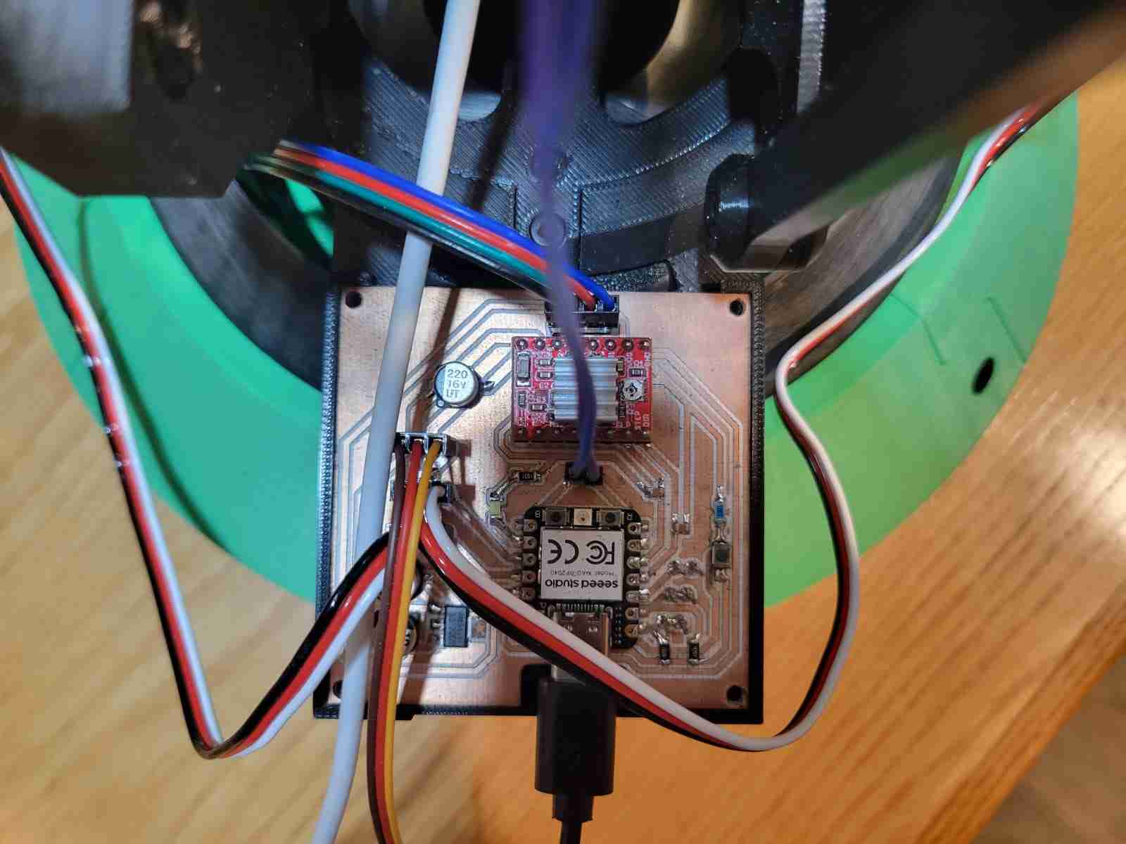
All cables routed from the camera travel internally through the articulated structure of the arm until reaching the base. From there, the UART wires connect directly to the PCB, and the USB cable exits the structure for connection to the host computer. This design minimizes external wiring clutter and ensures consistent connectivity between moving components.
The PCB itself is mounted at the rear of the turntable assembly, rotating with the main body of the arm. This design choice greatly simplifies cable management during rotation; however, it does introduce a limitation: cable twisting of the NEMA 17 cables after multiple full rotations. This issue could be resolved in the future by integrating a slip ring, which would allow for uninterrupted 360° rotation without cable entanglement — a highly recommended upgrade for continuous-duty versions of this system.
Overall, the electronic architecture seeks a balance of control, communication, and mechanical integration, forming a critical bridge between the sensing and actuation layers of the robotic arm.
6. Programming
The programming component of my final project integrates two interdependent systems: one running on the OpenMV H7 camera and the other on the XIAO RP2040. Together, these systems form the backbone of the control logic for real-time human detection and responsive servo motion.
6.1 OpenMV Vision System
The OpenMV H7 camera is tasked with detecting human subjects using a pre-trained FOMO (Fast Object Detection Model). The camera captures video at 240x240 resolution and processes each frame to detect faces or bodies. When a subject is detected, the camera extracts the coordinates of the detection's center and calculates the vertical offset from the image's midpoint. Based on this offset, it determines whether to send movement commands to adjust the elevation of the arm.
In addition, whenever a person is detected, the camera sends the string "PRESENT" over UART. If no person is detected, it sends "ABSENT". This enables the RP2040 to manage forward/backward motion independently. The OpenMV communicates over UART3 at 115200 baud, and uses simple serial strings such as Y:-25 to signal vertical misalignment and drive correction.
The code also includes logic to ignore small vertical offsets (within ±10 pixels), preventing unnecessary jitter in the servos. Each UART message ends with a newline character to ensure clean parsing by the RP2040.
										import sensor, time, ml, math, image, pyb
from ml.utils import NMS

sensor.reset()
sensor.set_pixformat(sensor.RGB565)
sensor.set_framesize(sensor.QVGA)
sensor.set_windowing((240, 240))
sensor.skip_frames(time=2000)

model = ml.Model("fomo_face_detection")
uart = pyb.UART(3, 115200)

threshold_list = [(math.ceil(0.4 * 255), 255)]
colors = [(255, 0, 0), (0, 255, 0)]

def fomo_post_process(model, inputs, outputs):
    n, oh, ow, oc = model.output_shape[0]
    nms = NMS(ow, oh, inputs[0].roi)
    for i in range(oc):
        img = image.Image(outputs[0][0, :, :, i] * 255)
        blobs = img.find_blobs(threshold_list, x_stride=1, area_threshold=1, pixels_threshold=1)
        for b in blobs:
            rect = b.rect()
            x, y, w, h = rect
            score = img.get_statistics(thresholds=threshold_list, roi=rect).l_mean() / 255.0
            nms.add_bounding_box(x, y, x + w, y + h, score, i)
    return nms.get_bounding_boxes()

frame_center_y = 120  # Center of 240x240 frame
movement_threshold = 10  # How much vertical difference triggers a response

clock = time.clock()
while True:
    clock.tick()
    img = sensor.snapshot()
    person_detected = False

    for i, detection_list in enumerate(model.predict([img], callback=fomo_post_process)):
        if i == 0 or len(detection_list) == 0:
            continue

        person_detected = True
        for (x, y, w, h), score in detection_list:
            cx = int(x + w / 2)
            cy = int(y + h / 2)
            img.draw_circle((cx, cy, 10), color=colors[i])

            dy = cy - frame_center_y
            uart.write(f"Y:{dy}\n")

    uart.write("PRESENT\n" if person_detected else "ABSENT\n")
    time.sleep_ms(100)
1. Initialization
sensor.reset()
sensor.set_pixformat(sensor.RGB565)
sensor.set_framesize(sensor.QVGA)
sensor.set_windowing((240, 240))
sensor.skip_frames(time=2000)
This sets up the image sensor to capture in 240x240 RGB format, ideal for square aspect-ratio object detection. A brief delay ensures the camera stabilizes.
2. Model and UART Setup
model = ml.Model("fomo_face_detection")
uart = pyb.UART(3, 115200)
The FOMO model is loaded, and UART communication is initialized using UART3 at 115200 baud to connect with the RP2040.
3. Detection Post-Processing
def fomo_post_process(model, inputs, outputs):
    # Returns bounding boxes after filtering and scoring blobs.
This helper function processes model output by running non-maximum suppression (NMS) and calculating blob statistics for detection confidence.
4. Calculating Offset
center_y = int(y + h / 2)
dy = center_y - frame_center_y
uart.write(f"Y:{dy}\n")
This logic finds the vertical offset between the person's center and the image midpoint. If the person is below center, dy is positive; if above, negative. This is used to adjust the elevation servo.
5. Person Status Signal
uart.write("PRESENT\n" if person_detected else "ABSENT\n")
This line tells the RP2040 whether a person is in view. It triggers forward movement when PRESENT is received and retracts the arm when ABSENT is received.
6.2 XIAO RP2040 Motor Control System
The XIAO RP2040 receives serial data from the OpenMV and processes it to control two servos:
- Servo 1 (Elevation): operates between 0° (fully up) and 30° (down). The RP2040 adjusts this angle in small steps depending on the vertical offset (dy) received.
- Servo 2 (Forward/Back): operates between 70° (forward) and 180° (rest/back). When a person is present, the arm gradually moves forward. If no person is detected, it retracts to 180°.
To stabilize motion, the code limits the update rate and uses conservative increments (±1° per cycle) for both servos. This smooth control eliminates sudden jumps and ensures the servos are not overstressed.
The RP2040 reads each line of input, parses commands starting with Y:, and converts them into real-time servo adjustments. Directional commands such as PRESENT and ABSENT are used to gradually transition the arm's position based on tracking status.
#include <Servo.h>

Servo servo1;  // Elevation: 0 to 30
Servo servo2;  // Depth: 180 to 70

int servo1Angle = 15;  // Start in middle position
int servo2Angle = 180; // Start pulled back

void setup() {
  Serial1.begin(115200);
  servo1.attach(D9);
  servo2.attach(D10);
  servo1.write(servo1Angle);
  servo2.write(servo2Angle);
}

void loop() {
  static String input = "";
  while (Serial1.available()) {
    char c = Serial1.read();
    if (c == '\n') {
      processCommand(input);
      input = "";
    } else {
      input += c;
    }
  }
}

void processCommand(String cmd) {
  cmd.trim();
  if (cmd.startsWith("Y:")) {
    int dy = cmd.substring(2).toInt();
    if (abs(dy) > 10) {
      servo1Angle += (dy > 0) ? 1 : -1;
      servo1Angle = constrain(servo1Angle, 0, 30);
      servo1.write(servo1Angle);
    }
  } else if (cmd == "PRESENT") {
    if (servo2Angle > 70) {
      servo2Angle -= 1;  // Move slowly forward
      servo2Angle = constrain(servo2Angle, 70, 180);
      servo2.write(servo2Angle);
    }
  } else if (cmd == "ABSENT") {
    if (servo2Angle < 180) {
      servo2Angle += 1;  // Return slowly backward
      servo2Angle = constrain(servo2Angle, 70, 180);
      servo2.write(servo2Angle);
    }
  }
}
1. Servo and Angle Initialization
Servo servo1;
Servo servo2;
int servo1Angle = 15;
int servo2Angle = 180;
The first servo (elevation) starts at a neutral midpoint (15° in a 0-30° range). The second (reach) is fully retracted initially at 180° (range 70-180°).
2. Setup Function
void setup() {
  Serial1.begin(115200);
  servo1.attach(D9);
  servo2.attach(D10);
  servo1.write(servo1Angle);
  servo2.write(servo2Angle);
}
Serial communication is initialized and servos are attached to their corresponding pins. The servos are then written to their start positions.
3. Serial Listening Loop
void loop() {
  static String input = "";
  while (Serial1.available()) {
    char c = Serial1.read();
    if (c == '\n') {
      processCommand(input);
      input = "";
    } else {
      input += c;
    }
  }
}
The microcontroller accumulates incoming serial characters until a newline is detected. Then, it sends the complete command string to processCommand().
4. Vertical Servo Adjustment (Y offset)
if (cmd.startsWith("Y:")) {
  int dy = cmd.substring(2).toInt();
  if (abs(dy) > 10) {
    servo1Angle += (dy > 0) ? 1 : -1;
    servo1Angle = constrain(servo1Angle, 0, 30);
    servo1.write(servo1Angle);
  }
}
This snippet parses dy from a string like Y:-25. If the offset exceeds a 10-pixel threshold, the servo moves gradually in the required direction. The motion is constrained within safe limits.
5. Forward/Back Servo Motion
else if (cmd == "PRESENT") {
  if (servo2Angle > 70) {
    servo2Angle -= 1;
    servo2.write(servo2Angle);
  }
} else if (cmd == "ABSENT") {
  if (servo2Angle < 180) {
    servo2Angle += 1;
    servo2.write(servo2Angle);
  }
}
When a person is detected, the servo moves forward gradually by decrementing its angle. When no person is detected, it slowly returns to the resting position. The movement is slow and controlled to minimize vibration and stress.
This cooperative code architecture allows both boards to operate semi-independently while forming a closed-loop control system. The camera "sees" and thinks, while the RP2040 moves — a distributed, robust, and modular interaction strategy.
6.3 Cooperative Behavior
Together, the OpenMV and RP2040 systems function as a responsive, closed-loop interaction platform. The camera continuously monitors the field of view, sending precise commands to the microcontroller, which in turn manipulates the robotic arm. This configuration provides an efficient division of tasks: the camera handles all the computationally expensive vision processing, while the RP2040 handles the low-latency servo control in a synchronized manner.
This separation of tasks not only makes the system modular and easy to debug, but also ensures the real-time performance necessary for a responsive interactive robot. Additionally, the use of UART simplifies communication while allowing future expansions (e.g., additional sensors over I²C).
7. Testing
During the testing phase, the functionality of the system was validated in stages to ensure correct integration of mechanical, electronic, and programming elements. Each subsystem was individually verified before conducting full-system trials.
The most successful result was the accurate communication between the OpenMV H7 camera and the XIAO RP2040. The system responded reliably to human detection in real-time, adjusting the robotic arm's elevation and reach smoothly, based on serial commands interpreted from vertical offset and presence status.
The vertical servo (servo 1) responded stably, compensating for movement without overshooting or erratic behavior. The forward servo (servo 2) correctly retracted when no person was detected, mimicking an idle or scanning position. The rate of servo movement was intentionally slowed to enhance motion stability and prevent mechanical strain.
One of the main challenges encountered was the insufficient torque of the installed NEMA 17 stepper motor. Although the motor was expected to rotate the base platform, it failed to do so under the full load of the arm structure and its components. This mechanical limitation forced the omission of rotational movement during system tests. The proposed solution is to replace this motor with a gear-reduced NEMA 17, with either a 10:1 or 14:1 planetary gearbox, which has already been ordered and will be tested in future iterations.
Despite this limitation, the rest of the system performed as expected, demonstrating effective human tracking, precise elevation correction, and safe servo transitions — confirming the success of the programming logic and the soundness of the mechanical and electronic design.
8. Checklist
-
✔ Implemented methods of packaging:
The system incorporates robust packaging methods across multiple domains:- PCB Mounting: The custom RP2040-based PCB is mounted at the rear of the rotating base using press-fit geometry and screws, ensuring mechanical stability while rotating with the arm.
- Wire Routing: All cables, including UART, servo, and power lines, are routed internally through the arm structure to reduce clutter and minimize interference, emerging at the base cleanly.
- Mechanism Alignment: The arm uses axial rods and precision-fitted caps with nut traps to ensure correct and repeatable alignment of moving joints. This results in smooth articulation and accurate linkage geometry.
- Surface Finish: Printed parts were carefully sanded using 60, 100, 120, 220, 360, and 600 grit sandpaper depending on the print quality. Rougher surfaces received the full sequence, while finer ones were polished from 220 upwards. A final coat of primer and paint is planned to give the project a professional look.
-
✔ Designed your final project to look like a finished product:
The project is being finished with attention to visual and mechanical polish. The robotic arm includes mounts for all components, compact internal wiring, and a functional layout that reflects commercial design standards. Surface refinement and aesthetic finishing further elevate the appearance. -
✔ Documented system integration of your final project:
A complete system integration breakdown has been provided, explaining how each subsystem — mechanical, electronic, and software — was designed to work together. Real-world testing has confirmed successful communication and motion coordination between components. -
✔ Linked to your system integration documentation from your final project page:
The final project page will include a link to this documentation section, ensuring evaluators can verify the integration effort directly and clearly, as required by the FabAcademy evaluation criteria.
9. Comments and Recommendations
One of the most valuable lessons from this project was the realization that mechanical design is not just about fitting parts together, but about engineering how those parts behave under real-world forces. The implementation of the perfect parallelogram linkage was a breakthrough, significantly improving the orientation stability of the camera and overall performance of the arm. It took several design iterations and close observation of professional robotic systems to reach a solution that was both simple and effective.
Another important area of learning was component selection. The initial choice of a standard NEMA 17 stepper motor seemed appropriate on paper, but real-world torque demands quickly revealed its limitations. This highlighted the need to not just understand datasheets, but also evaluate components under practical loads. The decision to upgrade to a gear-reduced stepper motor came as a direct response to these testing insights and will be an important future improvement.
Wiring and packaging were also critical considerations. Early wiring attempts led to clutter, instability, and risk of entanglement. Redesigning the arm to route wires internally, mounting the PCB to rotate with the structure, and planning for potential upgrades like a slip ring were essential steps in elevating the system from a prototype to a polished product.
For future students, I strongly recommend dedicating time to refining your mechanical assembly and internal wire routing. Use the physical testing phase not just to verify functionality, but to assess the ergonomics, durability, and modularity of your design. Always plan for stress, wear, and expansiom, and don't be afraid to redesign when something doesn't work the way you expected. That's where the real progress happens.
10. Learning Outcomes
Completing the system integration stage of my final project allowed me to bring together all the knowledge and skills developed throughout the FabAcademy program. This assignment in particular demanded a balanced understanding of mechanical design, electronics, programming, and user interaction, while also emphasizing the importance of project management and iterative development.
I learned the value of modular thinking — how each part, whether physical or digital, plays a role in the larger system, and how interdependencies can either enhance or limit overall performance. I gained deeper insight into UART communication protocols, servo actuation constraints, and how vision systems can be adapted to physical outputs in real-time, all under tight hardware limitations.
On the mechanical side, the experience of resolving the camera misalignment problem through linkage geometry taught me how motion and orientation are governed not just by motors and code, but by mechanical principles. And on the electrical side, the transition from a simple breadboard prototype to a fully routed, custom PCB pushed me to apply design-for-manufacture thinking.
Ultimately, this process strengthened my problem-solving mindset, taught me how to plan for failure and evolve a design through testing, and showed me the power of combining multiple fields into one coherent system. It’s this multidisciplinary confidence that I consider one of the most valuable takeaways from the FabAcademy experience.