02. Computer Aided Design
Summary
For this week's assignment, I used a variety of Computer Aided Design software to rasterize, vectorize, model 3d objects, render 3d objects and animate.
I will explain in detail the tools I used and the process I followed to complete the assignment.
1. What is CAD?
CAD stands for Computer Aided Design. It is a type of software that allows us to create, modify, analyze or optimize a design. It is used in a variety of industries, such as architecture, engineering, and manufacturing, where CAD software is used to create 2D drawings or 3D models. It is a powerful tool that can help us visualize and simulate our designs before they are built, allowing us to predict certain physical properties of our designs and how they would react to phenomena.
2. 2D Graphics
A 2D graphics editor is a program that allows us to draw on our computer. By graphically representing a certain object or part in a 2D plane, we can use 2D CAD to create construction plans, cutting plans, blueprints, logos, paintings, animations, and many more, having an immense range of applications in both industry and art.
We are going to be using two very different types of software to create our 2D drawings, Inkscape and Krita, the former being a vectorization software and the latter being a rasterization type software. Let's take a look at how each of them works:
2.1 Vector grapics editors
A vector graphics editor is a type of software that allows us to create vector graphics, these are images that are defined by mathematical equations, with each line and color being an equation with a determined length and curvature, due to their mathematical nature, these types of images can be scaled to any size without losing quality. This is because vector graphics are made up of lines and curves that are defined by their start and end points, as well as their direction and curvature. This makes vector graphics ideal for logos, icons, cutting plans and other graphics that need to be scaled to different sizes.
The vector graphics software that I will be using is Inkscape.2.2 Raster graphics editor
A raster graphics editor is a type of software that allows us to create raster graphics, these are images that are made up of pixels, which is beneficial for pieces that require attention to detail, but this also means that they can lose quality when scaled to different sizes. This is because raster graphics are made up of configurations of individual pixels that are defined by their color and position on the screen. This makes raster graphics ideal for photographs, paintings, animations and other graphics that do not need to be scaled to different sizes.
2.3 Graphic Tablet
A graphic tablet is a type of input device that allows us to draw on our computer. It is made up of a stylus and a tablet, with the stylus being used like a pencil to draw on the tablet, which then sends the information to the computer. This is an incredibly useful tool for artists, architects, engineers and other professionals that need to draw on their computer, as it allows for more precise and natural drawing than a mouse or trackpad.
I use a HUION Kamvas Pro 12 GT-116 Tablet for my digital art, which has a 1920 x 1080 high resolution display IPS and comes with a color profile that is vastly superior to the one in my PC. I will be using this device for this week's assignment.
3. Inkscape
Inkscape is a free, open source vector graphics editor that is used to create and edit vector graphics, this program is mainly used in for creating logos, illustrations and art which require high scalability.
3.1 New project, UI and tools
I start by opening the program and creating a new project, since I have no prior experience with vector graphics editors, I try to familiarize myself with the user interface and the tools that I will be using. The UI is very similar to other vector graphics editors, with the tools being located on the left side of the screen, the properties of the tools being located on the top of the screen and the color palette at the bottom.
As you can see in the image below, I tried experimenting with some of the tools, these being the pen tool, pencil tool, calygraphy tool, rectangle tool and circle tool, from top to bottom.
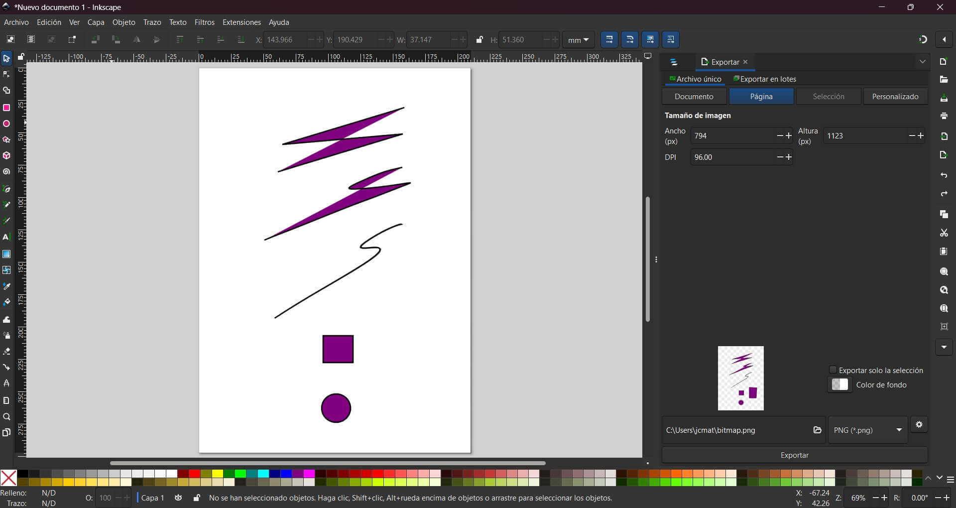
For this week's assignment, I will make a small drawing of my final project idea. The tools that I will be mainly using are the pen tool, rectangle tool, circle tool, and the fill tool, since I feel they are most beginner-friendly.3.2 Line art
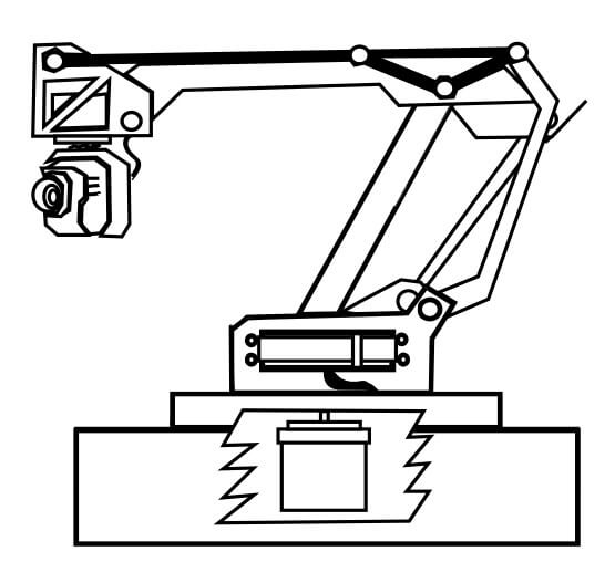
The first step in a digital drawing is to draw the lines and curves that define the shape of the object. I used the pen and rectangle tool to create the line art of the robot arm, adding circles to represent the bores intended for joints. I also used the fill tool to color the different parts of the robot arm.
It is worth noting that, as a beginner in digital art, I often forget to use the layers tool, which is a tool that allows me to separate the different parts of the drawing into different layers, making it easier to modify and color the different parts of the drawing. This is a mistake I made in this drawing that I will try to avoid in the future.
After noticing said mistake, I used the layers tool, located at the top left corner of the screen, to separate a few sections of the robot arm into a layer below the main one.
3.3 Color
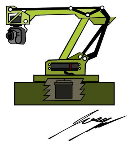
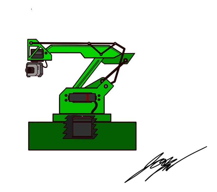
When the line art is finished we can proceed to coloring. For this I used the fill tool to color the different parts of the arm, using the color palette to select a light green and using darker shades of green in an attempt to add a bit of life into the drawing. However, my inexperience in vector graphics is evident, but I hope it serves you as a source of education and amusement.
3.4 Signature
After finishing the drawing, I added my signature using the calygraphy tool in conjunction with the stylus to write my signature in a natural, fluid way. I was pleasantly surprised by the fluidity of the caligraphy tool.
3.5 Export
When I felt like everything was finished, I exported the drawing as a .svg file.
4. Krita
As you can see in my about me page, I am a bit of an artist, with pencil drawing being one of my hobbies, additionally having got started in digital art just before this semester started, with Krita being my software of choice.
Krita is a free, open source raster graphics editor designed for digital artists, supporting fields of painting such as illustrations, concept art, matte painting, textures, comics and animations. Krita includes support for multiple brush engines, layer styles, and blending modes. It also has a user-friendly interface that makes it easy to use, which I appreciated as a beginner in digital art.
For this week's assignment, I recreated the same sketch that I made in Inkscape, but, additionally I used Krita to create a rasterized image of the character I designed for a school project, which you can find in the Project B section of my about me page. This second drawing was an attempt to improve my digital art skills and to experiment with the different tools that Krita has to offer, and I have to say, I actually had a blast in doing so.
Let's take a look at the process I followed for both drawings, starting with the latter:
4.1 New project, UI and tools
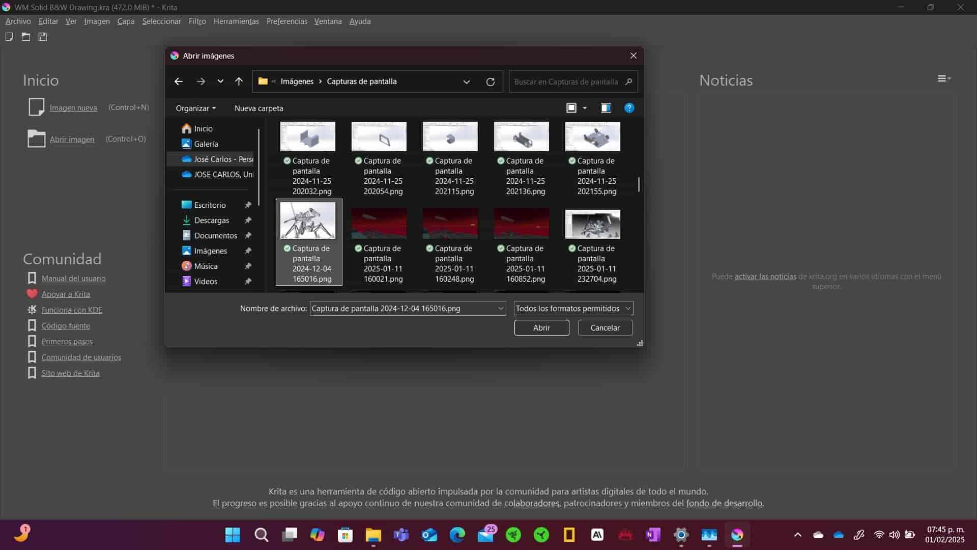
Since I want to use a screenshot of my 3D model as a reference, I start Krita and select the Open Image option, which allows me to open the image of my character's model that I made in SolidWorks.
Let's take a look at the UI and the tools that I will be using for this drawing. The UI is very similar to other raster graphics editors, with the tools being located on the left side of the screen, the properties of the tools being located on the top of the screen and our layers and brushes on the right side of the screen. Usually the color wheel is also located on the right side, but since I use my stylus's buttons to open the color wheel, I have it hidden.
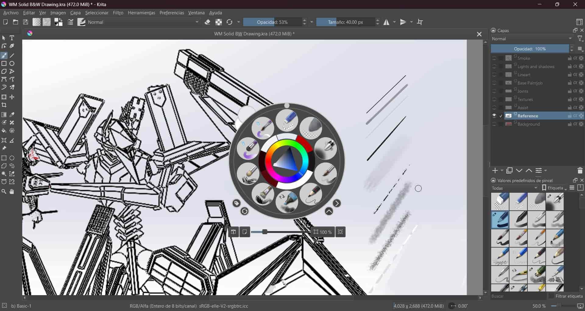
My graphic tablet has buttons and a dial that I use to control the size of the brush and the zoom of the canvas respectively, I also use my stylus's buttons to open the color wheel, brush settings or activate my eraser.4.2 Line art

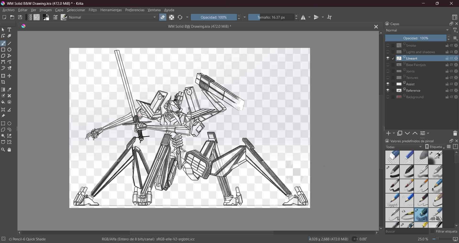
First, I reduce the opacity of the image of my 3D model that I'm using as a reference layer. Next, I create a new line art layer and start using the straight line tool with the Ink-2 Fineliner brush and 5 pixels size to draw the lines, following the reference. I use the eraser tool to correct any mistakes that I make.
It occurred to me that I could use another layer to assist me with any lines that are cut but continue at a further point, this way I can draw the line in the first layer and then use the assist layer to draw a reference of the continuation of the line and finally draw the line at the point where it would continue on the line art layer.
I avoid drawing the joints of the character, this is because in order to get the 3D model to assemble correctly and maintain poseability, I had to make the joints a simple, spherical shape. This helps in a practical sense, but it is not very visually appealing, so I avoid drawing them in the line art.
It is a common practice for digital artists to use different line sizes for different parts of the drawing, for example, using a thicker line for the outline of the character and a thinner line for the details of the character. This is something that I have little experience with, so I avoid it in this drawing.4.3 Joints
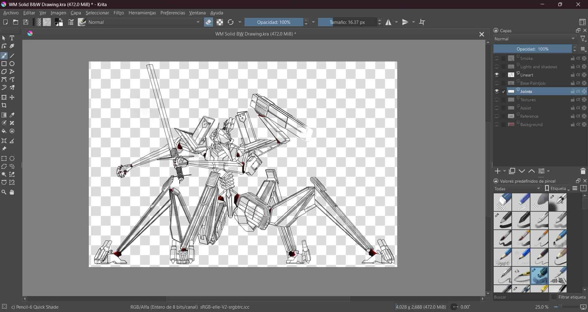
I create a new layer for the joints. To draw them, I use the hand drawn brush tool and the Fineliner brush, I draw a series of curves to represent an organic tissue that connects the different parts of the character, using different shades of red and adding black and white to simulate shadows and highlights.
4.4 Color
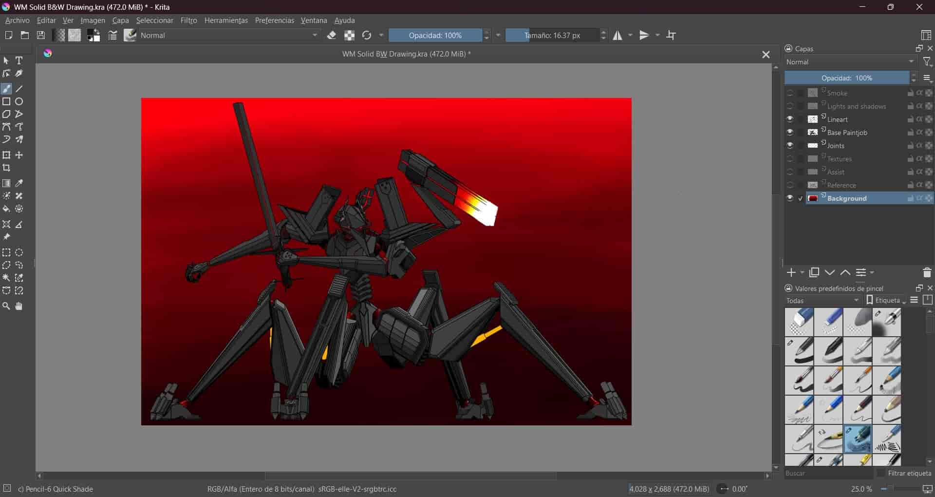
I create a new, base paintjob layer for the main colors, using the hand drawn brush tool and the same Fineliner brush to fill the different parts of the character. I start with a #333333 gray color, slightly changing the shade in different sections to indicate where I will add lights and shadows later. I also draw red highlights in different sections to add more detail. Finally, I color one of my character armaments, a rectangular device mounted on a robotic arm. I wanted to represent a recent firing of the weapon, so I used a Basic-5 Opacity brush and an array of colors, starting from white to yellow, orange, red and finally gray, to represent the heat and energy of the discharge. I also changed the line art from black to white, to further emphasize the energy of the discharge.

4.5 Textures
I create a new layer to add a rough, metalic texture to some parts. Drawing metalic textures is quite an ordeal, and frankly, outside my capabilities as a beginner, so I go on the internet and download a metal brush pack which I will link at the bottom of this page. I then experiment with the different brushes, sizes and shades of gray, combining them to add texture to the drawing, focusing on the darker areas.
4.6 Background
At this point I realize that the drawing is missing something, so I create a new layer for the background. I use the Basic-5 Opacity brush to draw a simple, abstract background, using different shades of red. Starting from a dark red at the bottom and transitioning to a light red at the top.
-
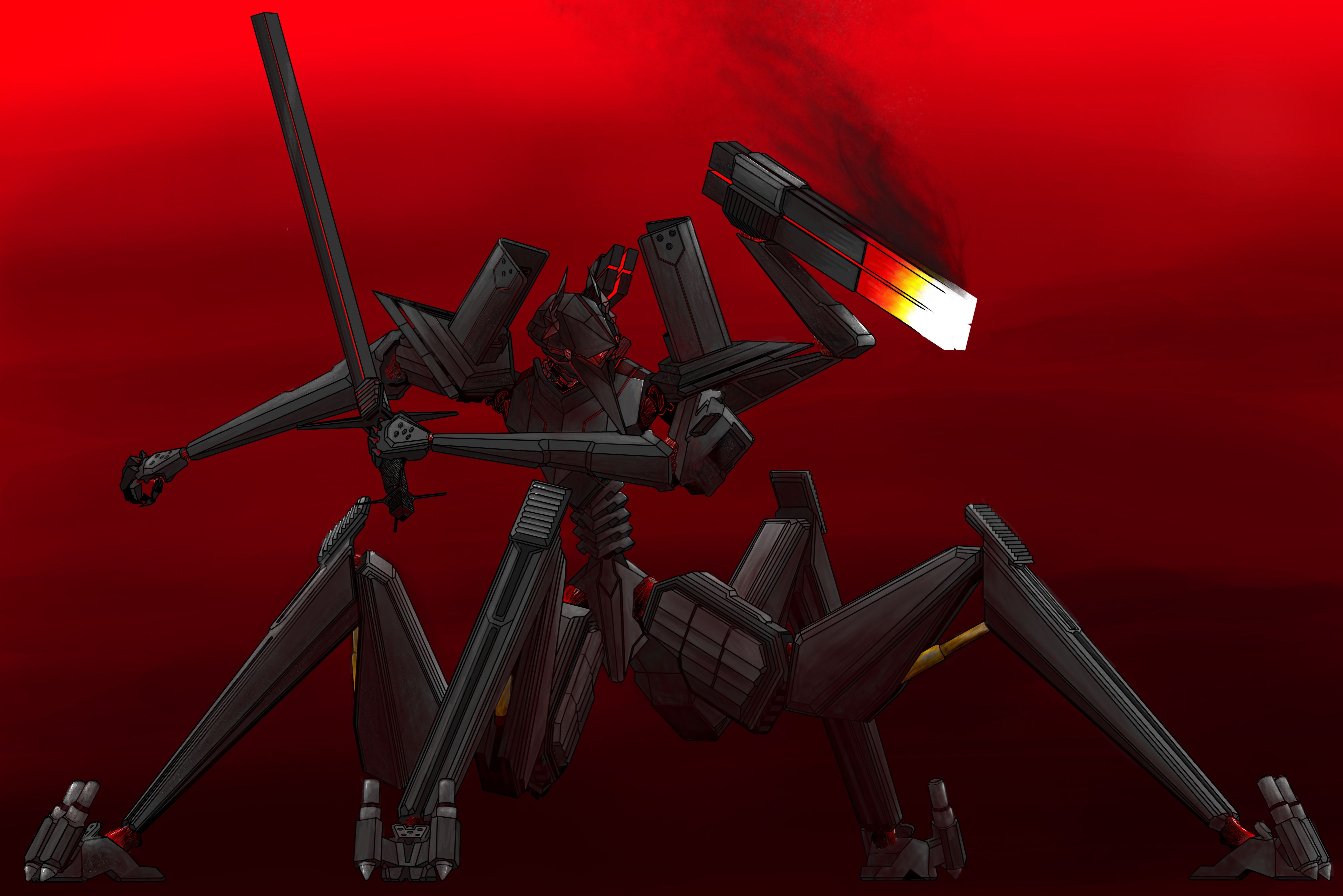
4.7 Lights and shadows
After finishing the background, I create a new layer for the lights and shadows. I use the Airbrush brush to add lights and shadows to the different parts of the character, using the darkest shade of red in the background for the shadows and the lightest shade of gray from the character for the parts that are exposed to light. I add tiny white highlights to the parts that are exposed to the most light. Finally, I add dark gray shadows to the darkest parts.
Lights and shadows are probably one of the hardest things to get right in a drawing, but I have to say, I was rather satisfied with the results.
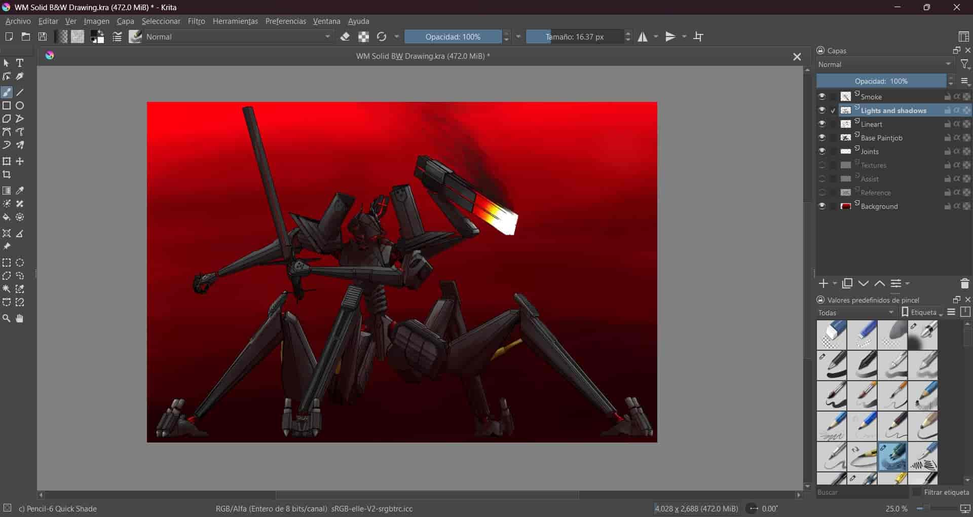
4.8 Smoke
Finally, I create a new layer for the smoke. I use the Basic-5 Opacity and the Texture Big brushes to draw a simple smoke effect, using different shades of gray and white. I also use the smudge tool to blend the different shades together, trying to get a more realistic smoke effect.
Like metal, smoke is a very difficult thing to draw, being a very fluid and dynamic substance, and the results were not as good as I would have liked, but satisfying nonetheless.Here are the final results:
4.9 Export
After finishing the drawing, I save it as a krita drawing file and export it as a .jpeg image. Krita files are saved as .kra files, which are a type of file that saves the different layers, brushes, colors and other properties of the drawing, allowing us to modify the drawing at a later date. The downside is that they can get quite large, with this exact drawing being 35.8 MB in size.
4.10 Final project drawing.
Prepare to be slightly underwhelmed, as I present to you a replica of my Inkscape drawing, now done in Krita. This drawing involved the same line art, color and signature as the Inkscape drawing, but with a few differences, such as the use of different brushes and colors. I also tried to make a better use of the layers tool.
I made this drawing to compare the two software, and this is the conclusion I came to: I don't like vector graphics. I find them to be too rigid and unatural, and I prefer the fluidity and dynamism of raster graphics. I also find that I have more control over the drawing in Krita, with the different brushes, colors and layers allowing me to create a more detailed and realistic drawing. However, an even more important conclusion that I came to is that I really dislike drawing a functional system in two dimensional, non parametric software, having grown acustomed to the precision and detail that parametric 3D modelling software such as SolidWorks offer, I find that I can't get the same level of technical detail in either Inkscape or Krita. Nevertheless, for artistic purposes, a 2D raster graphics editor like Krita is an amazing tool.
5. 3D Graphics
3D CAD software is a type of software designed to assist us in the creation, modification, simulation and analysis of three dimensional parts and systems. CAD software has become one of the most important tools of modern industry, allowing us to acurately simulate a perfect representation of any 3D object that we design.
The CAD software that I have experience with, OnShape, Catia and SolidWorks, are parametric-based software, which means that they use mathematical and geometric parameters to define the dimensions, position, geometry and other properties between the different features of a part or system, allowing us to easily modify the object by changing the parameters.
In my three years of experience, begining in highschool with Onshape, then Catia in my first job and finally SolidWorks in university, I can say without a doubt that SolidWorks is my favorite of the three, with its user-friendly interface, powerful tools and extensive library of features, it is the perfect software for any type of project. This is the software that I will be using for this week's assignment and probably for all other subsequent assignments that require 3D modelling.
For this week's assignment, I will be modeling my final project's parts and assembly, which I will then render and animate.
6. SolidWorks Part Design
A part is a 3D object that we can design through the addition and substraction of material. We usually use a 2D sketch as a template for what the feature operation will extrude along a determined direction.
6.1 New project, UI and tools
We start SolidWorks and create a new project, selecting the part type of document. When we create the part, we are welcomed by the UI, which might appear overwhelming, but we'll soon find to be quite intuitive. At the left of our screen we have the Feature manager tree, here we can find the front, side and top planes and all of the sketches and features that we add to our part. The Command Manager bar, located at the top of the screen, is where we will find our workbenches and tools. Each workbench has a specific function and set of tools, and right below these workbenches we can see our visualization tools, which allow us to orientate our camera in the 3D space, zoom in an out, assign materials and colors, among other visual properties.
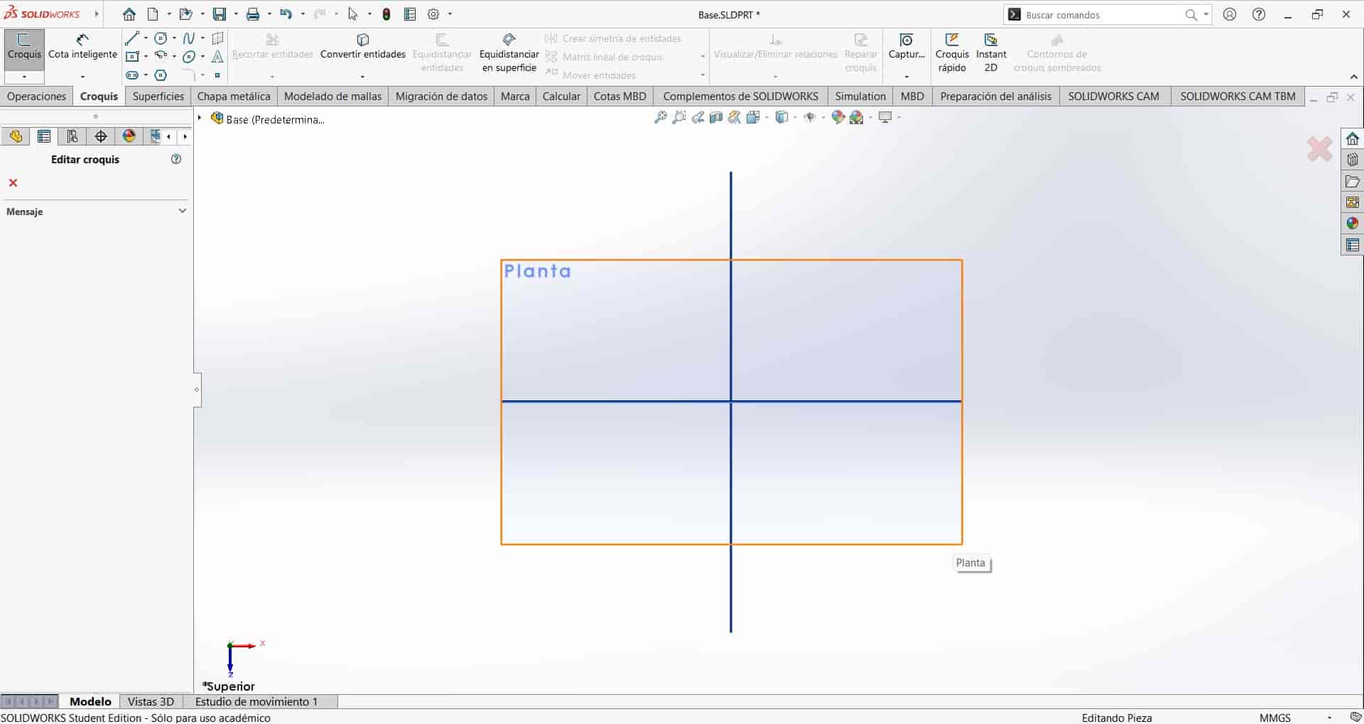
6.2 Sketching
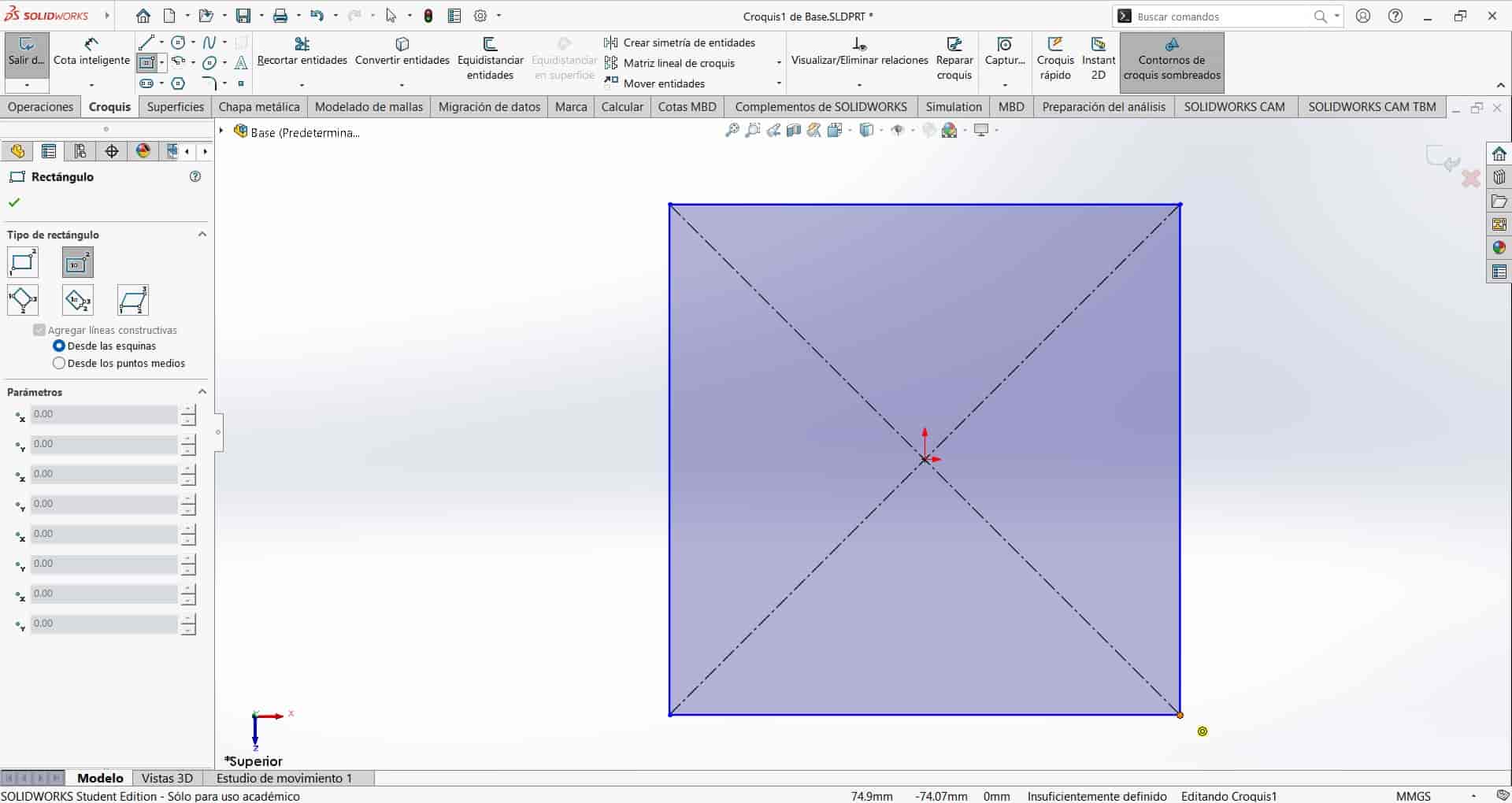
To design our part, we first have to create a sketch. A sketch is a 2D representation of the part that we are designing, and it is made up of lines, curves and other geometric shapes. We can create a sketch on any of the planes that we have available, and we can use the different tools to create the different features of the part. In this case, I will be creating a sketch of the base of the robot arm, which is a simple, rectangular shape.
We position ourselves in the sketch workbench and select the top plane to create our sketch. We then use the center rectangle tool to draw a square, starting from the origin of the plane and dragging the mouse to any point of our screen.
After drawing our shape, we have to assign dimensions and relations to the different features of the sketch. Dimensions are the numerical values that define the size of the different features, such as the length of a line or the radius of a circle. Relations are the geometric properties that define the position of the different features, such as the distance and angle between two lines or if they are equal, perpendicular or parallel to each other.
For this square, we are going to assign a 150 mm length to one of the sides, and make the one of the perpendicular sides equal to the first one, giving us a perfectly defined 150 mm x 150 mm square.
6.3 Features-Extrusion
To transform our 2D sketch into a three dimensional object, we have to subject the sketch to a feature that will give volume to our drawn shape. The extrusion tool allows us to pull the sketch in the third dimension, creating a solid object.
We situate ourselves in the features workbench and select the extrusion tool and select the sketch that we want to extrude. We then select the direction in which we want to extrude the sketch, in this case, I will extrude it 3 mm from the middle, which means that the square will be extruded 1.5 mm in each direction.
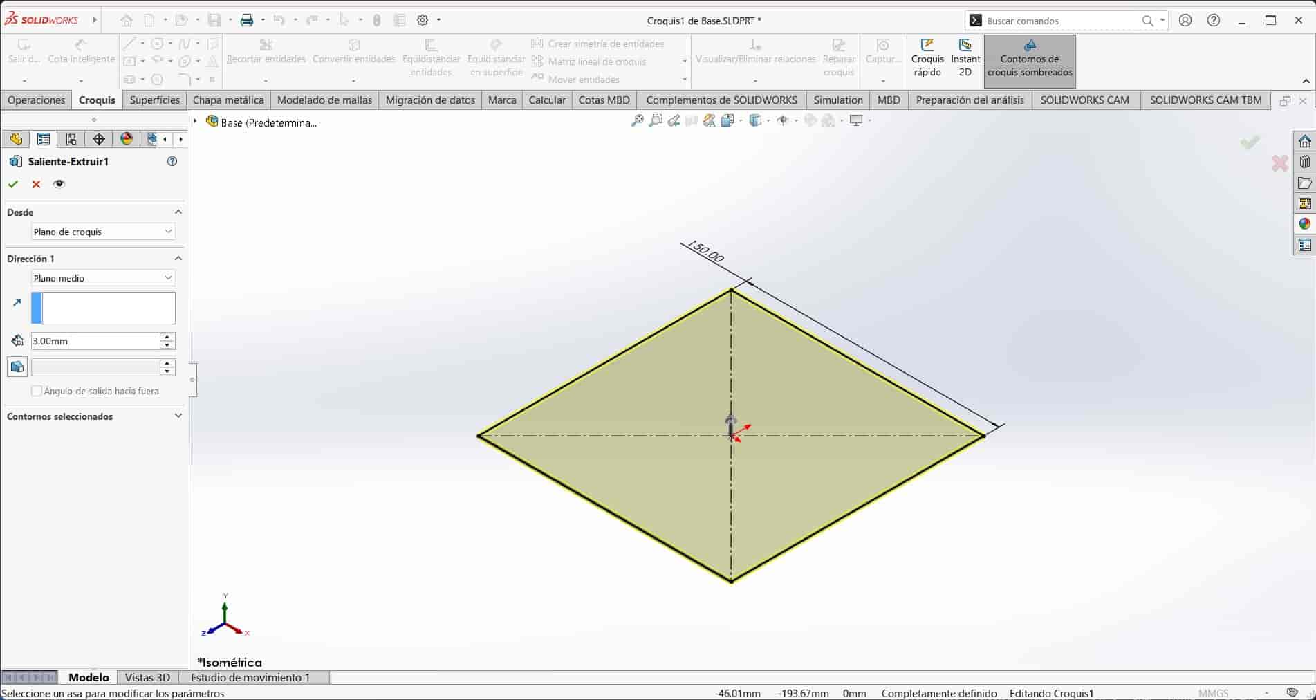
After extruding the sketch, we have a solid object that we can modify and add features to. We can also go back to the sketch and modify it, which will automatically update the solid object.
6.5 Motor holder
I generate another sketch and draw a square with 50 mm sides, I then use the offset tool, which allows me to replicate the selected lines and curves a certain distance inwards or outwards from the originals, to create a bigger square surrounding the first one, with 5 mm of separation.
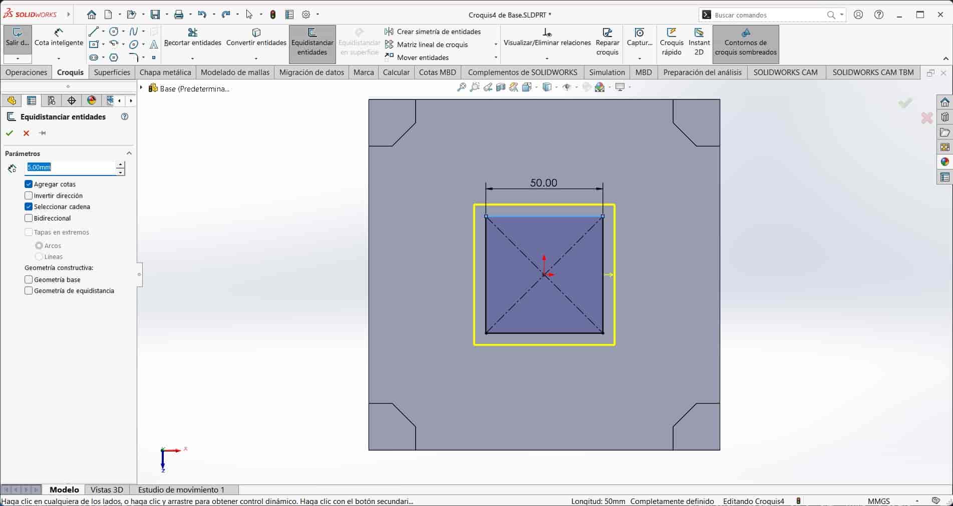
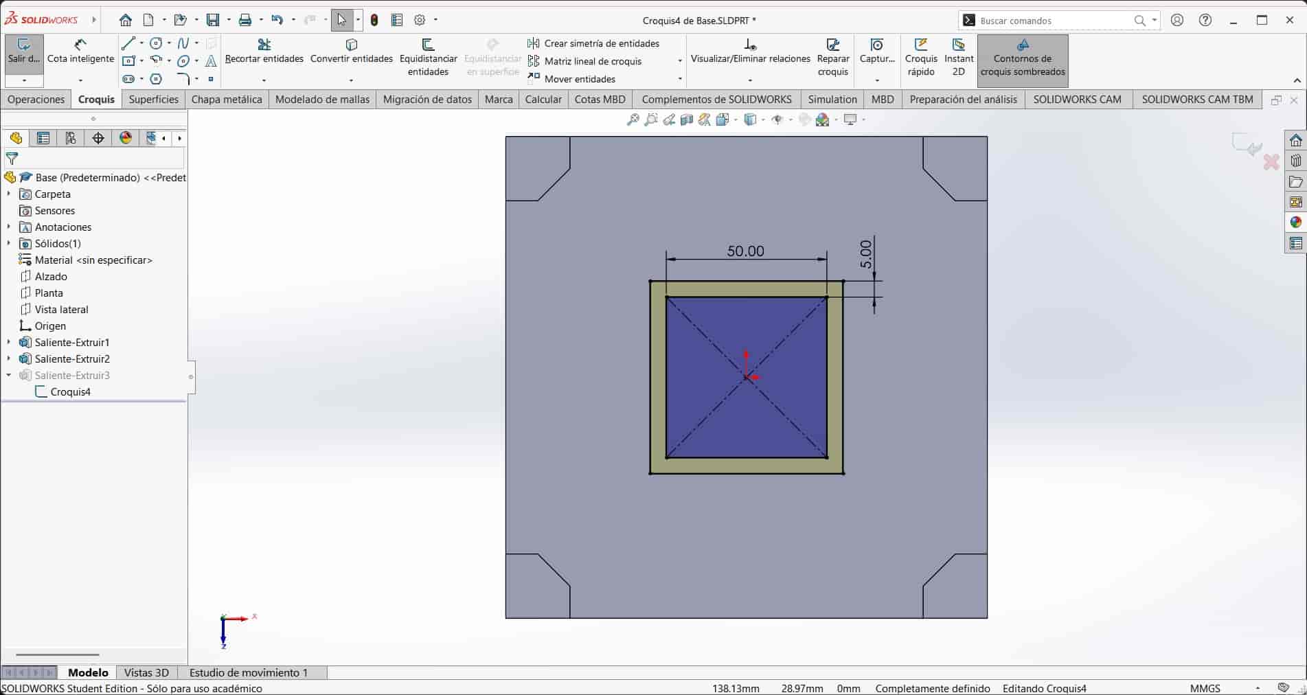
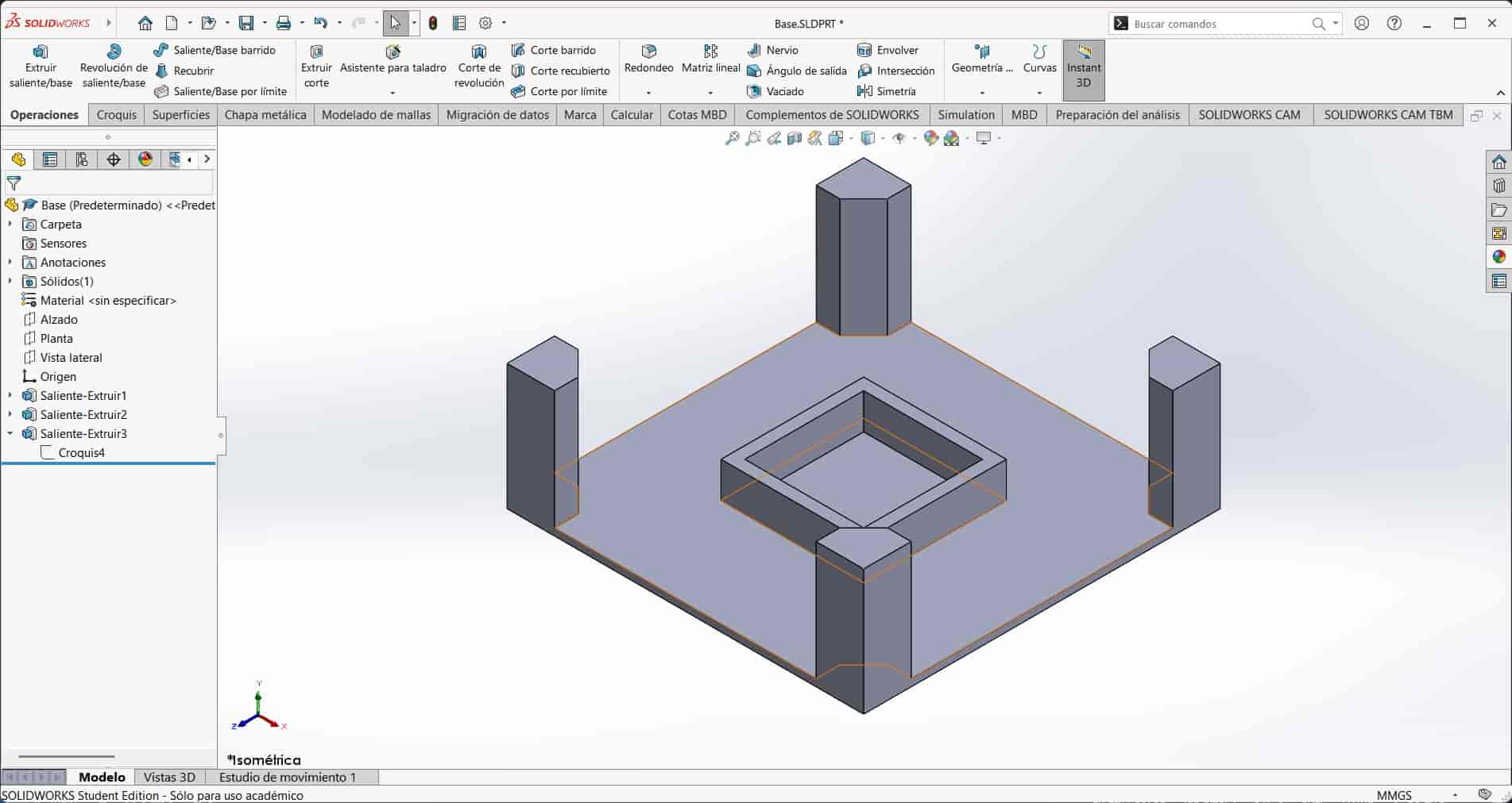
I then extrude this square 15 mm upwards, creating a box intended to hold a stepper mottor.
6.6 Features-Extruded Cut
Unfortunetly, I forgot to include a space for the motor's cables to pass through, so I create a new sketch on the back face of the motor holder and draw a rectangle that is 10 mm wide and goes from the top to the bottom of the face.
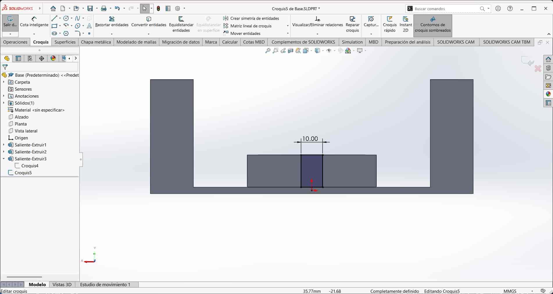
I then use the extruded cut feature to eliminate material from the holder. I select the sketch and the up to next option in the direction section.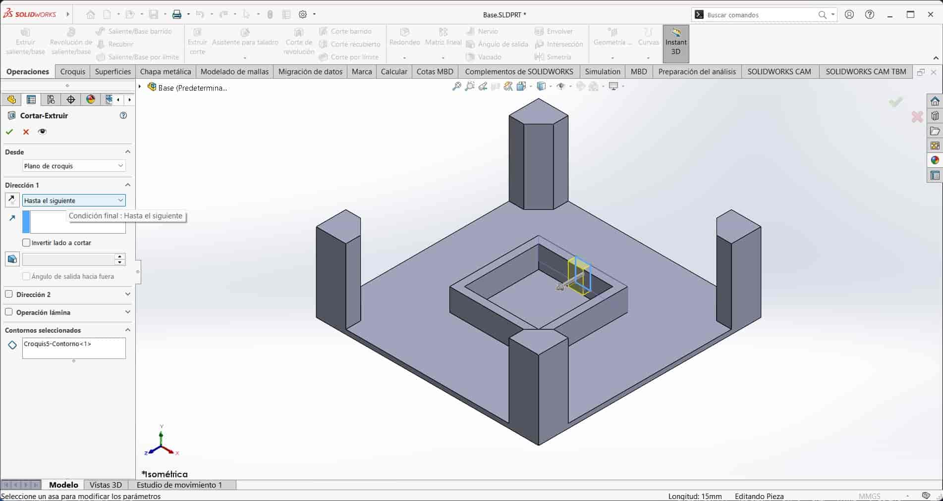
6.7 Features-Fillet
To eliminate stress points in the corners where perpendicular faces meet, I use the fillet tool to create an arch that joins said faces. I select the fillet feature and choose the face-to-face option, I then select the faces of the column in blue and the face of the base in pink, I also input the radius of the arch, in this case, 5 mm.
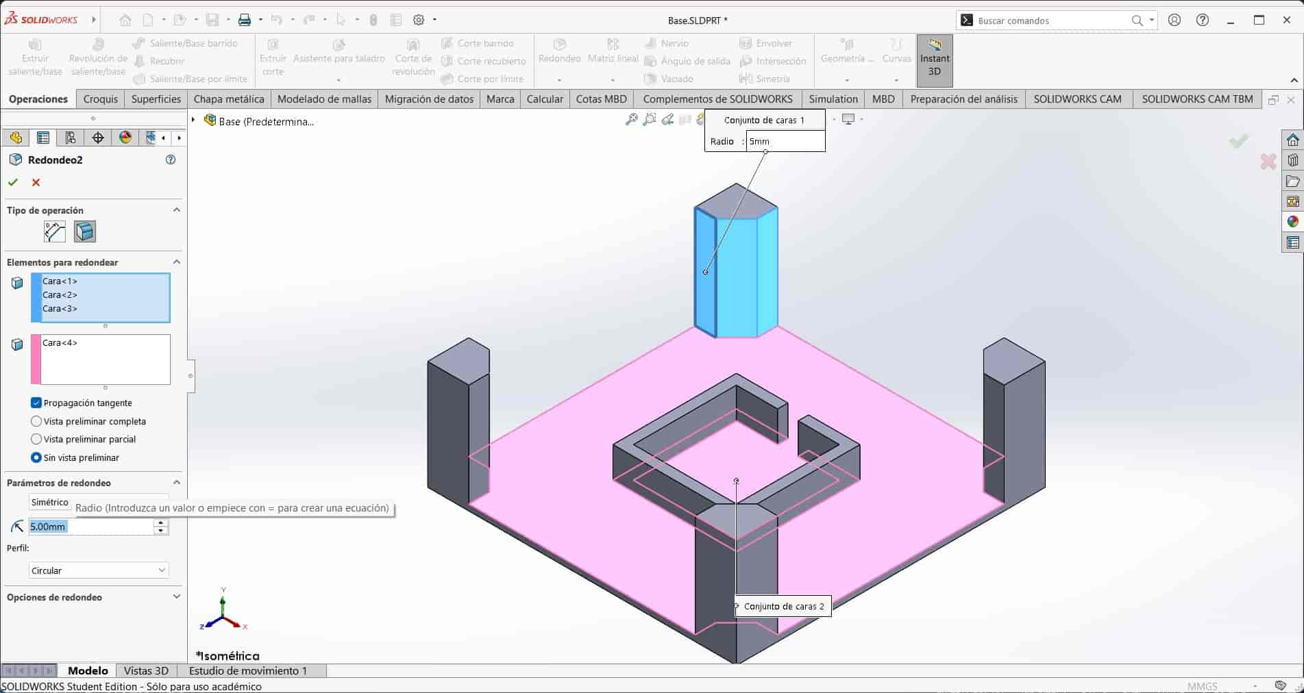 I repeat the process with the other perpendicular corners in the base.
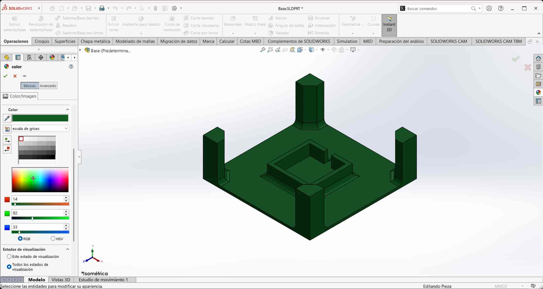
6.8 Color
Once finished with the modeling, I use the appearance tool to assign a color to the part. Since I am planning to use my 3D printer to make the part and my fillament is green, I will paint my non moving parts dark green.
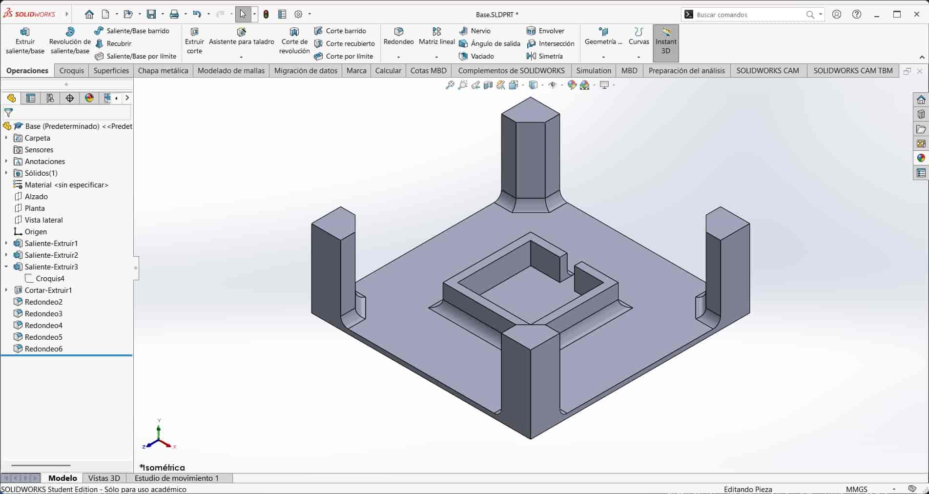
6.9 Conclusion
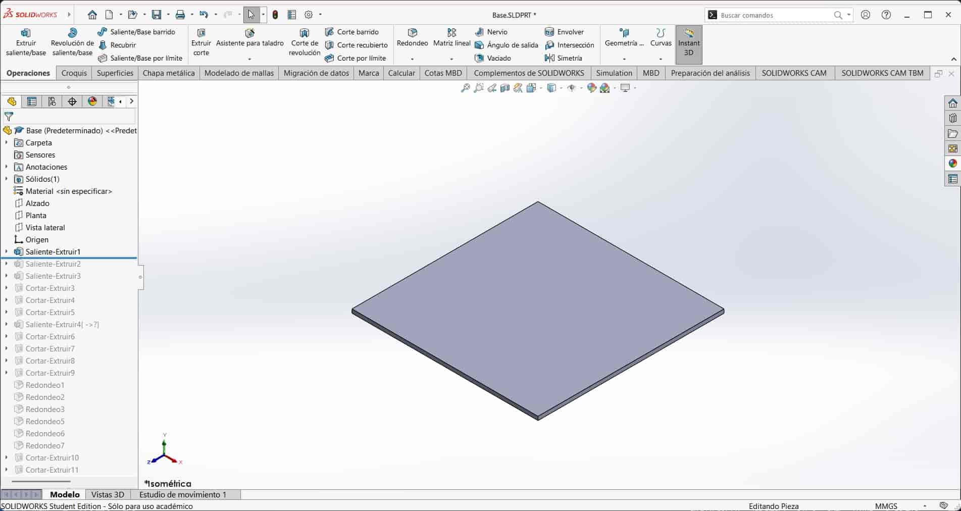
This part is of an extremely simple design, but it serves to demonstrate the essential tools and features of part design, in which we add and substract material any number of times through a variety of feature operations, until we get to the desired shape.
By following this process, I designed other parts that will be used in the final project, I will not go through the process of designing them, but I will show you the final assembly.
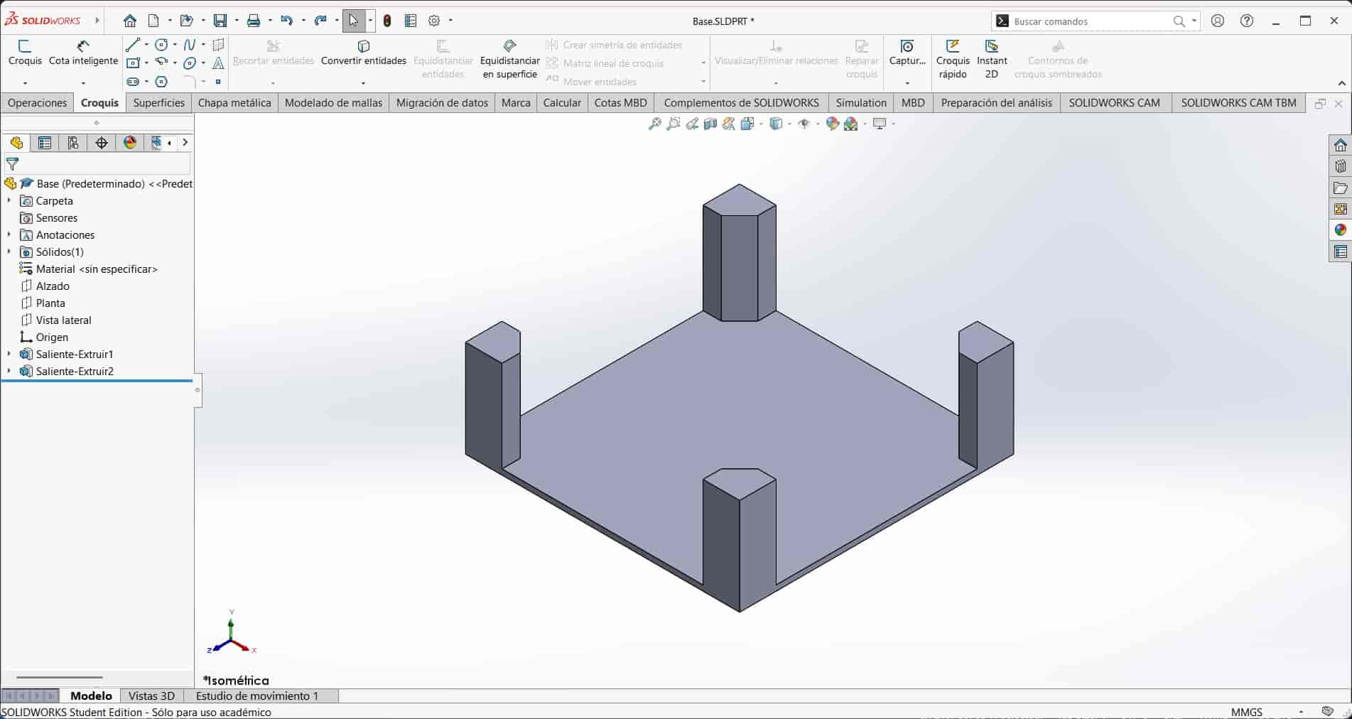
6.4 Columns
We select the top face of the extruded square and start a new sketch. In this sketch I will be drawing the columns that will support everything on top of the base.
I draw a square that is cut in a 45 degree angle at the top right corner, dimensioning it to be 20 by 20 mm, with the cut at 10mm. I then use one of my favorite tools, the symetry tool, to automatically draw the column on the opposite side of the base. To use this tool, I first draw an infinite construction line that goes through the center of the base, construction lines are lines that are not taken into account when creating solid features, but are still useful for establishing geometrical constraints or when using tools such as this one. I select the symetry tool and the two lines that I want to be replicated. After selecting the axis of symetry, the tool will automatically draw the lines on the other side of the axis.
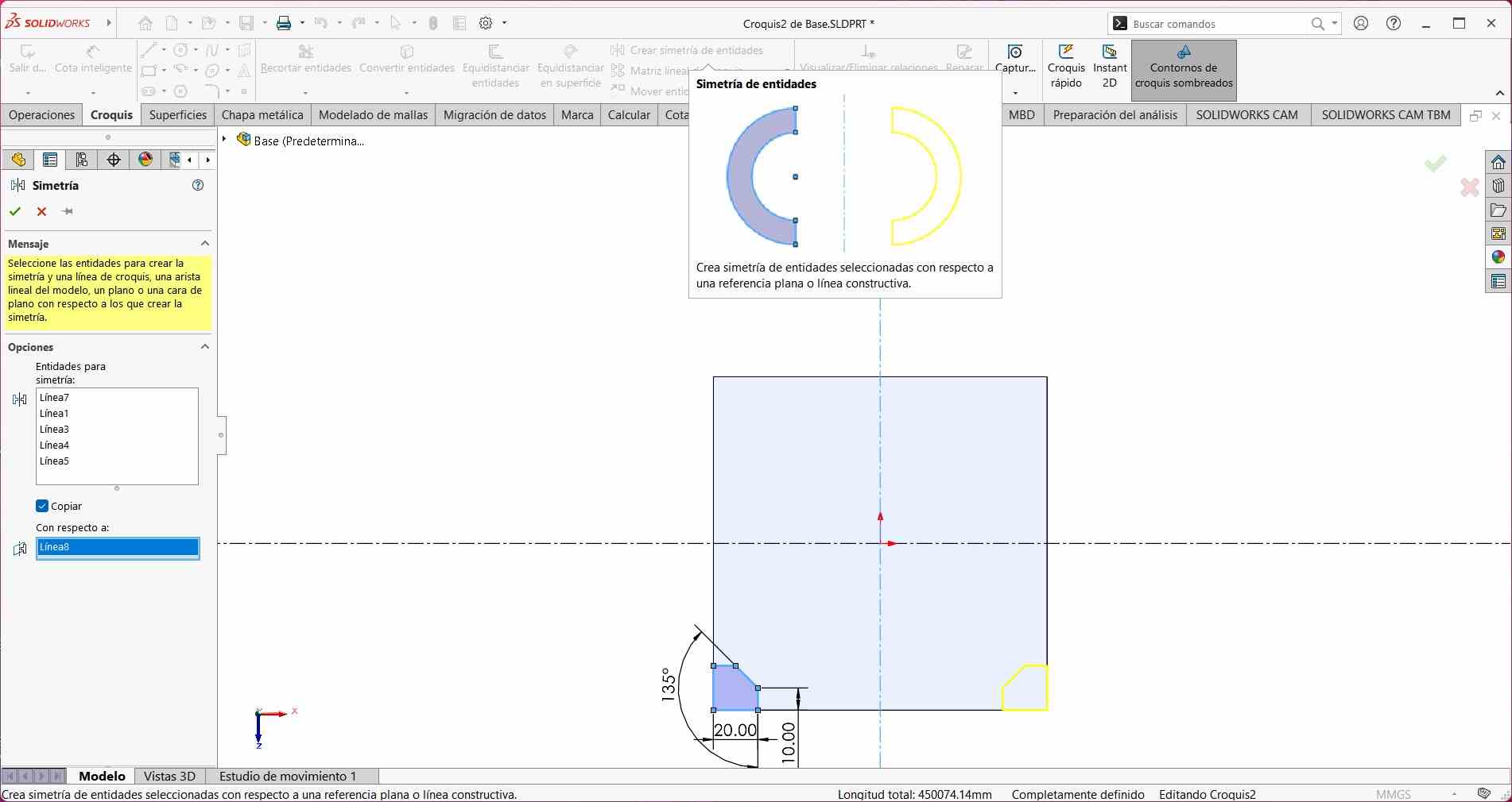
I repeat this proces with a perpendicular symetry axis, giving us the four columns.
After finishing the sketch, I extrude the sketch 50 mm in an upwards direction, giving us the columns.
7. SolidWorks Assembly Design
An assembly is a type of document that allows us to design a system comprised of multiple individual parts.
7.1 New project, UI and tools
When we start a new, assembly type of document, we can see that the UI is virtually the same as in part design, only with the addition of the assembly workbench, where we will find the tools necessary to manipulate and assemble the individual parts.
7.2 Inserting parts
To create an assembly, we have to insert the different parts that we have created into the assembly. We do this by selecting the insert part tool and selecting the part that we want to insert.
After inserting the part, we can move it around and rotate it to the desired position.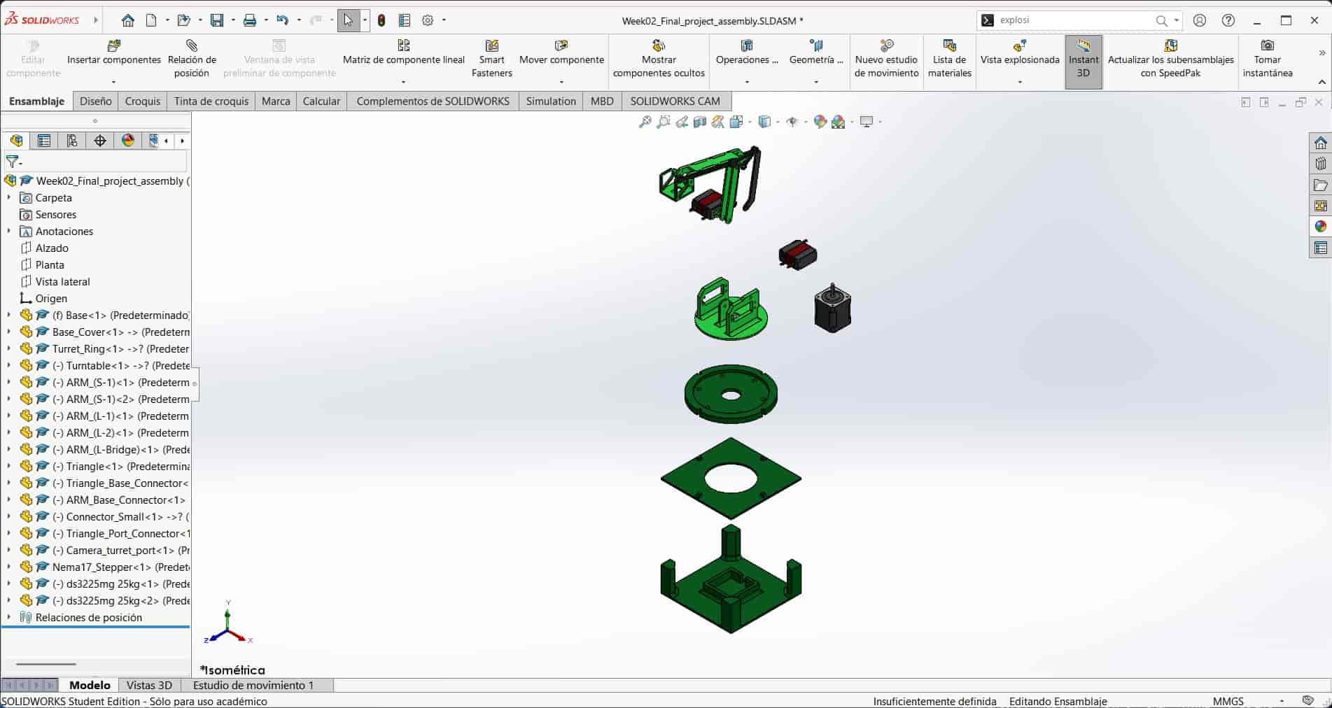
It is worth mentioning that two of the parts that I inserted into the assembly weren't designed by me, but were downloaded from the GrabCAD public library, these being the servo and stepper motors. This library hosts thousands 3D models of different parts and systems, and is a great resource for when we need a part that we don't have the time or the skill to design. I will link the models that I used at the bottom of this page.7.3 Constraining the Assembly
To assemble the different parts, we have to mate them together through geometric constraints. These constraints define the position and orientation of the different parts in the assembly.
We can mate the different parts by selecting the mate tool and selecting the faces, axes, edges or points and choosing the type of geometric constraint that we want, such as distance, angle, face-to-face contact, parallelism, perpendicularity, concentricity, etc.
Let's set an example with this servo, I mate the faces of the servo and the Turntable part as ilustrated in the image below.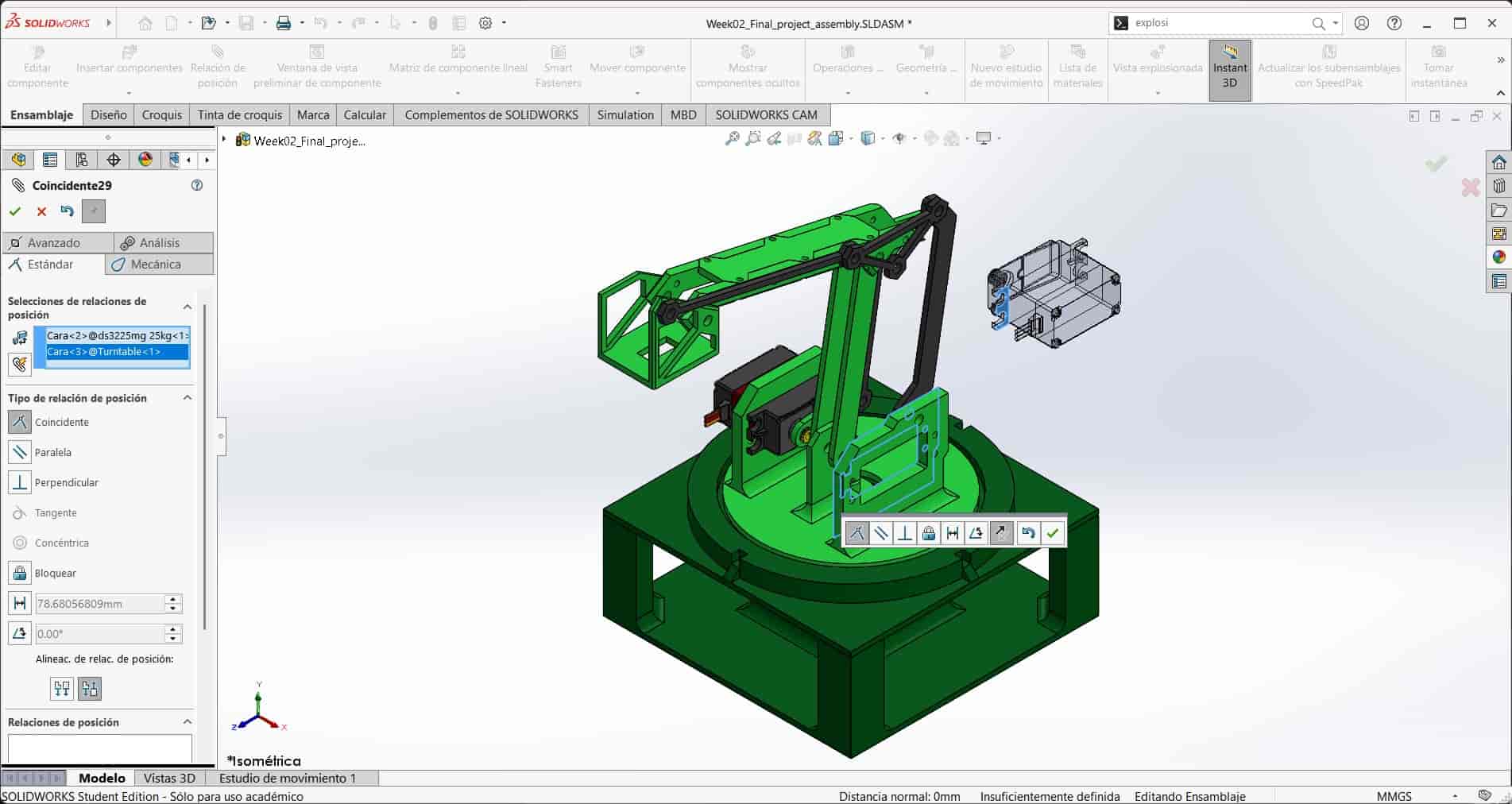
Then I make the axes of the servo and the Turntable concentric, as shown below.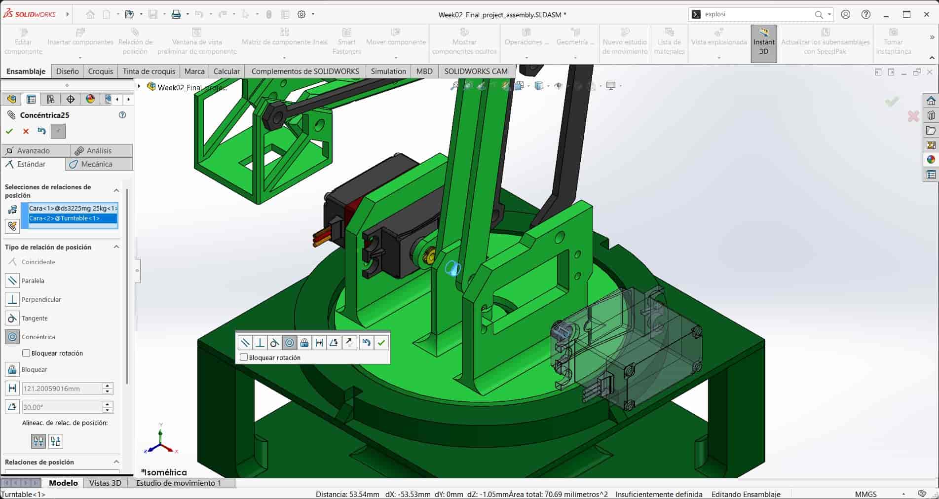
Finally, I set the selected faces to be parallel, making our servo fully constrained.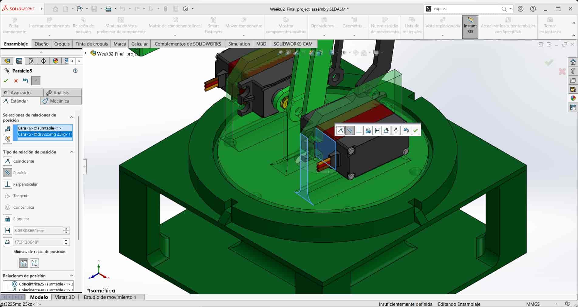
It is by repeating this process with the other parts that we can fully assemble the system, but, I made sure to leave some moving parts unconstrained, as I will be animating them later.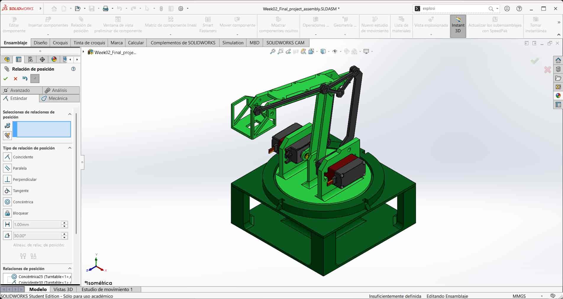
Here is an interactive view of the assembly:
8. SolidWorks Animation
An animation is a series of frames that are played in sequence to create the illusion of movement. In SolidWorks, we can create animations of our assemblies by using the motion study tool, which allows us to animate the different parts of the assembly by inserting various motor functions into it.
8.1 Motion Study Tool
To create an animation, we have to create a new motion study. We do this by selecting the motion study tool at the bottom left corner of the screen and creating a new motion study. Now, I am not very familiar with this tool, but I know how to use it to create a simple animation by giving linear and rotational movement to different parts of our assembly.
8.2 Rotary Motor One
To animate the rotation of the turret, I create a new rotary motor function, this function is located top middle of the motion study menu. I then select the top face of the turntable part as the component that I want to turn and the turret ring part as the component that I want to use as reference for the direction, this can be appreciated in the image bellow, where the light blue and dark blue colors represent each respective part.
I then input the speed and direction of the motor, in this case, 1.5 revolutions per minute, counterclockwise, since slower animations are usually more stable.
I extend the duration of the motor to 5 seconds, which will be the entire duration of the animation.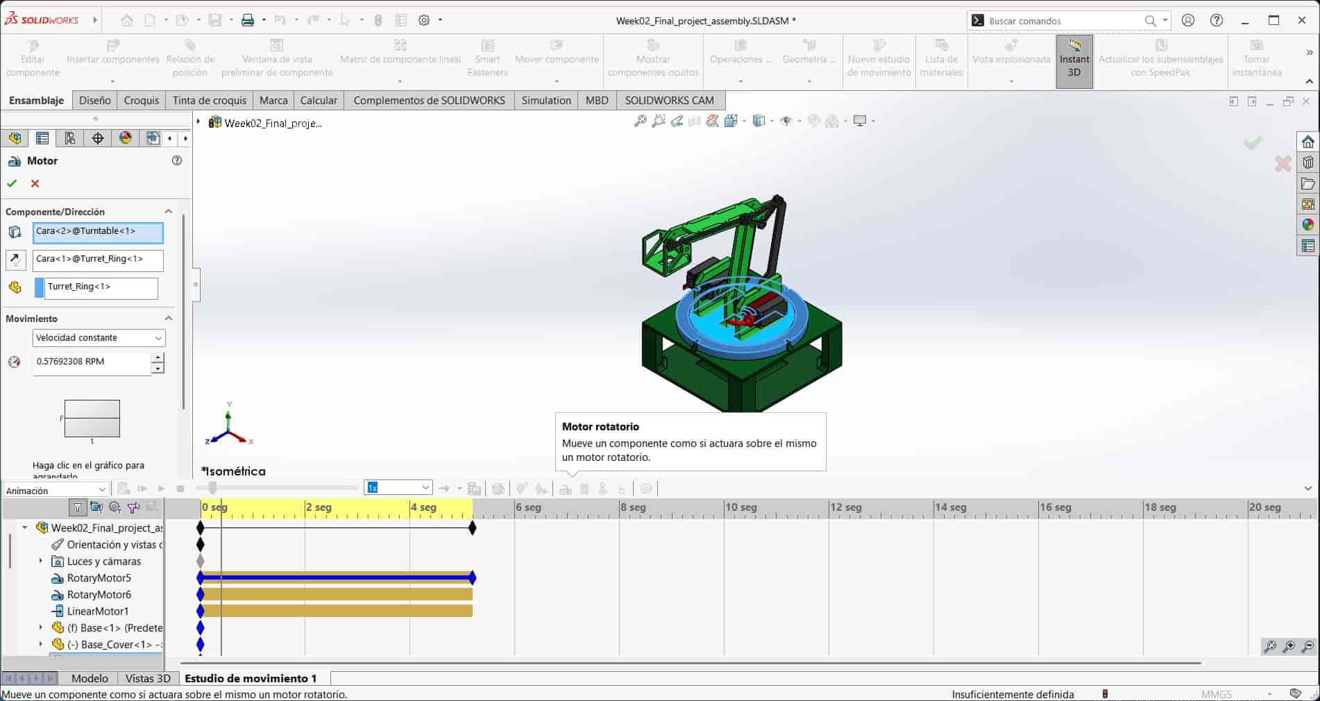
8.3 Rotary Motor Two
To animate the arm moving forwards, I create a new rotary motor function, I select the axis in the turntable as my rotational axis and select the ARM_S1 part for the rotating object, I then input the rotation to be 0.5 rpm clockwise, since the arm is moving forwards.
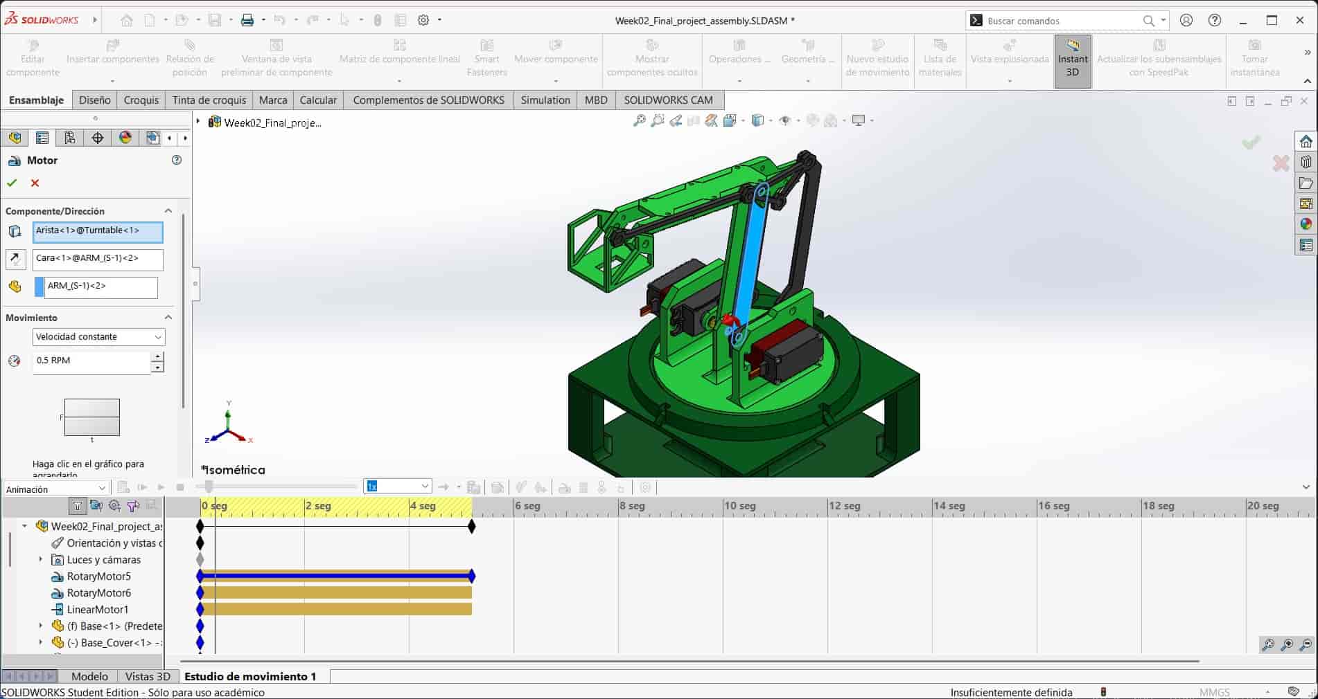
-
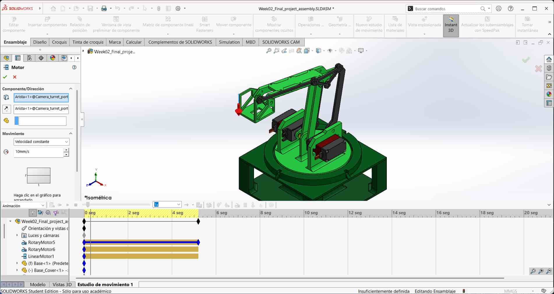
To animate the arm moving down, I generate a linear motor function, this is done with the same tool as the rotary motor, but with the linear option selected. I select a vertical edge of the camera turret port as the object and direction of movement, and input a speed of 10 mm/s downwards.
8.5 Export
8.4 Linear Motor
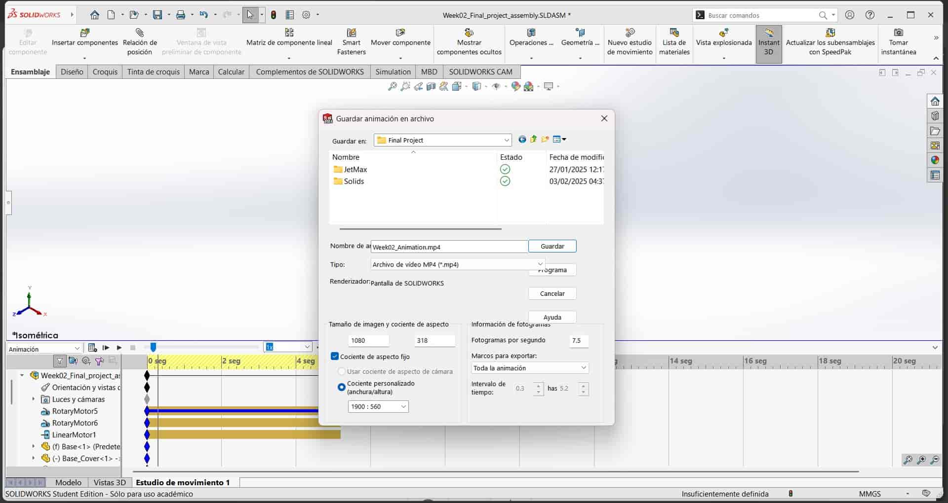
After finishing the animation, I open the save animation menu, located at the top left of the motion study menu, I then change the image size to 1080 and export the animation as an mp4 file.
Here is the full animation of the robot arm:
9. SolidWorks Visualize Rendering
Rendering is the process of generating an enhanced image from a 3D model, we use rendering to make a more visually appealing representation of our model, adding materials, textures, lights and shadows to the model to make it look more realistic.
To render a 3D model, we use a program called a rendering engine, which is a type of software that uses algorithms to calculate the visual properties of the model, and then generates an image based on these calculations.
The rendering engine that I will be using is SolidWorks Visualize, which is a rendering engine that is integrated into SolidWorks, allowing us to render our 3D models directly from the program.
9.1 New Project
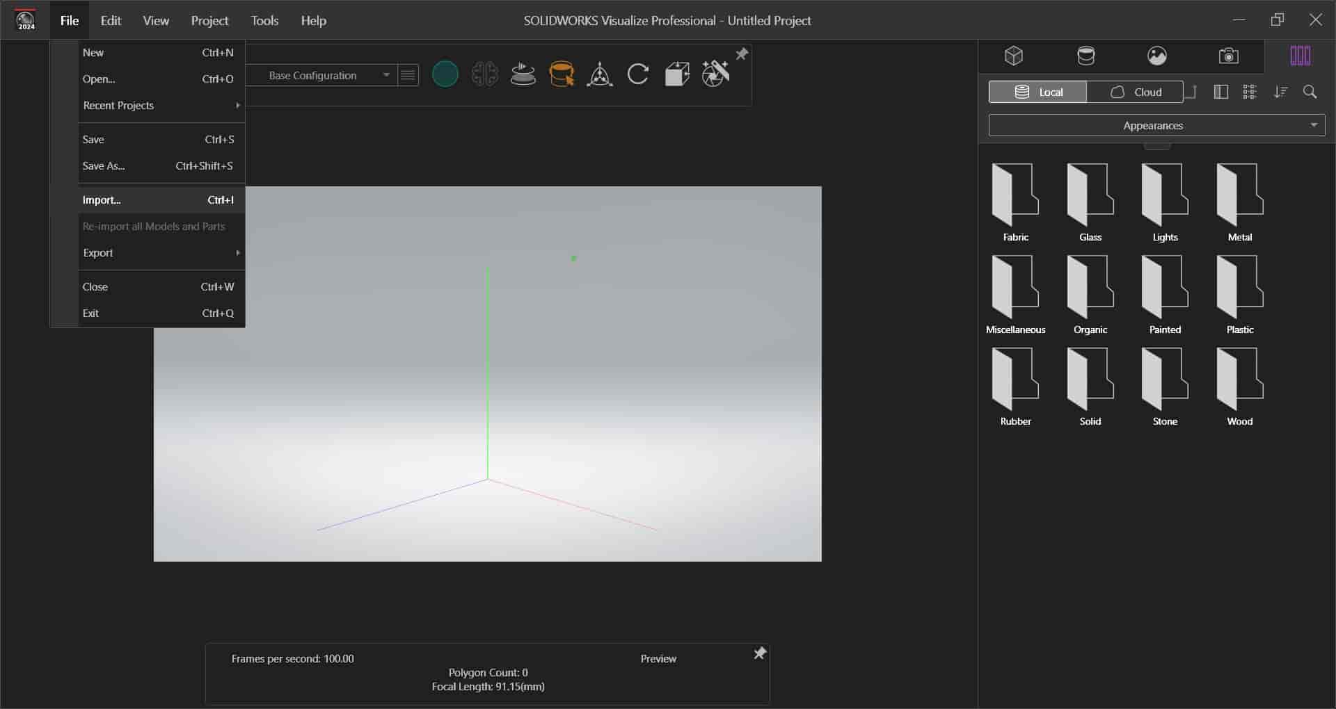
I open a new document and select the Import option in the files menu. I then select our robot arm assembly and import it into the program.
9.2 Appearance Menu
When we click on the imported object, a menu will appear on the right side of the screen, this is the appearance menu, where we can manipulate the visual properties of the object, such as the materials, textures, lights and shadows.
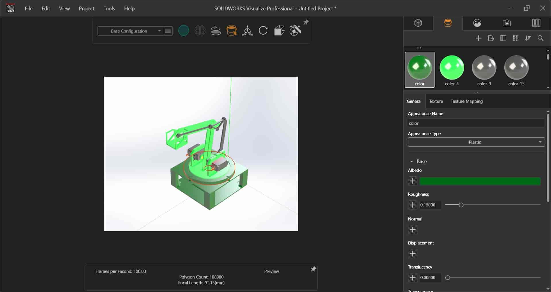
Right off the bat, I select the colors that belong to my plastic parts and change the texture to a completely rough one, since I think they were too shiny as they were.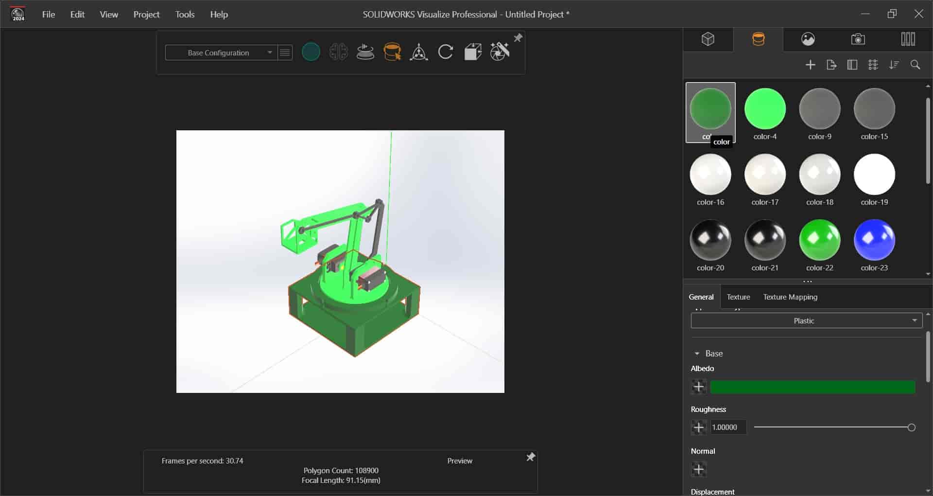
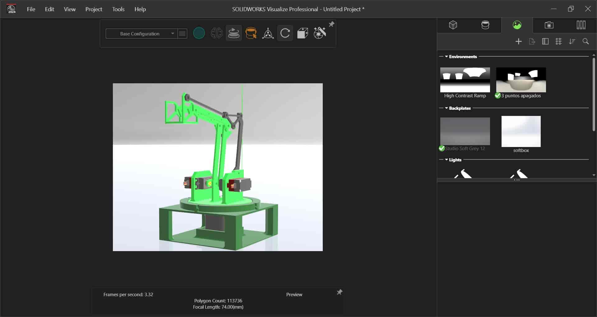
This will be the only change I make in the appearance menu.9.3 Scenes Menu
The scenes menu allows us to change the background of the image, as well as the lighting and the environment of the scene. I select the studio soft grey 12 backplate and change the position of the camera to get a better angle of the arm.
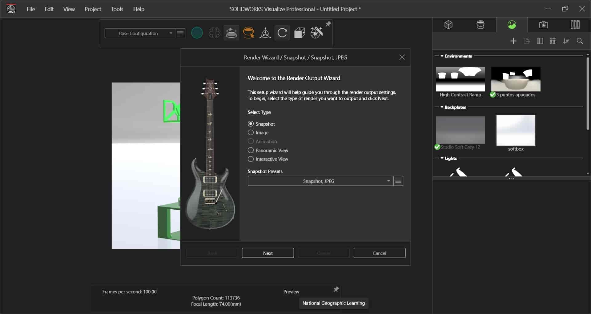
9.4 Render Wizard
When we are finished changing the visual properties of the object, we can render the image by selecting the render wizard tool, displayed with a logo of a camera lens and magic wand located at the top of the screen. We then select the render quality, in this case, I select the snapshot jpeg option, and the folder where I want to store the image.
Here is the final render of the robot arm: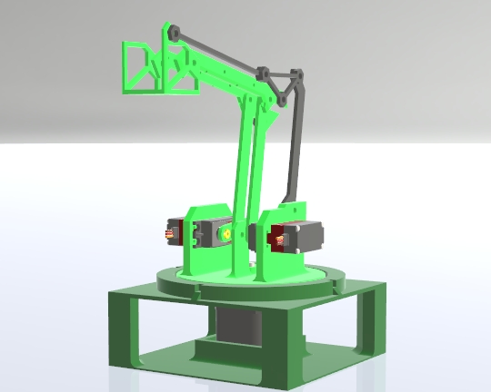
10. Image and Video Compression
As you can see, the documentation process greatly benefits from the use of images and videos, which can help us better understand the different tools and techniques that we use in our projects, as well as appreciate the final results. However, images and videos can be quite large in size, which can make it difficult to store and share them.
For this reason, we use image and video compression techniques to reduce the size of the files, while maintaining the quality of the images and videos. There are many different compression techniques that we can use, such as reducing the resolution of the image, reducing the number of colors in the image, reducing the frame rate of the video, etc.
My local instructors have provided us with a variety of tools for image and video compression, these being TinyPNG and Imagecompressor for images and FFmpeg for videos.
TinyPNG and Imagecompressor are websites that allow us to upload images and compress them, they are very simple and easy to use tools that can greatly reduce the size of our images.
Here is an example of how I used imagecompressor to compress some of the images in this documentation:
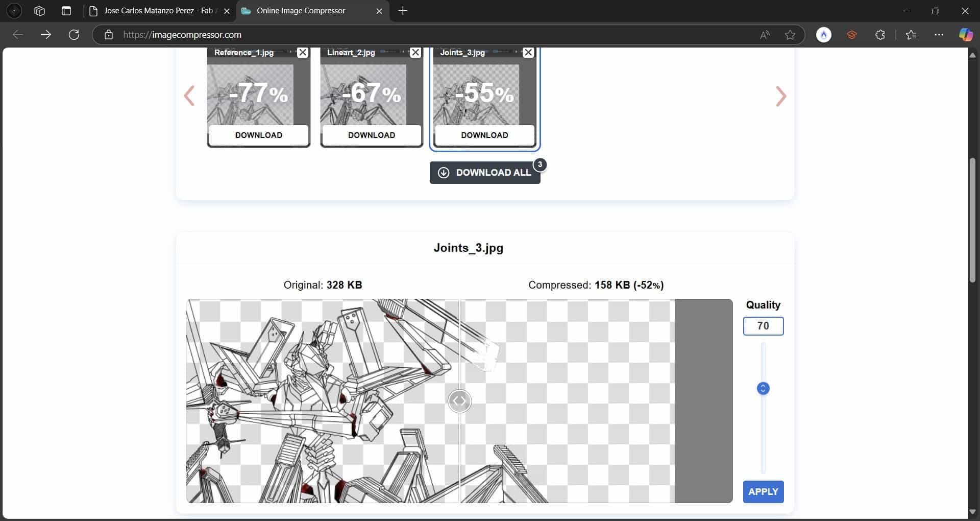 Using this webpage is extremely simple, you can upload the images by dragging them from your file manager, letting you compress up to twenty at a time. After the upload you can individually change the size and qualliity of each image, and then download them all in a zip file.
FFmpeg is a command line tool that allows us to compress videos by reducing the resolution, frame rate, quality, etc. I consider this tool to be more complex than TinyPNG, but it is still a very useful resource for video compression.
To compress smaller videos, such as this week's animation, I use WhatsApp to send files, which automatically compresses the videos that we send through the app, making them easier to share.
Using this webpage is extremely simple, you can upload the images by dragging them from your file manager, letting you compress up to twenty at a time. After the upload you can individually change the size and qualliity of each image, and then download them all in a zip file.
FFmpeg is a command line tool that allows us to compress videos by reducing the resolution, frame rate, quality, etc. I consider this tool to be more complex than TinyPNG, but it is still a very useful resource for video compression.
To compress smaller videos, such as this week's animation, I use WhatsApp to send files, which automatically compresses the videos that we send through the app, making them easier to share.
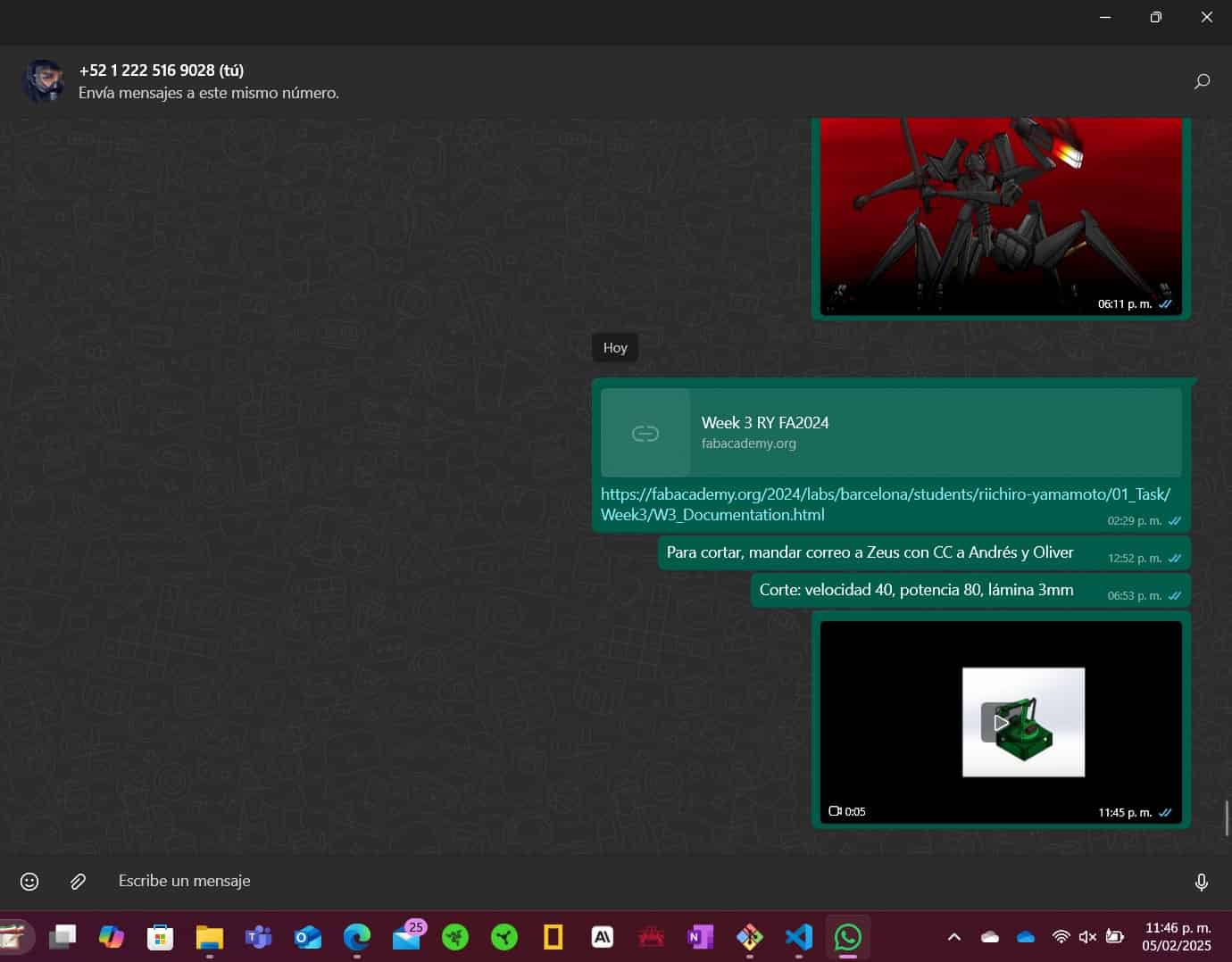 I use WhattsApp to send the video to myself, and then download it to my computer, this way I can compress the video without losing quality.
11. Comments and Recommendations
Both 2D and 3D design software are amazing tools that allow us to express our creativity and ingenuity. Assignments like these are very enjoyable for me, as they allow me to experiment with different tools and techniques while leveraging my strenghts as an artist and engineering student.
A common problem with these sort of files is size, for example, my Krita file was 35.8 MB in size, which is quite large for a simple drawing, and simply cannot be integrated into my repository and my SolidWorks assembly was 1.5 MB in size. This is because these files save all of the different features, tools, colors, materials, textures, lights and shadows that we use in the drawing, which can make the files quite large.
You can find an incredible amount of tools and 3D models online, for example, the metal brush pack that I found on the internet to add texture to my drawing, and the 3D models for the motors in my assembly.
12. Learning Outcomes
The only software that I wasn't familiar with from the get go was Inkscape and vector graphics editors in general, which probably contributed to my immediate dislike of the software.
Even though I had experimented with Kirta before, this was my first full digital drawing, which I am very happy with. I will keep honing my skills in raster graphics editors in the future.
For 3D modelling, I haven't yet experience a better software than SolidWorks, still as user friendly and capable as always, I will probably keep using this software for all of my 3D modelling needs.
Useful links
- Krita Metalic Brushes by Draneria
- GrabCAD DS3218 Servo Motor Model
- GrabCAD NEMA 17 Stepper motor Model
Files
- 2D Vector Robot Arm Drawing
- 2D Raster Robot Arm Drawing
- 3D Models
- Solid Visualize Render
One of the files that I produced for this assignment, my character's 2D Raster's .kra file, has resulted to be too large to be directly integrated into my repository, with a size of 35.8 MB. The solution that I came up with was to host it inside a google drive folder that you can access by clicking here.