09. Input Devices
Summary
Hi! This week was focused in input devices, for this week's assignment we had to add a sensor to a microcontroller board that we had designed and read data from it.
I will be working with my XIAO RP2040 PCB, developed during week 08, and an OpenMV H7 camera as my sensor.
For our group assignment, we had to probe an input device's analog levels and digital signals.
1. Introduction to Input Devices
Input devices are components that collect data from the physical world and convert it into electrical signals that a microcontroller or computer can process, allowing our systems to sense and interact with their surroundings.
Input devices make it possible for a machine to read data from:
- Movement - Position, speed, acceleration.
- Light - Brightness, infrared, color.
- Force & Pressure - Weight, strain, impact.
- Sound & Vibration - Audio signals, environmental noise, mechanical vibrations.
- Proximity & Touch - Contact detection, distance measurement.
- Environmental Changes - Temperature, humidity, gas presence.
From these inputs, our systems can obtain the necessary data to conduct their intended tasks. From my perspective, most systems follow the same process, starting by taking the input data, processing it through code and outputting the results, which can be used in an immense variety of ways depending on the output that we seek.
Once an input device collects data, it needs to send signals to a microcontroller, these signals can be analog, which transmit continuous values and are read using an Analog-to-Digital Coverter, or digital, which transmit ON/OFF states or binary data that are read through GPIO pins, I²C, SPI, or UART.
2. Types of Input Devices
Motion and Position Sensors
- Accelerometers - Detect acceleration and tilt.
- Gyroscopes - Measure rotation and orientation.
- Encoders - Track position and rotation.
Light Sensors
- Photoresistors - Detect ambient light.
- Photodiodes - Detect infrared.
- Color Sensors - Detect RGB color values.
- ToF Sensors - Measure distance using light pulses.
Force, Pressure and Touch Sensors
- Load Cells - Measure weight.
- Force Sensitive Resistors - Detect touch pressure.
- Strain Gauges - Measure structural deformation.
- Piezoelectric Sensors - Detect force and vibration.
Sound and Vibration Sensors
- Microphones - Capture sound waves.
- Piezoelectric Vibration Sensors - Detect mechanical vibration.
Proximity and Contact Sensors
- Ultrasonic Sensors - Measure distance with sound waves.
- Infrared Sensors - Detect motion and heat.
- Capacitive Touch Sensors - Detect touch without physical contact.
- Inductive Sensors - Detect metal objects.
Environmental Sensors
- Temperature Sensors - Detect heat levels.
- Humidity Sensors - Measure moisture levels.
- Gas Sensors - Detect toxic gases like CO₂, CO, methane.
- Barometric Pressure Sensors - Measure air pressure.
3. AI and Computer Vision in Input Devices
Most input devices sense physical forces, but cameras are unique, they process visual data, allowing machines to recognize objects, patterns, and movement. Unlike other sensors that provide purely numerical data, cameras provide detailed images that require advanced processing through computer vision or AI models to extract useful information.
Let's take a look at how these systems complement each other.
3.1 Artificial Inteligence
AI is the field of computer science that develop systems capable of learning, reasoning, and making decisions without our direct control. Instead of following predefined instructions, we train AI systems to analyze data, recognize patterns, and improve over time.
To develop these systems we use two techniques, Machine Learning, where AI is trained with large amounts of data to recognize patterns, and Deep Learning, which uses neural networks inspired by the human brain to analyze complex data, like images and video.
3.2 Computer Vision
Computer vision is a subfield of AI that enables machines to interpret and understand visual data from the real world. It allows computers, robots, and other systems to observe and make decisions based on images or video, just like we do.
What can it do?
- Detect objects and track movement in real time.
- Recognize faces and interpret emotions.
- Read text and translate languages.
- Navigate autonomously.
- Inspect products for defects in manufacturing.
How does it work?
- Image Acquisition - A camera captures an image or video feed, which are typically in RGB, grayscale, or infrared, depending on the use case.
- Preprocessing and Feature Extraction - The image may need filtering, noise reduction, or contrast adjustment for better accuracy. Once the feed is adjusted, the system detects edges, colors, shapes, or textures to identify features in the image.
- Object Detection and Classification - AI models analyze the image to detect objects and classify them based on pre-trained data. The objects are assigned labels like "face," "car," "person," etc. and a confidence score, which determines how certain the model is about the detection, is generated.
- Decision Making and Output - Based on what the system sees, it triggers an action.
4. OpenMV H7 cam
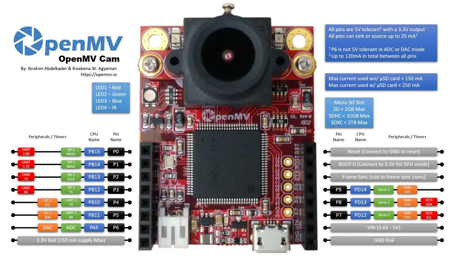
The OpenMV H7 camera is an embedded vision system designed for real-time image processing and AI based object detection in small, low-power applications. It features a powerful processor, multiple camera sensor options, and a variety of connectivity interfaces for integration with microcontrollers and other systems.
Unlike traditional cameras that just capture images, the OpenMV H7 processes visual data on-board, making it perfect for robotics, automation, and small AI applications.

4.1 Technical Specifications
Processor and Performance
- Microcontroller: STM32H743VI (ARM® 32-bit Cortex®-M7 CPU, 480MHz)
- Flash Memory: 2 MB
- RAM: 1 MB
- Double Precision Floating-Point Unit
- Digital Signal Processing
Camera Sensor
- Default Sensor: MT9M114
- Max Resolution: 640x480
- Supported Formats: Grayscale, RGB565, JPEG
- Frame Rate: Up to 60 FPS
- Focal Length: 2.8mm
- Field of View: ~70°
- Infrared Support: Compatible with IR lenses
Image Processing Capabilities
- Edge Detection: Canny, Sobel, etc.
- Template Matching: Object tracking & recognition
- Optical Flow: Motion tracking between frames
- Blob Detection: Finds bright/dark regions in an image
- AI Model Support: TensorFlow Lite, FOMO object detection
- Barcode & QR Code Reading
- AprilTag Recognition: For augmented reality applications
Connectivity & Interfaces
- USB: Micro-USB for programming and data transfer
- UART: 3.3V logic for serial communication with baud rates up to 921600 bps
- I²C: Supports communication with external devices
- SPI: For fast peripheral communication
- GPIOs: 3.3V logic, used for triggers and external control
- MicroSD Card Slot: Supports FAT32 for image storage
Power & Consumption
- Operating Voltage: 3.3V - 5V
- Power Consumption: ~200mA at 3.3V
- Low power mode
Dimensions & Weight
- Size: 45mm x 36mm x 30mm
- Weight: ~17g
4.2 How it works
1. Image Acquisition
The OV7725 CMOS sensor takes images or video in RGB565 or grayscale at different resolutions.
2. Image Processing
The camera applies filters, detects edges, and identifies shapes, it then extracts key features like color, movement, and object position.
3. AI Based Object Detection
Runs pre-trained AI models to detect and classify objects in real time.
4. Communication with other Devices
Sends processed data to microcontrollers using UART, SPI, or I²C, or is able to directly control LEDs, motors, or other components based on detections.
5. My Computer Vision System
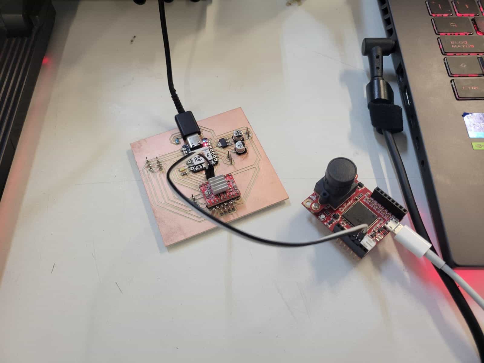
The system that I developed this week was a simple application of computer vision, in which I used the H7 to scan for human facial features, then communicate through UART with the PCB that I fabricated during week 08, to activate the PCB's LED whenever a human is detected.
5.1 XIAO RP2040 Board Code
First, I wrote the code for my XIAO PCB, it's functions are very simple; The XIAO listens for messages over the Serial1 interface, which actively recieves messages from the H7. Based on the message received, the LED turns on or off.
#define LED_PIN D5

void setup() {
    pinMode(LED_PIN, OUTPUT);
    Serial1.begin(115200);
    digitalWrite(LED_PIN, LOW);
}

void loop() {
    if (Serial1.available()) {
        String data = Serial1.readStringUntil('\n');

        if (data == "DETECTED") {
            digitalWrite(LED_PIN, HIGH);
        } else if (data == "NO_PERSON") {
            digitalWrite(LED_PIN, LOW);
        }
    }
}
Once ready, we upload the code into the XIAO.
5.2 OpenMV H7 cam code
The coding for the H7 turned out to be much more complex than I anticipated, luckly for us, the OpenMV IDE has plenty of pre-written code and integrated AI models, which, in conjunction with FabAcademy's ChatGPT bot, made this task much easier.
TensorFlow Object Detection Model
After starting the OpenMV IDE and establishing a connection with the h7, I opened the file menu and selected the examples option, then the machine learning option and finally arrived at the TensorFlow object detection example code.
TensorFlow provides pre-trained object detection models that can detect objects in images or video streams, for this project, I used the Fast Object Detection for Mobile Devices or FOMO, a model designed for small applications where computational power is limited.
Code
This is the code that I used for the H7:
# HumanDetected - By: jcmat - Thu Mar 20 2025
import sensor
import time
import ml
from ml.utils import NMS
import math
import image
import pyb  # For UART communication

sensor.reset()
sensor.set_pixformat(sensor.RGB565)
sensor.set_framesize(sensor.QVGA)
sensor.set_windowing((240, 240))
sensor.skip_frames(time=2000)

min_confidence = 0.4
threshold_list = [(math.ceil(min_confidence * 255), 255)]

# Load FOMO Model for Face Detection (Replace if using a different one)
model = ml.Model("fomo_face_detection")
print(model)

# Initialize UART for communication with XIAO
uart = pyb.UART(3, 115200)  # UART3 at 115200 baud

colors = [
    (255, 0, 0), (0, 255, 0), (255, 255, 0),
    (0, 0, 255), (255, 0, 255), (0, 255, 255),
    (255, 255, 255)
]

# Process FOMO model output
def fomo_post_process(model, inputs, outputs):
    n, oh, ow, oc = model.output_shape[0]
    nms = NMS(ow, oh, inputs[0].roi)
    for i in range(oc):
        img = image.Image(outputs[0][0, :, :, i] * 255)
        blobs = img.find_blobs(threshold_list, x_stride=1, area_threshold=1, pixels_threshold=1)
        for b in blobs:
            rect = b.rect()
            x, y, w, h = rect
            score = img.get_statistics(thresholds=threshold_list, roi=rect).l_mean() / 255.0
            nms.add_bounding_box(x, y, x + w, y + h, score, i)
    return nms.get_bounding_boxes()

clock = time.clock()
while True:
    clock.tick()
    img = sensor.snapshot()

    person_detected = False  # Flag to check if a person is detected

    for i, detection_list in enumerate(model.predict([img], callback=fomo_post_process)):
        if i == 0:
            continue  # Background class
        if len(detection_list) == 0:
            continue  # No detections for this class

        person_detected = True  # If we detect anything, set flag to True
        print("********** %s **********" % model.labels[i])

        for (x, y, w, h), score in detection_list:
            center_x = math.floor(x + (w / 2))
            center_y = math.floor(y + (h / 2))
            print(f"x {center_x}\ty {center_y}\tscore {score}")
            img.draw_circle((center_x, center_y, 12), color=colors[i])

    # Send data to XIAO
    if person_detected:
        uart.write("DETECTED\n")  # Send signal to XIAO
    else:
        uart.write("NO_PERSON\n")  # Send "no detection" signal

    print(clock.fps(), "fps")
Let's go over it, shall we?
1. First, we import the necessary libraries.
import sensor
import time
import ml
from ml.utils import NMS
import math
import image
import pyb  # For UART communication
2. We initialize the camera.
sensor.reset()
sensor.set_pixformat(sensor.RGB565)  # Uses RGB565 color format
sensor.set_framesize(sensor.QVGA)    # Sets resolution to 320x240
sensor.set_windowing((240, 240))     # Crops the image to 240x240
sensor.skip_frames(time=2000)        # Waits 2 seconds for sensor stabilization
3. Set the confidence threshold.
min_confidence = 0.4
threshold_list = [(math.ceil(min_confidence * 255), 255)]
4. Load the FOMO Model.
model = ml.Model("fomo_face_detection")
print(model)
5. Initialize UART Communication with the XIAO.
uart = pyb.UART(3, 115200) # UART3 at 115200 baud
6. Definine colors for detection.
colors = [
    (255, 0, 0), (0, 255, 0), (255, 255, 0),
    (0, 0, 255), (255, 0, 255), (0, 255, 255),
    (255, 255, 255)
]
7. Post-processing of the model's output.
def fomo_post_process(model, inputs, outputs):
    n, oh, ow, oc = model.output_shape[0]
    nms = NMS(ow, oh, inputs[0].roi)
    for i in range(oc):
        img = image.Image(outputs[0][0, :, :, i] * 255)
        blobs = img.find_blobs(threshold_list, x_stride=1, area_threshold=1, pixels_threshold=1)
        for b in blobs:
            rect = b.rect()
            x, y, w, h = rect
            score = img.get_statistics(thresholds=threshold_list, roi=rect).l_mean() / 255.0
            nms.add_bounding_box(x, y, x + w, y + h, score, i)
    return nms.get_bounding_boxes()
8. Main loop.
clock = time.clock()
while True:
    clock.tick()
    img = sensor.snapshot()

    person_detected = False  # Flag to check if a person is detected
9. Running the ML model.
    for i, detection_list in enumerate(model.predict([img], callback=fomo_post_process)):
        if i == 0:
            continue  # Background class
        if len(detection_list) == 0:
            continue  # No detections for this class

        person_detected = True  # If we detect anything, set flag to True
        print("********** %s **********" % model.labels[i])

        for (x, y, w, h), score in detection_list:
            center_x = math.floor(x + (w / 2))
            center_y = math.floor(y + (h / 2))
            print(f"x {center_x}\ty {center_y}\tscore {score}")
            img.draw_circle((center_x, center_y, 12), color=colors[i])
10. Sending data to the XIAO.
	if person_detected:
        	uart.write("DETECTED\n")  # Sends "DETECTED" to XIAO
    	else:
        	uart.write("NO_PERSON\n")  # Sends "NO_PERSON" to XIAO
11. Print frames per second.
print(clock.fps(), "fps")
6. Testing
COMPLICATION 1
Before the first test even started, I ran into a major inconvenience, for some yet to be determined reason, after connecting both of my devices to my PC and establishing the UART connection, the XIAO became unrecognizable to my computer when I tried to upload the code. This problem persisted until I restarted my computer.
To avoid this problem, I loaded my XIAO's code from a secondary PC and then established the UART connection, which proved to be succesful.

With both devices ready, I connected the UART pins and began testing.
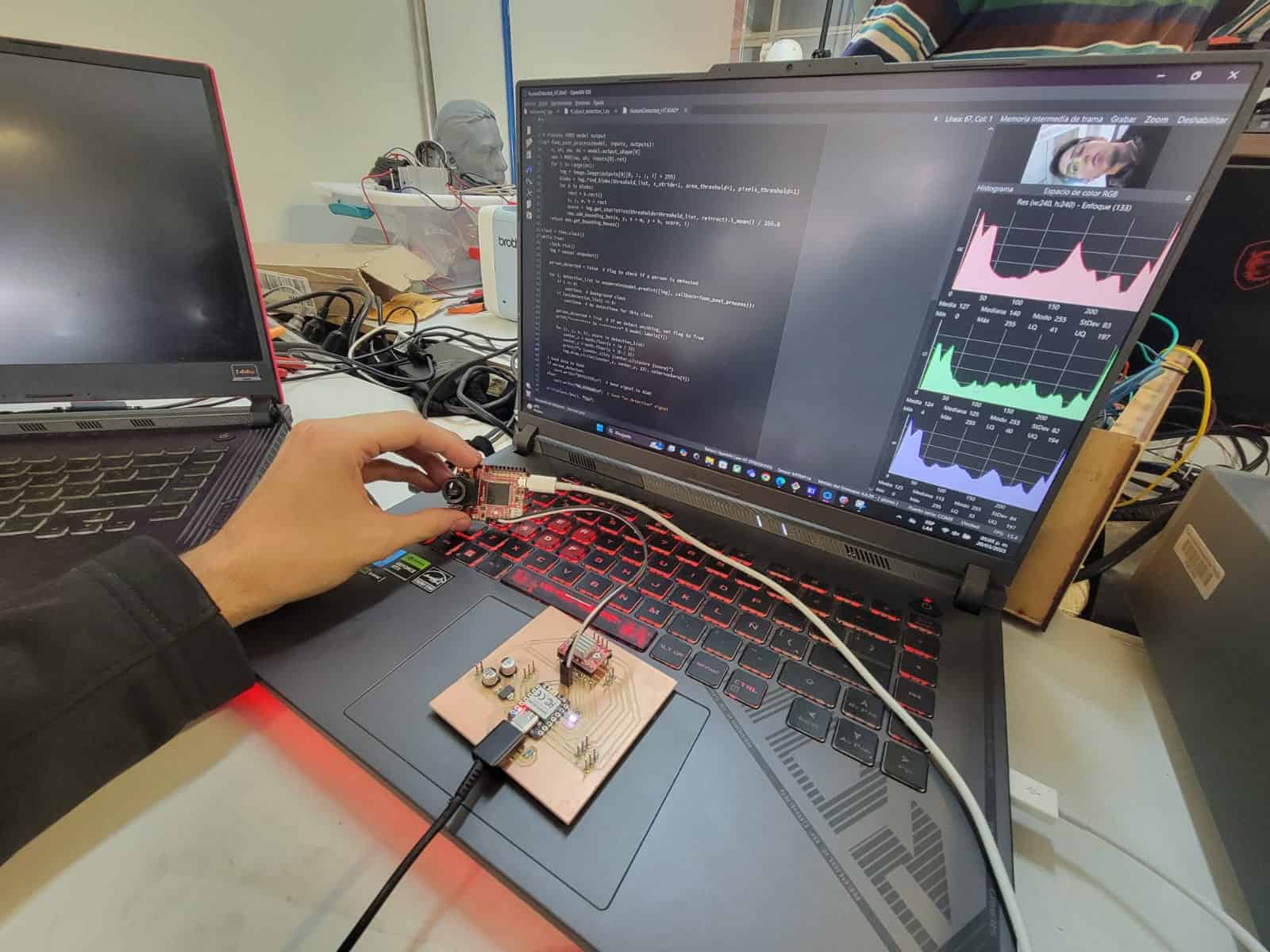
The test was succesfull, the camera was able to detect a human based on its facial features and activate the LED on the PCB, with this, I am one step closer to my final project goals.

7. Comments and Recommendations
As I mentioned earlier, when I first loaded the code into my XIAO, the H7 was connected to my computer on a different port, and I had already established the UART connection between both devices. Upon uploading the XIAO's code, my computer failed to recognize the XIAO, leading me to believe it was damaged. However, after a PC restart, everything worked fine, and the test was successful.
I have yet to identify the cause of this strange problem, but my personal belief is that the presence of both devices at the moment of upload may have triggered a serial communication conflict, causing the PC to drop the XIAO from the device list.
Another likely cause could be that the H7 may have been sending continuous UART data, causing a buffer overflow on the XIAO, leading to a lockup that prevented recognition.
The meassure that I will be taking in the future is to upload the code to the XIAO first, without connecting any other devices to my PC, this proved to be succesful in the second test.
8. Learning Outcomes
This week I built upon my previous knowledge on input devices, and worked visual inputs for the first time. Additionally, I learned about the operating principles of computer vision and developed a functional system.
A fascinating week to be sure.
