08. Electronics Production
Summary
This week I manufactured and tested a microcontroller development board of my own design, specifically, I made a modified version of my motor control PCB from week 06.
For our group assignment, we characterized the design rules for our in-house PCB production process and submitted a PCB design to a board house.
1. Electronics Production Basics
In the early days of electronics, circuits were built using point-to-point wiring, where each electrical connection was manually soldered using individual wires. This method was slow, error-prone, and difficult to scale, especially as circuits became more complex. To solve this, engineers started using perfboards and breadboards, allowing for easier prototyping, but these setups were still unreliable for long term use. Every component had to be manually connected, increasing the risk of short circuits, interference, and physical damage.
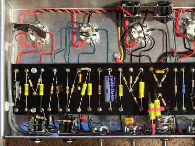
As technology advanced, a better method was developed, one that could provide compact, reliable, and scalable circuit designs. This led to the birth of the Printed Circuit Board or PCB.
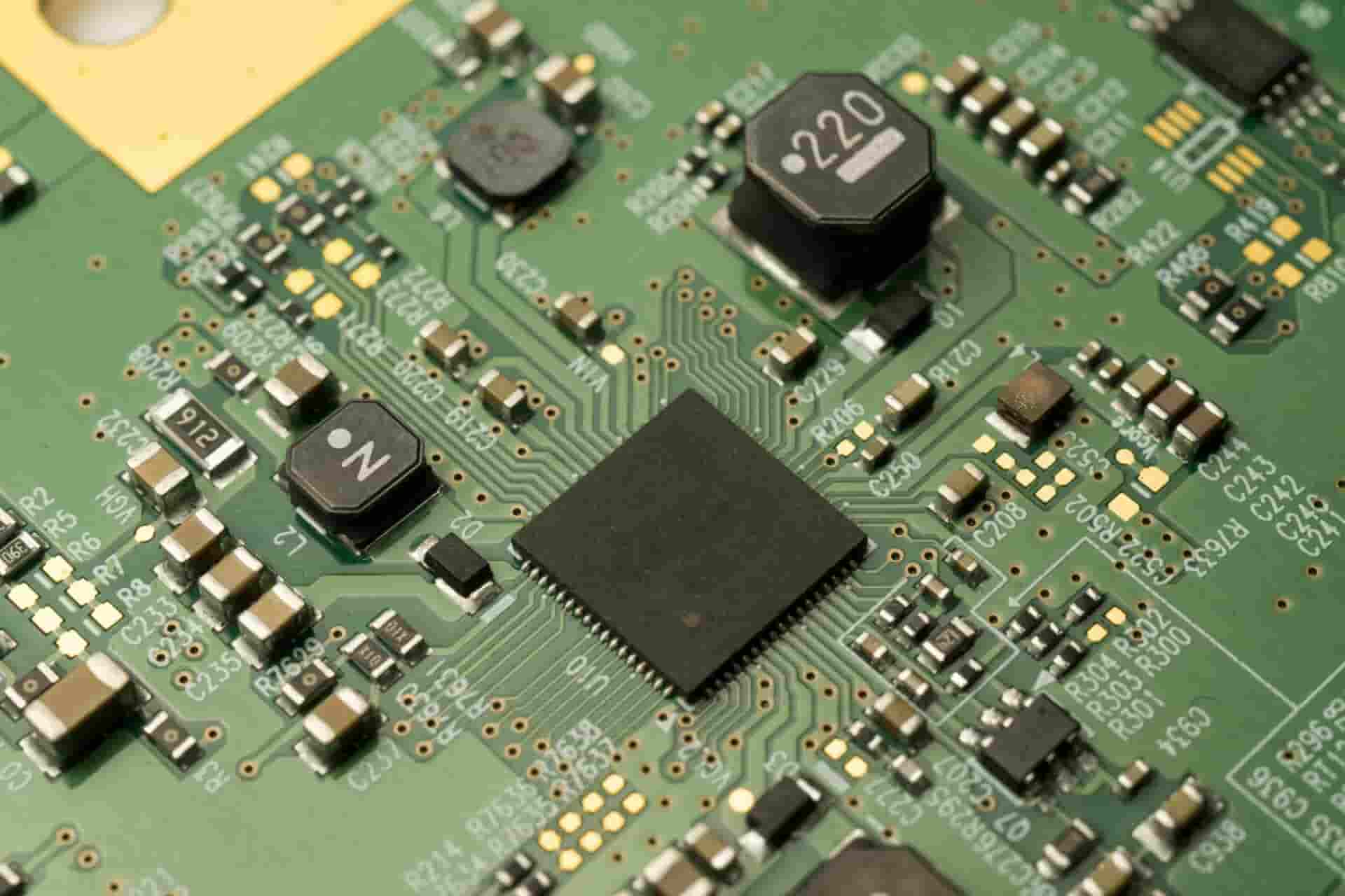
A PCB is a flat, rigid board that contains etched copper traces, replacing messy point-to-point wiring. Instead of using loose wires, electrical connections are built directly onto the board, making circuits more durable, compact, and easier to manufacture. The first PCBs were developed in the early 20th century, but their use became widespread during World War II, when miniaturization and reliability became critical for military equipment. Over time, PCB technology improved, allowing for multi-layered designs, smaller components, and automation of production.
Today, PCBs are found in everything, from computers and smartphones to spacecraft and medical devices.
At Fab Academy, we learn how to design electronic circuits and fabricate them from scratch. Instead of ordering PCBs from a factory, we learn how to mill, solder, and debug our own circuit boards using Fab Lab tools.
This approach allows us to:
- Understand the full production process from design to fabrication.
- Learn how to prototype quickly without depending on external manufacturers.
- Develop troubleshooting skills by physically building and testing circuits.
- Gain experience with CNC milling and surface-mount soldering techniques.
2. PCB Design Changes
Before beginning production, I decided to change some aspects of the PCB, let me take you through all of these changes:
2.1 Component Modification Distribution:
I rearranged my components to allow more space for wider routes and larger separations between them.
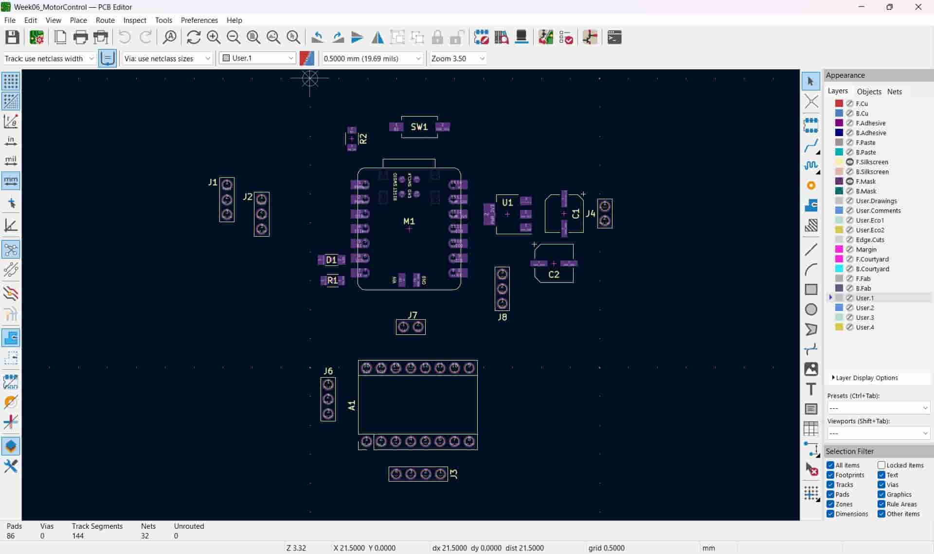
Additionally, I conducted a search in our supplies to ensure that all of the components in my design could be procured for construction. After said search, I came to the realization that we were out of 10µF, 1206 size surface mount ceramic capacitors. After consulting my local instructor he told me to replace it with an electrolitic capacitor, same to the 22µF one, with the only consideration being arranging it in the correct polarity.
Unfortunately, I made a rather silly mistake with the location of the push button, where I failed to take into account the location of the type C cable that will be connected to the XIAO. This blunder will come back to haunt me later, but we'll get there in due time.
2.2 Routing
I deleted all of the pre established routes and began from scratch. I changed the default track width to 0.8 mm to ensure more stable temperatures and signals and routed most of the components.
For the power and ground lines of the servos and stepper driver, I used 1.5 mm wide tracks, this is because these components will be working with higher currents.
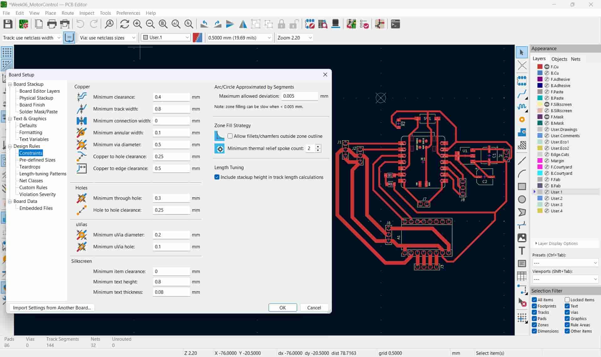
Finally, I arranged each track by hand to maximize separation, this will make soldering easier, but if you are confident in your skills I encourage you to maximize space efficiency.
2.3 Edges
I replaced the casket shape with a simpler rectangle with a width of 78 mm and a height of 75 mm, this will help simplify the milling process by a bit at the expense of space efficiency. I configured the starting points of the rectangle to be X=0 and Y=0, this way it will always be aligned with the top left corner of the page.
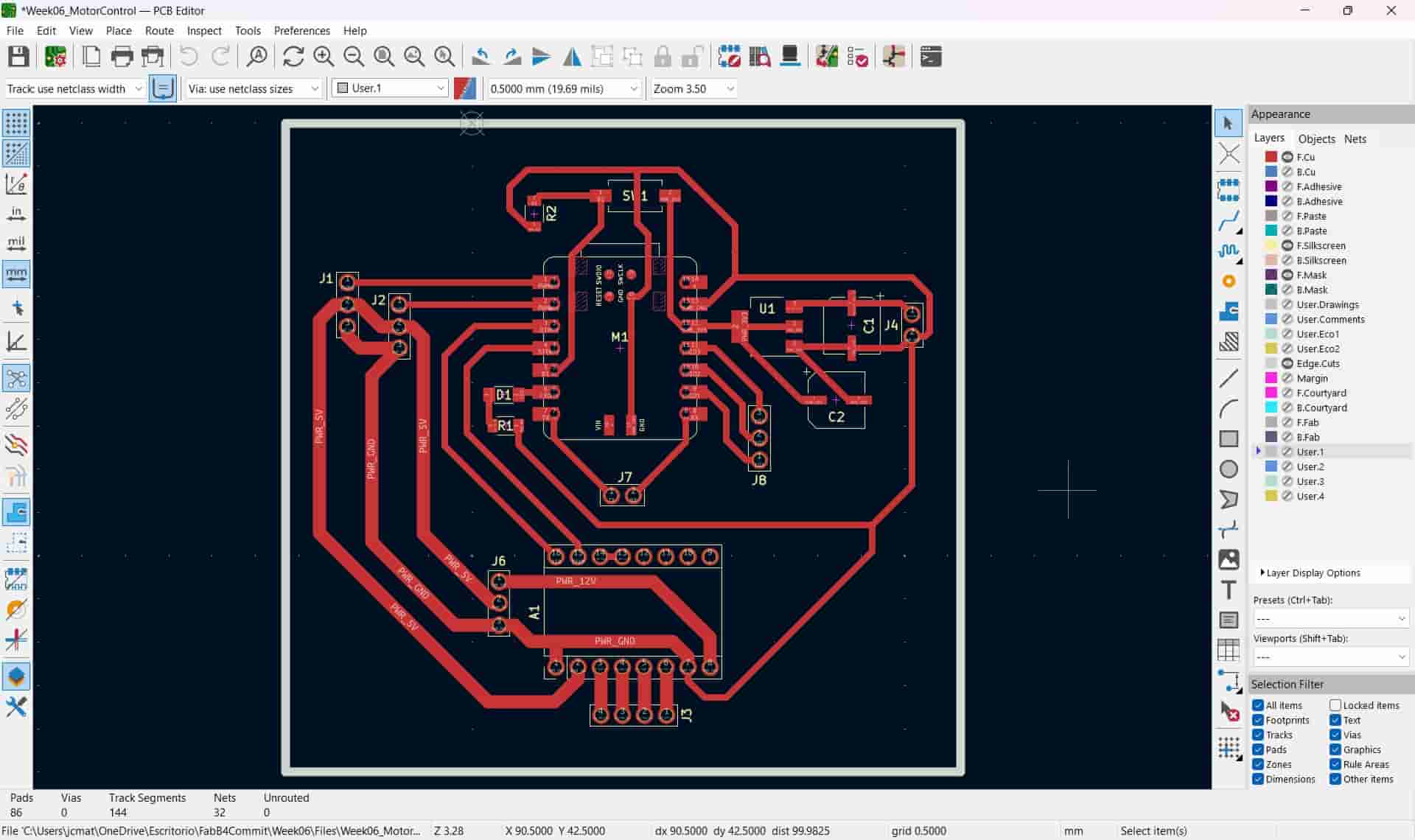
I modified the width of the line to 1 mm, this is because I thought that I would be ussing a 1 mm diameter flat endmill to carve said edges.
2.4 A4988 Driver Footprint Modification
As it was, the A4988's footprint's holes were too small, which would make inserting the component into the board and soldering it way too difficult. To circumvent this, I changed each hole to be 1.4 mm in diameter, with a pad of 2.1 mm in diameter.
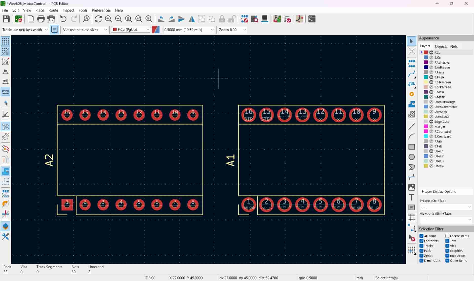
The A2 footprint is the default A4988, and the A1 is the modified A4988.
2.5 Holes
When I was informed that I could use a 0.8 mm diameter flat endmill on the PCB milling machine, I decided that I would use said endmill to drill the holes in my PCB.
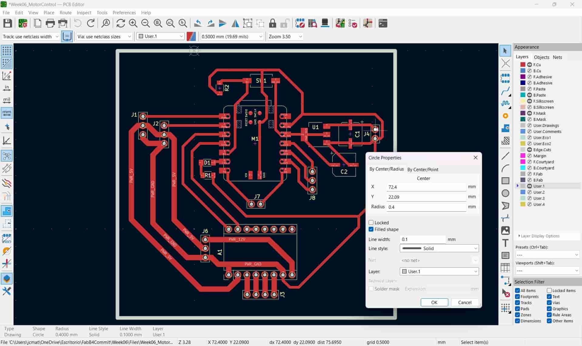
To do this, I drew a 0.9 mm hole in the footprints that required them, this was done in the User.1 layer.
2.6 Page settings
I reduce the page size to match the one of my PCB's maximum dimentions, these being the edges, with a width of 78 mm and a height of 75 mm.
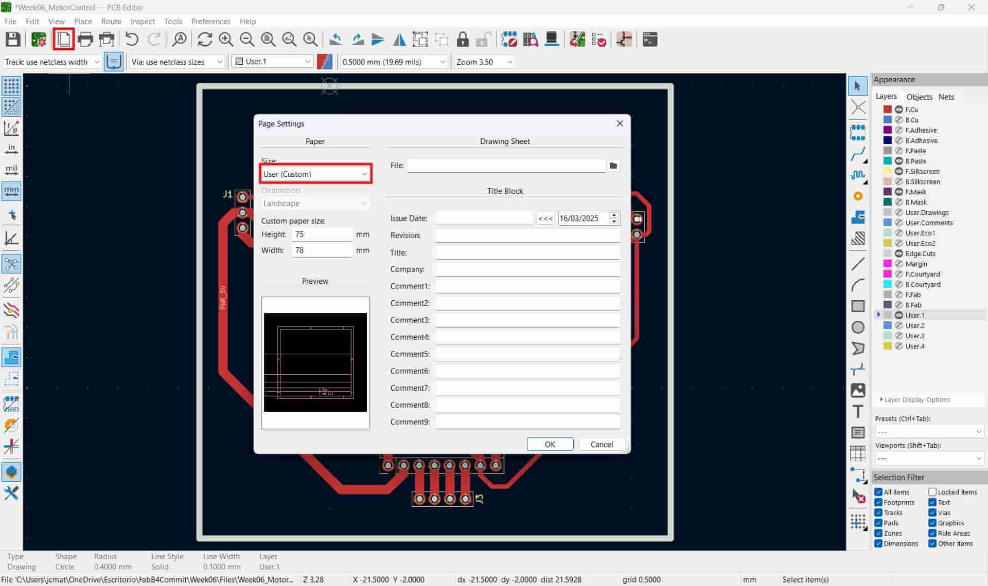
A very important consideration in your design is that no operations that will be done with a flat endmill cannot be smaller than the diameter of said endmill.
3. PDF File
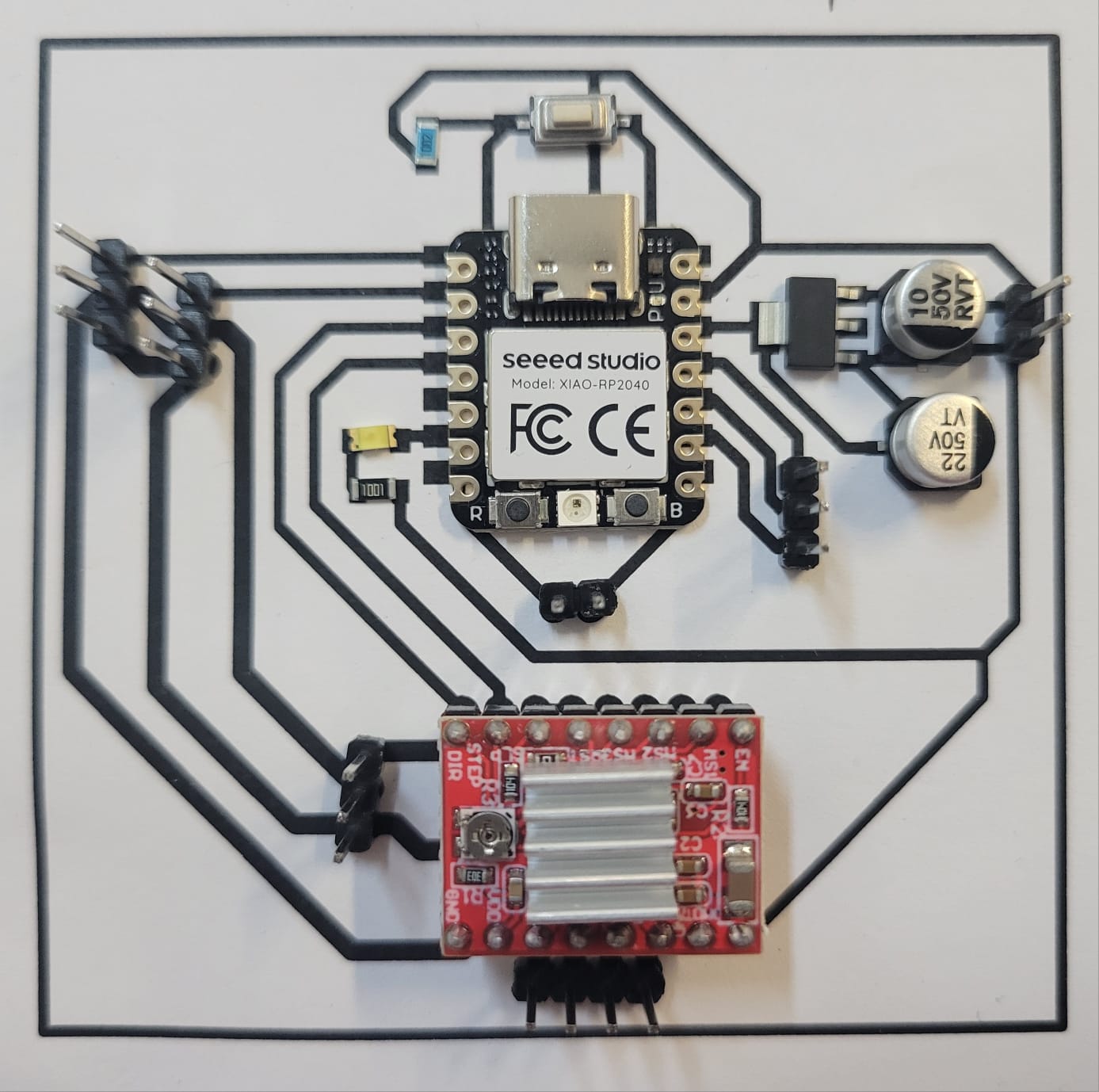
To check the placement of the components, I decided to print the design on paper on a 1:1 scale.
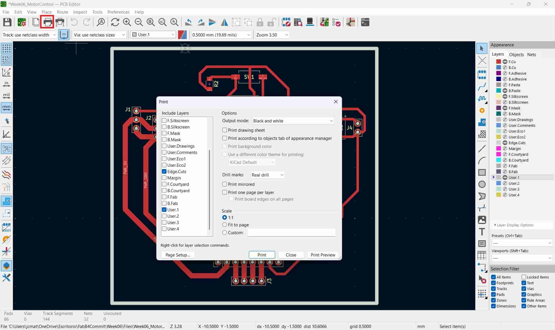
I opened the print menu, selected the F.CU, Edge.Cuts and User.1 layers and selected the print option.
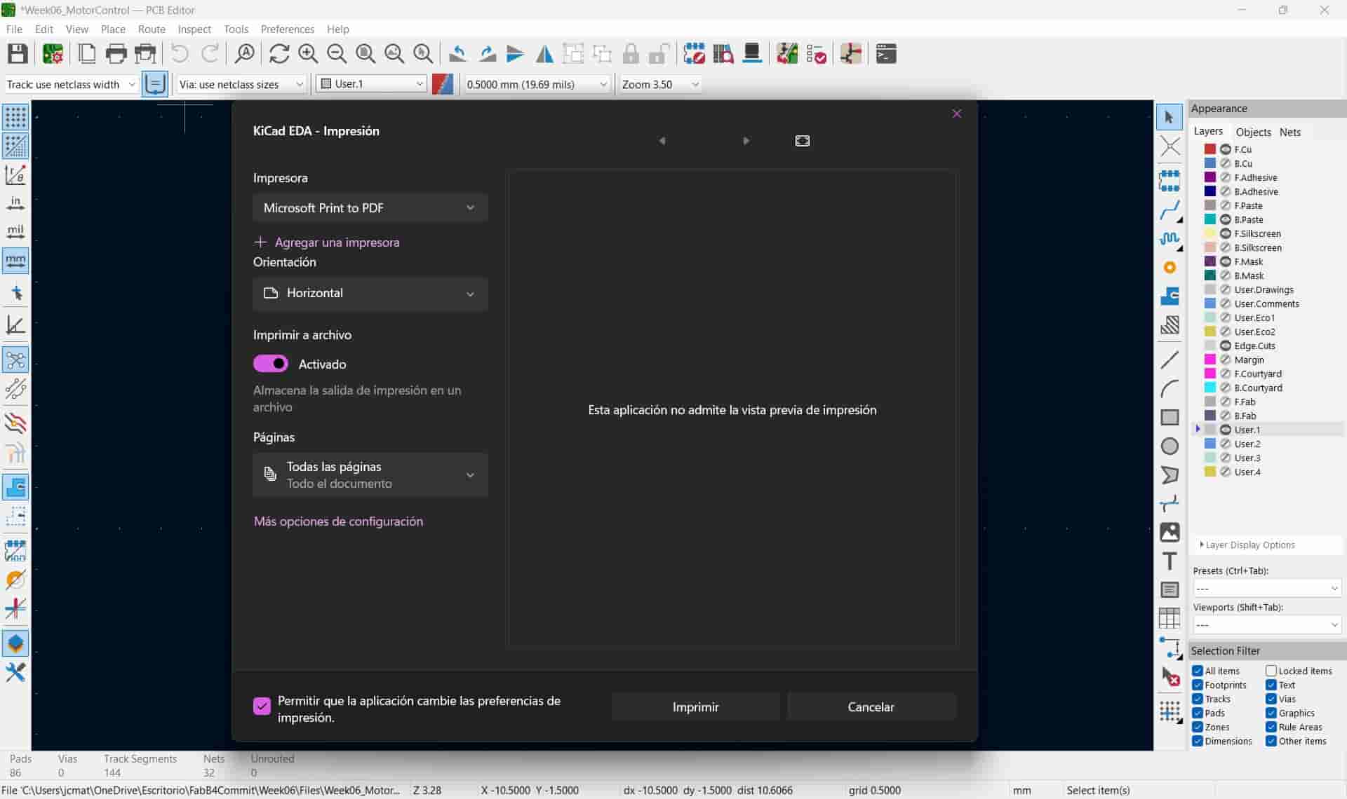
On the microsoft menu, I selected the Microsoft Print to PDF option and activaded the print to file function, after which I generated the file.
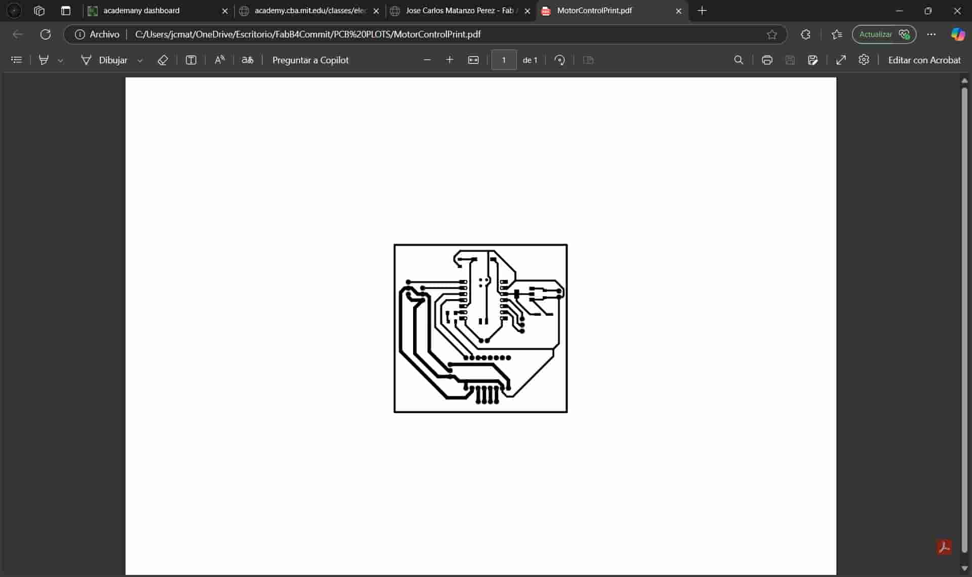
I went to the stationery shop on campus and printed my file. After returning to my lab I started to arrange my components on their respective position. Everything fit into place, but unfortunately I still failed to notice the overlapping of the button and the type-C cable, now this is just embarrassing.
4. SVG Plotting
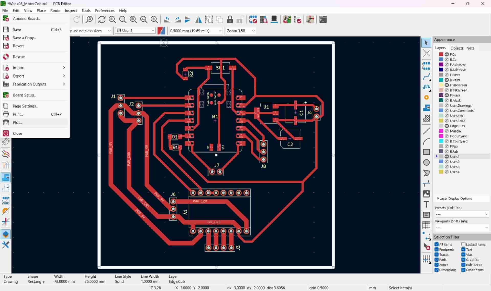
Atfer we are satisfied with the design, we have to export the sections that we want to carve into the PCB as SVG files.
I first opened the file menu and selected the plot option near the bottom. I then selected the plot format as SVG and chose the layers that I wanted to plot, which were the F.CU, Edge.Cuts and User.1 layers.
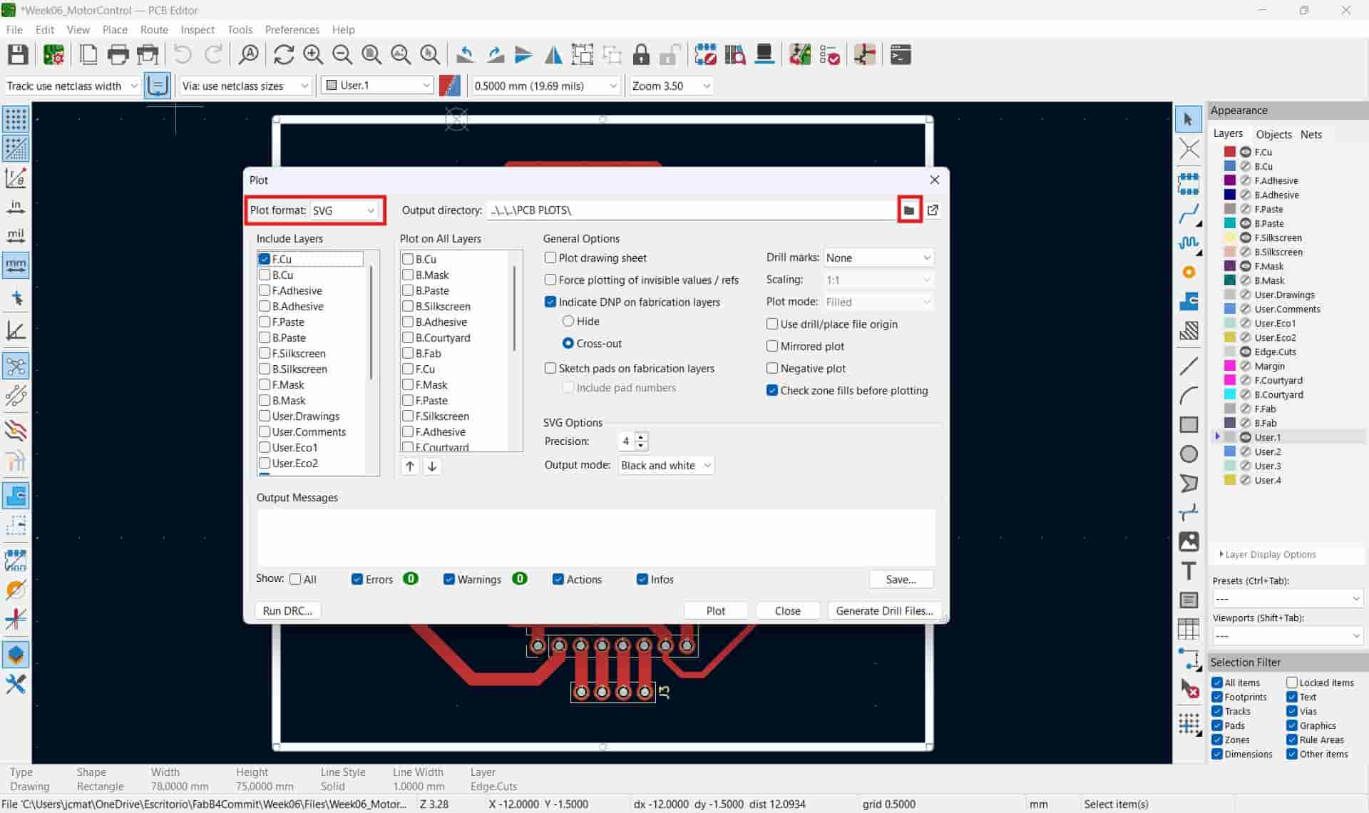
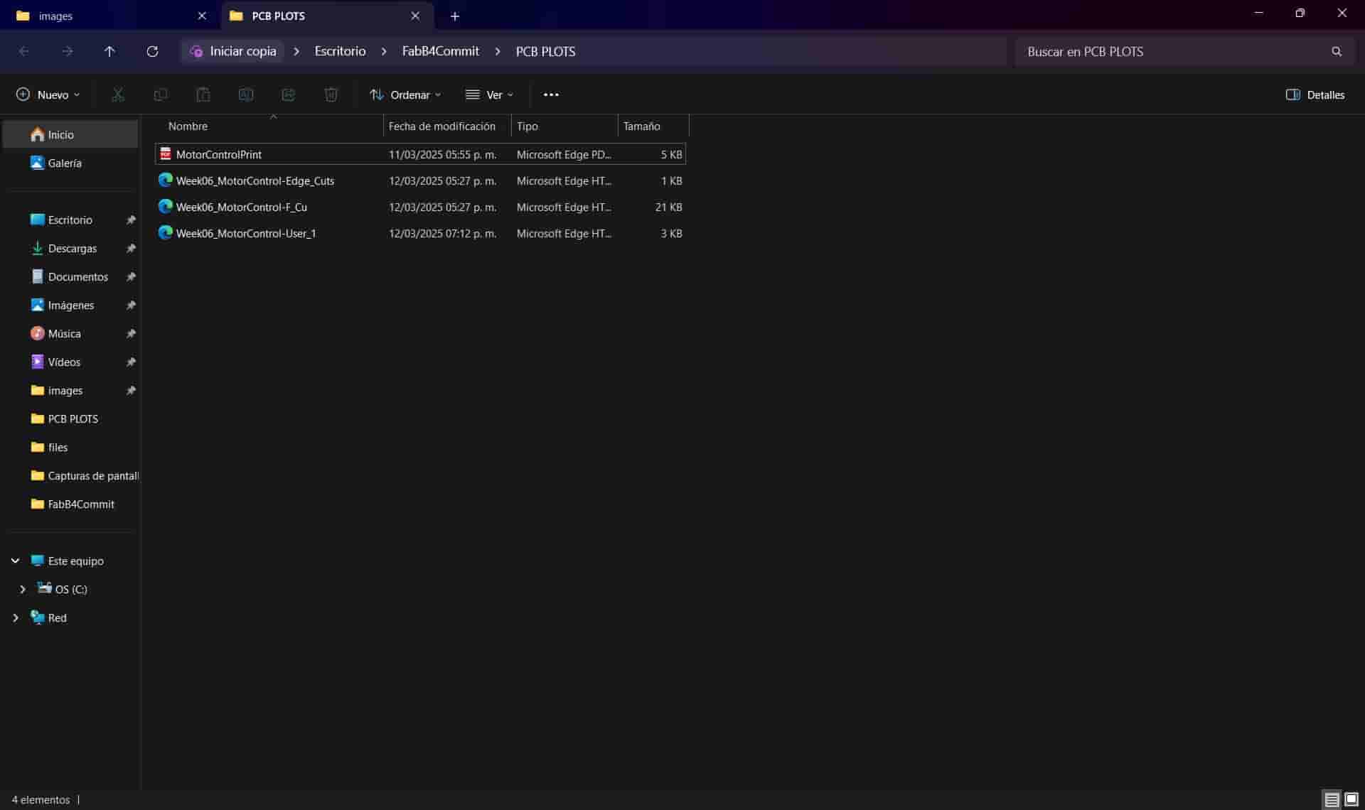
Finally, I selected the folder where I wanted the plots to be stored and selected the plot option, generating the three SVG files.
5. Toolpaths
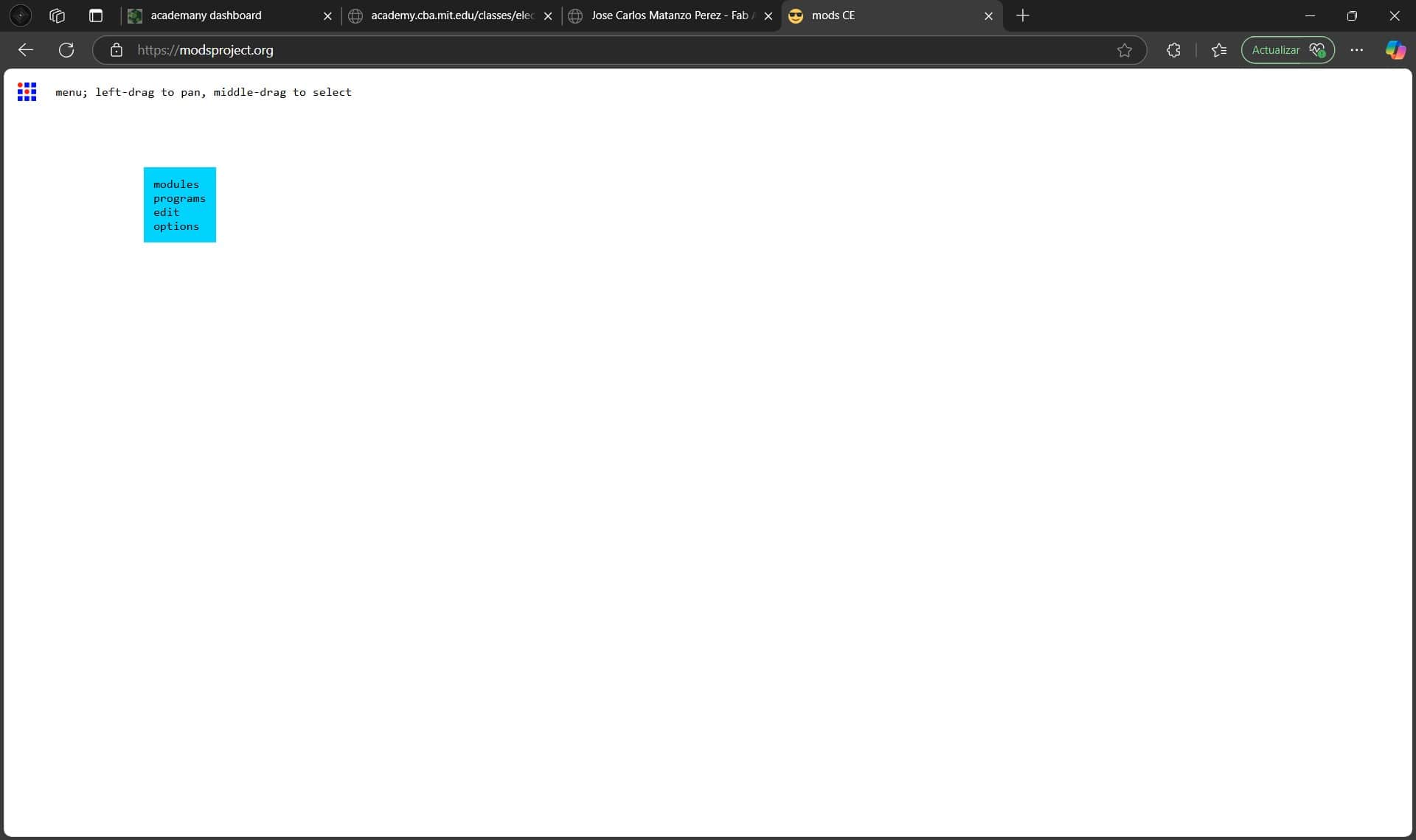
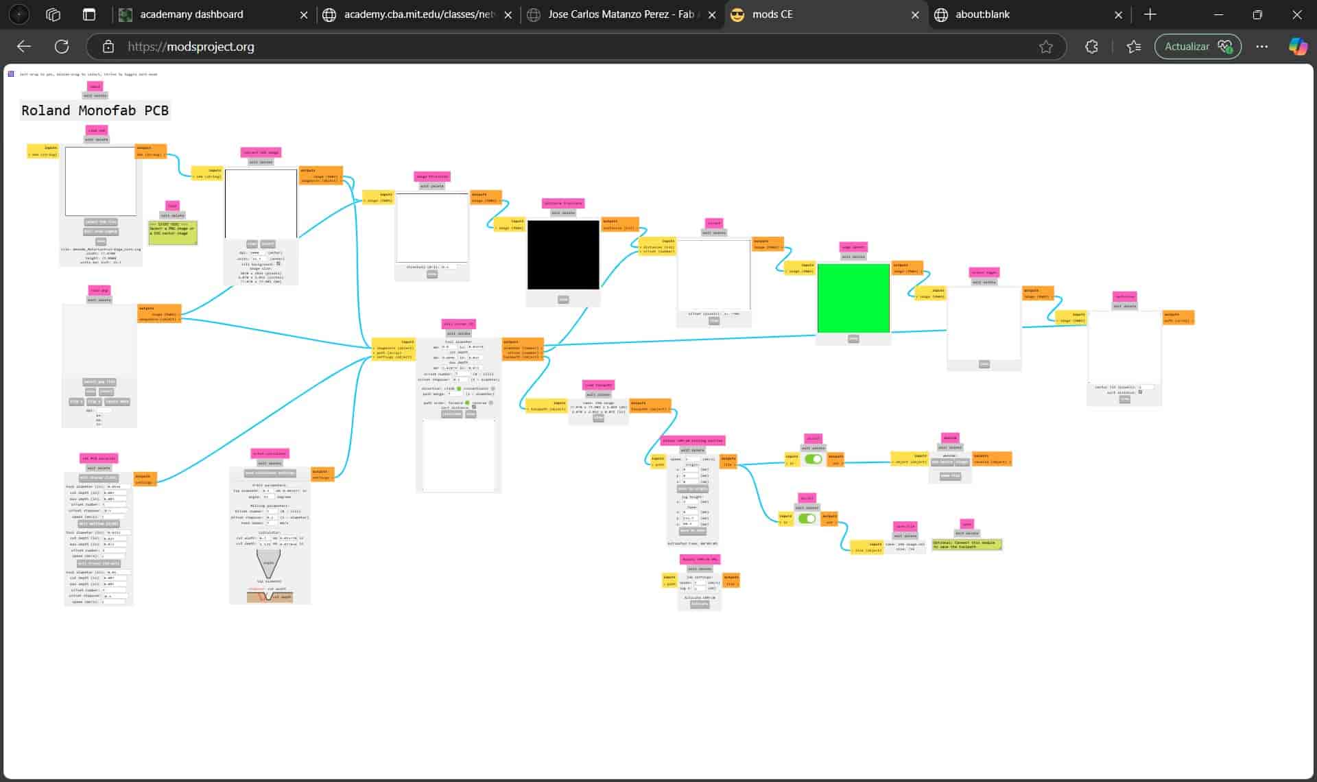
To turn our SVGs into toolpaths for the machine, we will be using the mods CE online platform.
5.1 Open Program
We open the platform on our web browser and right click on any point of the screen, which will generate a small, blue menu. We will select the program option and then the open program option.
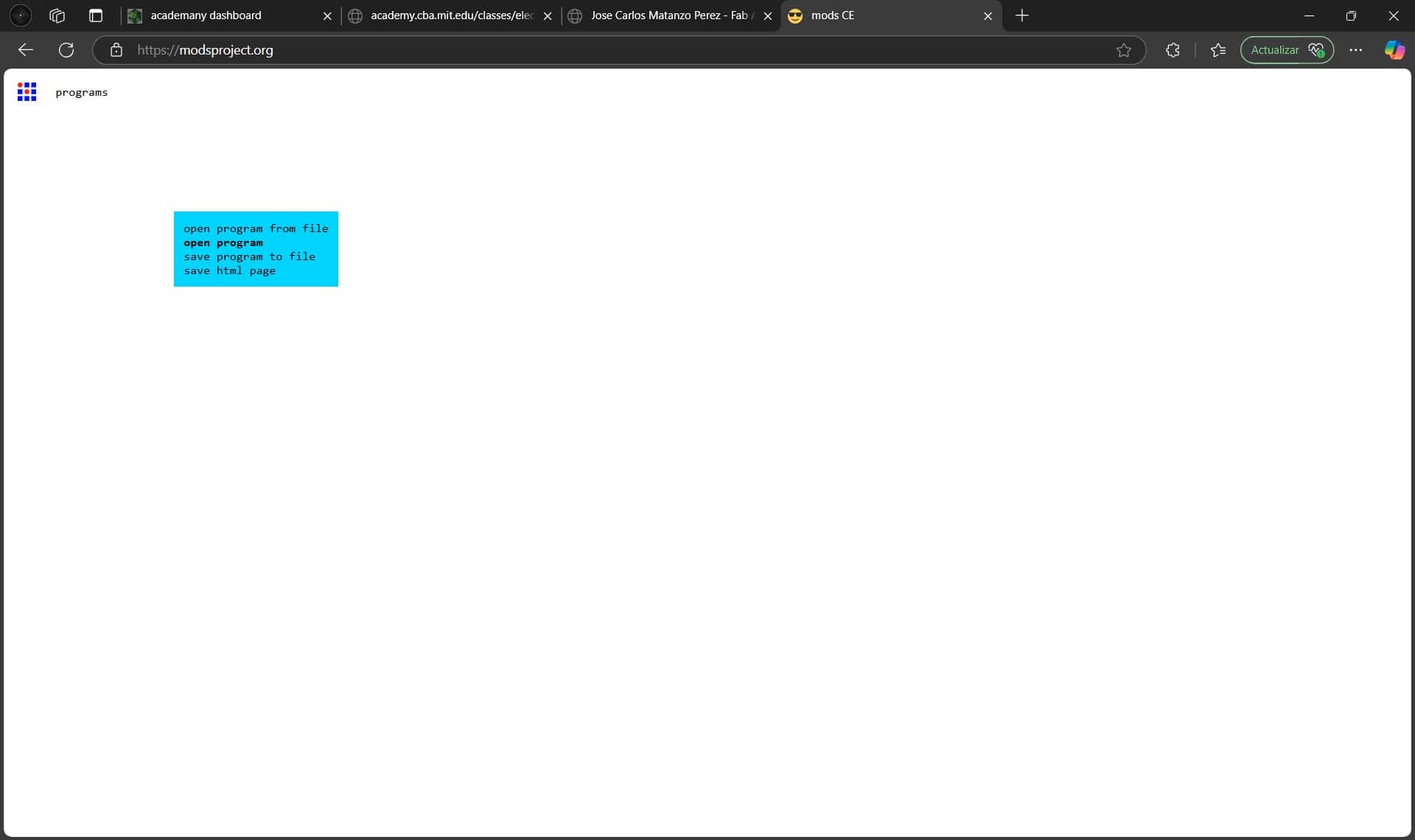
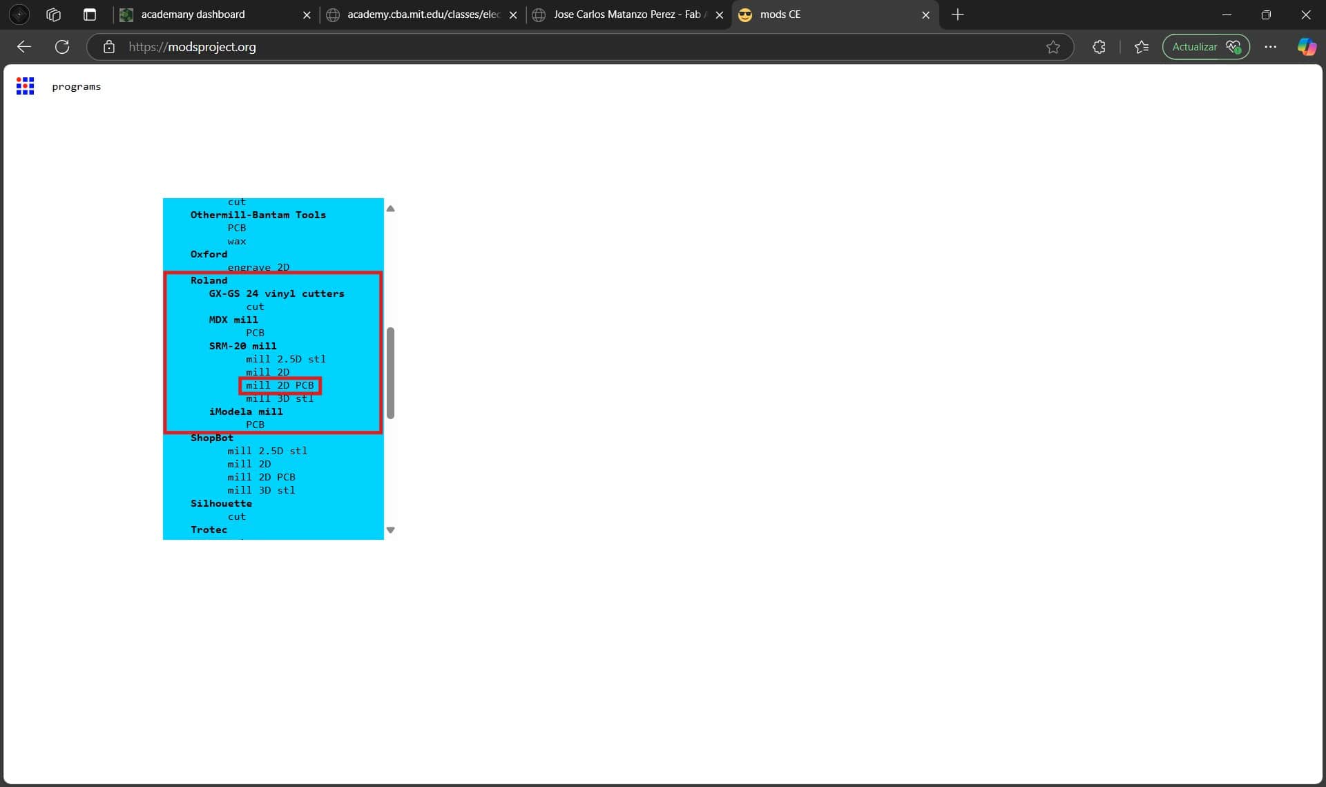
We will scroll down until we see the mill 2D PCB in the SRM-20 mill menu, this is because my lab's machine is a Roland monoFab SRM-20 desktop milling machine.
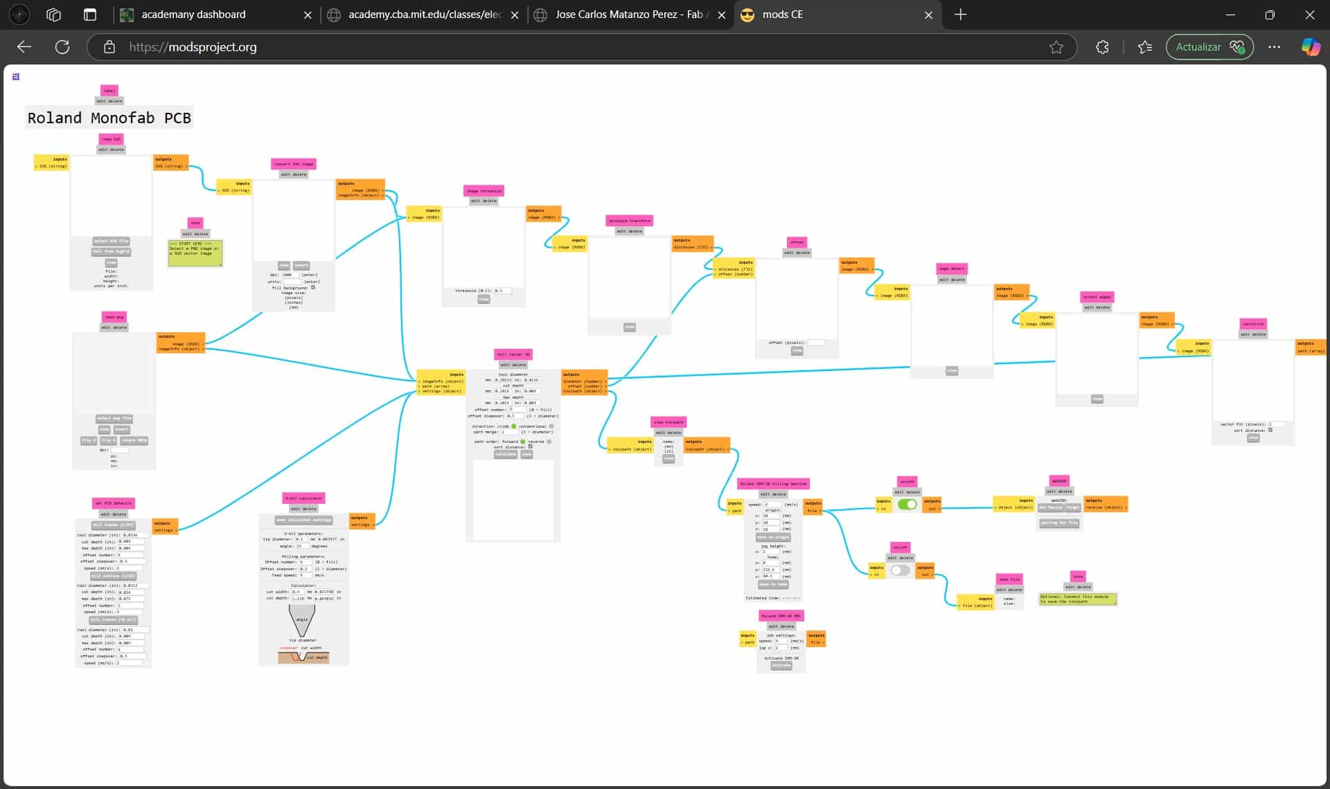
Now this may look intimidating, but using this platform is way easier than it appears.
5.2 Load SVG
The first thing we will do is load our SVG file into the machine, I recommend processing the files in the order that you will be loading them into the machine, which in my case is holes, then engraving and finally edge cuts.
We begin at the top left corner of the menu, where we will select the load SVG option and select our file. I'm starting with the holes.
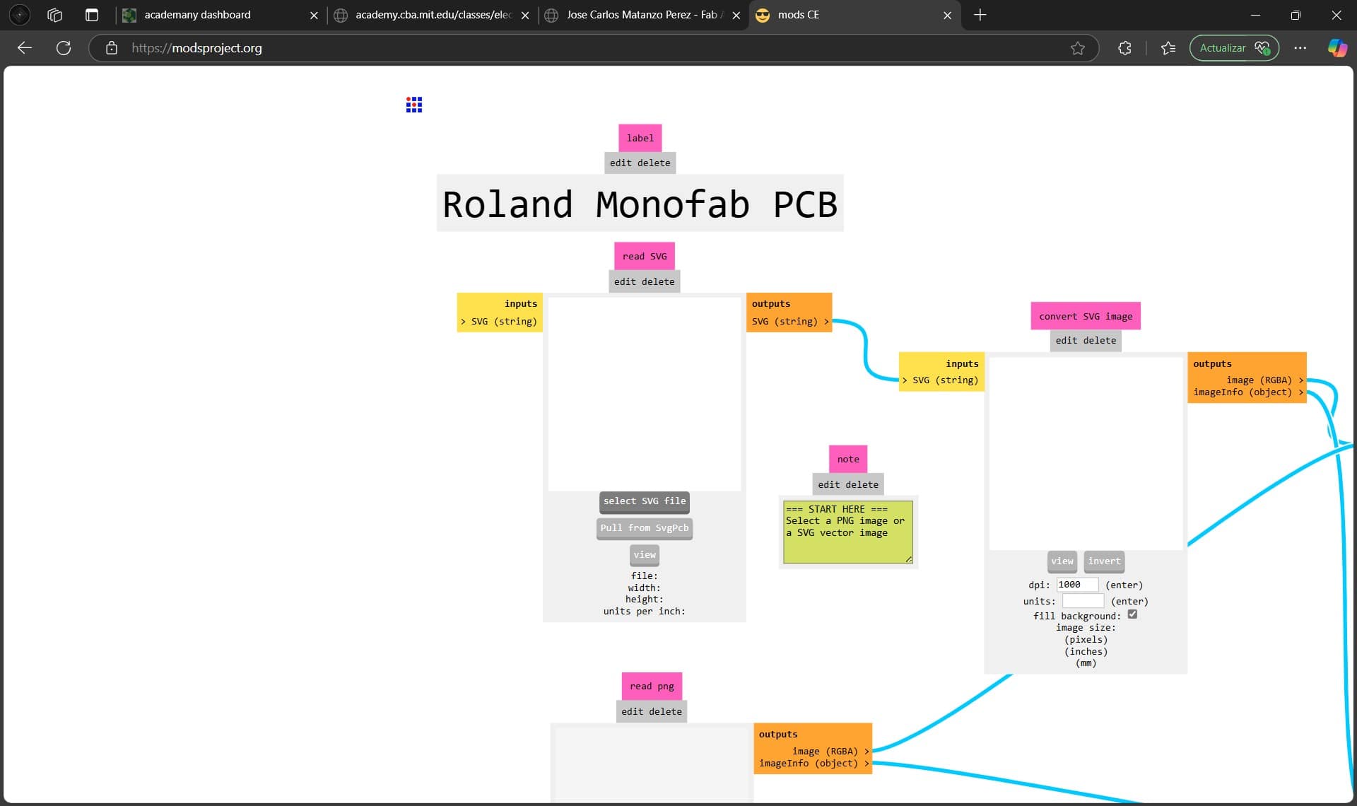
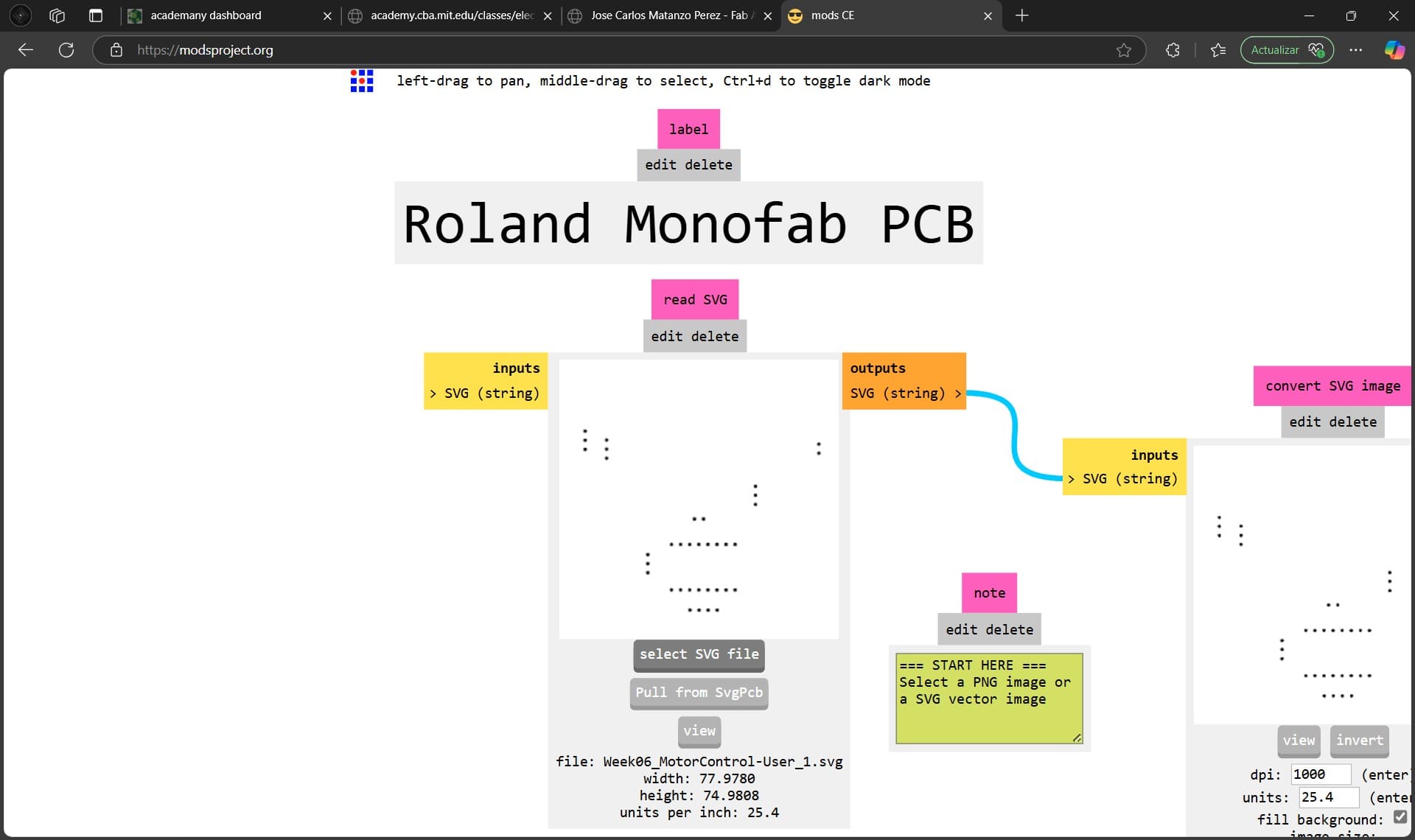
An important thing to check is that the size that appears on mods does not deviate much from the size in our design. As we can see, there is a .03 and .02 deviation, which is acceptable.
5.3 Conversion
In the menu at the right of the file menu, denoted by a magenta rectangle with the phrase "convert SVG image", we will see the same image as the one in our SVG.
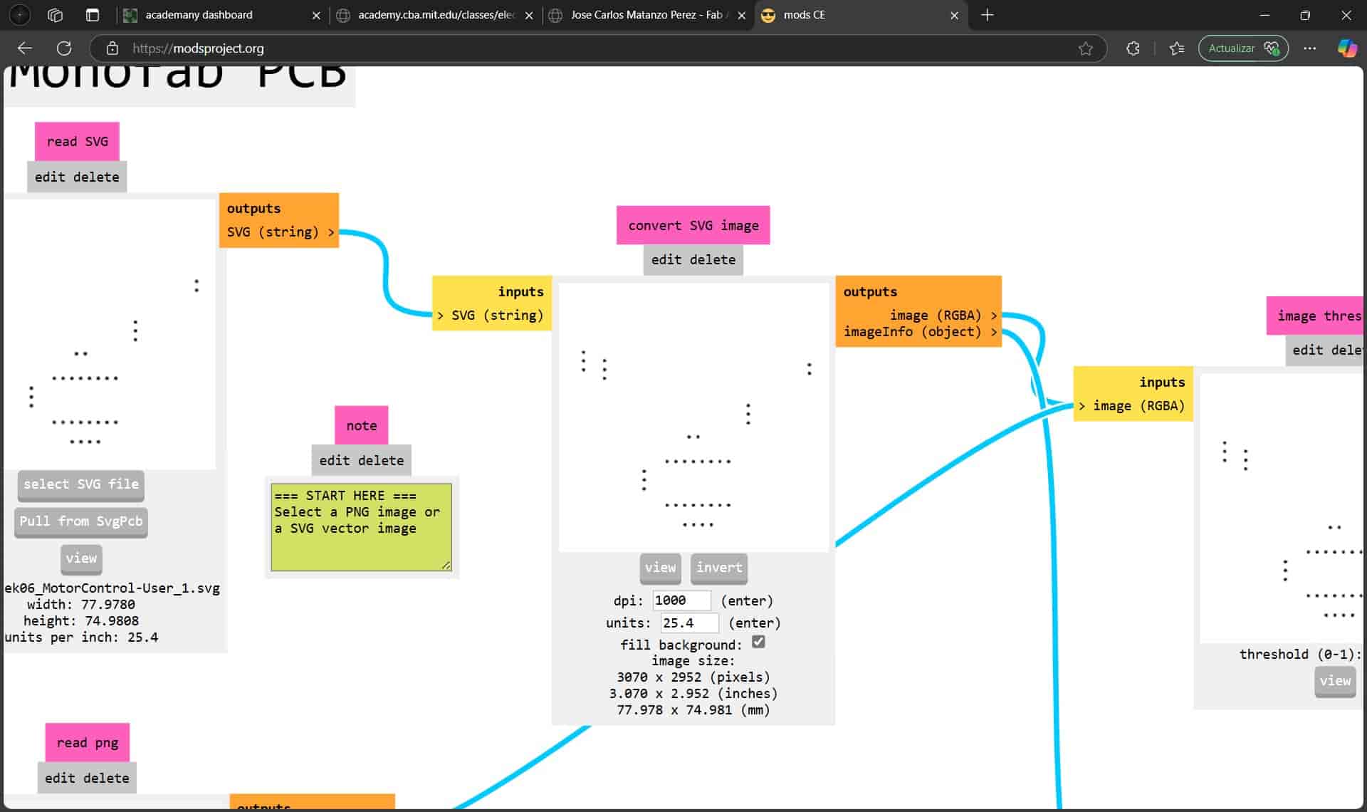
The colors in the image are extremely important, since everything in black will be carved while everything in white will be ignored. For now, we will leave it as is, since we want the holes to be carved.
5.4 Mill Outline - Holes
Since the holes need to go through the entire PCB, we will select the mill outline (1/32) option in the set PCB defaults menu, located at the bottom left corner of the screen. This will generate default parameters for the operation.
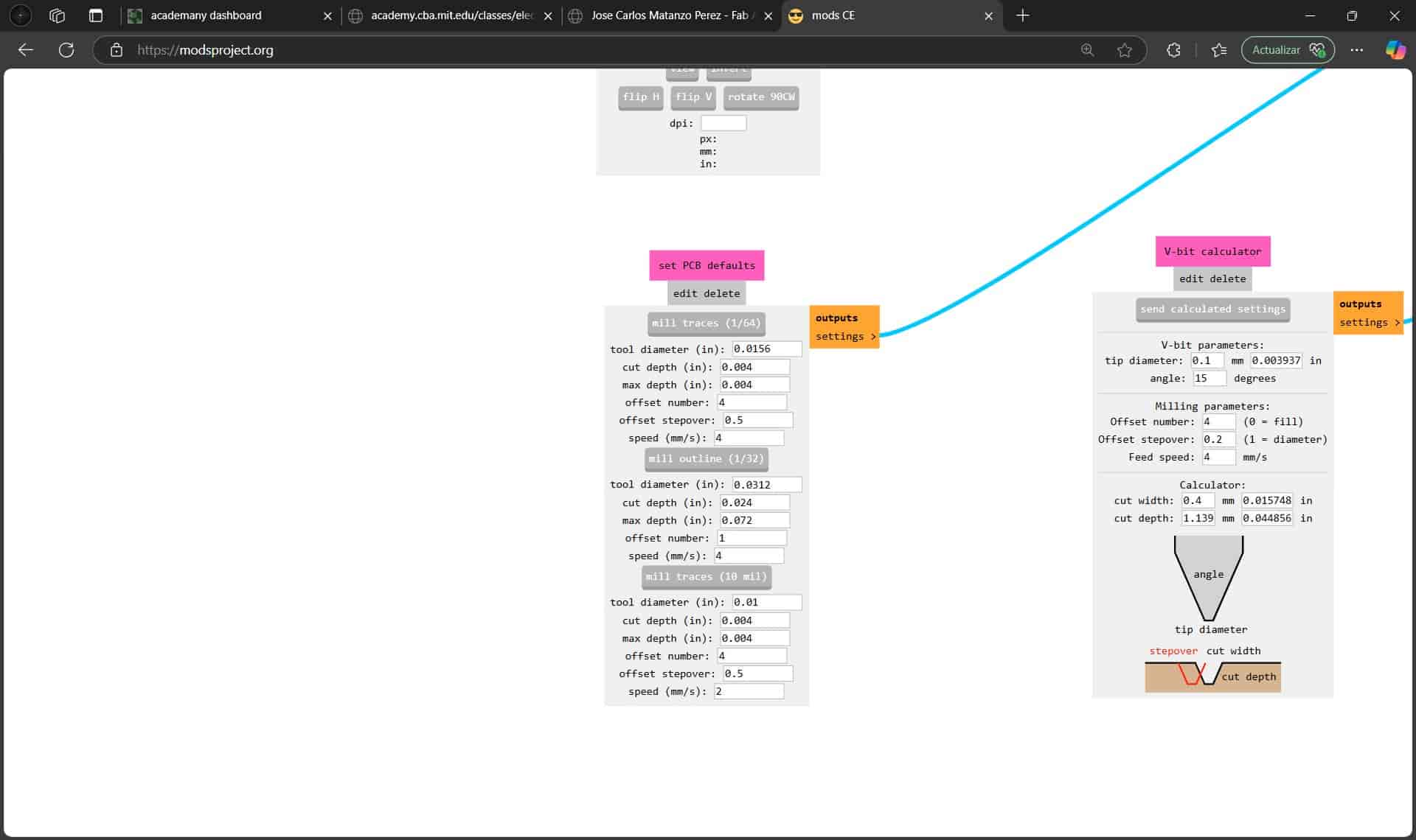
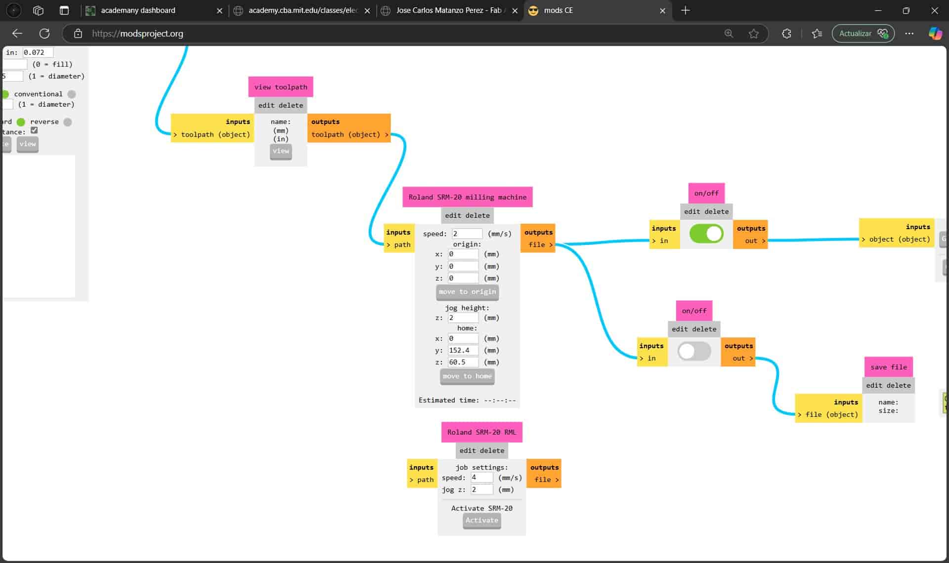
By following the blue line, we can find the mill raster 2D menu, where we can change some of the parameters of the operation, the parameter that I changed was setting the tool diameter to 0.8 mm.
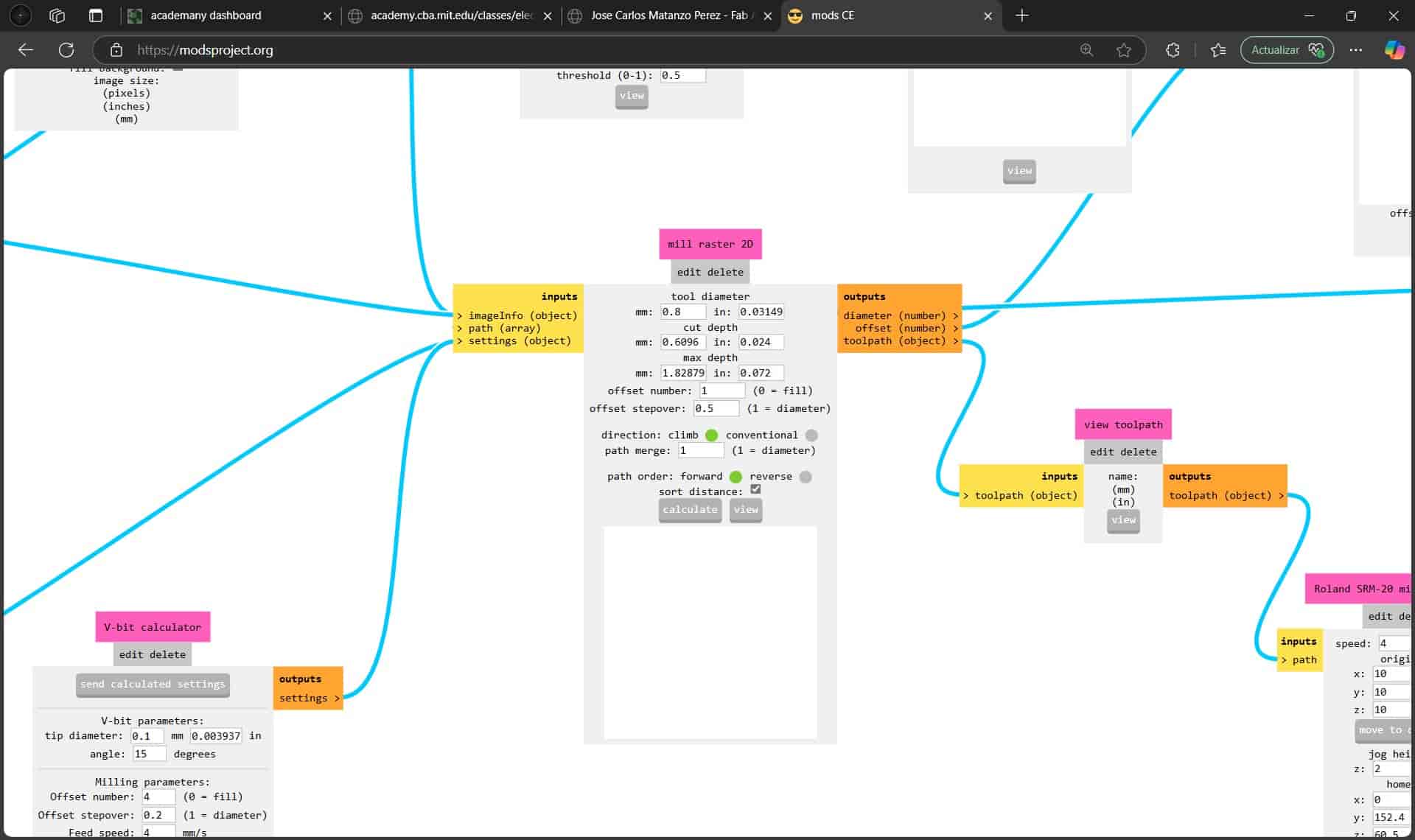
We follow the blue line again to the Roland SRM-20 milling machine menu, here we will change the x, y and z origins to 0, and set the speed. In my case I set the speed to 2 mm/s, since I'm using a smaller tool that can break easily at higher speeds.
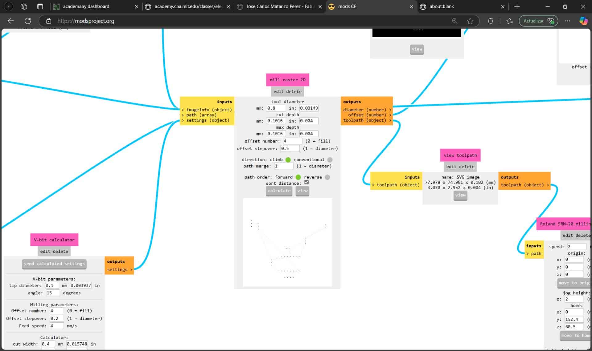
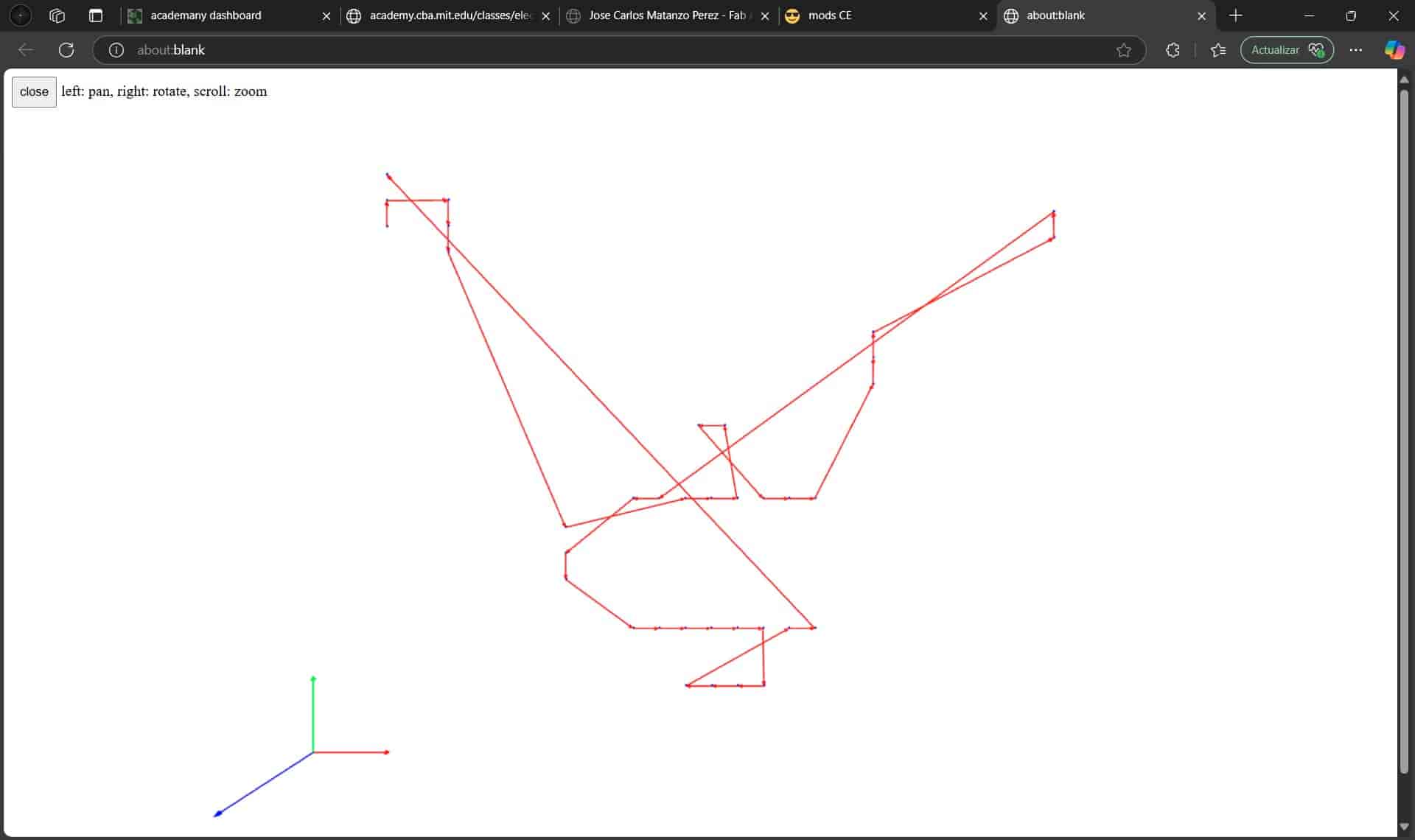
Once we are ready, we go back to the mill raster 2D menu and select calculate, generating our toolpath. By pressing view we will open a tab where we can get a more detailed view.
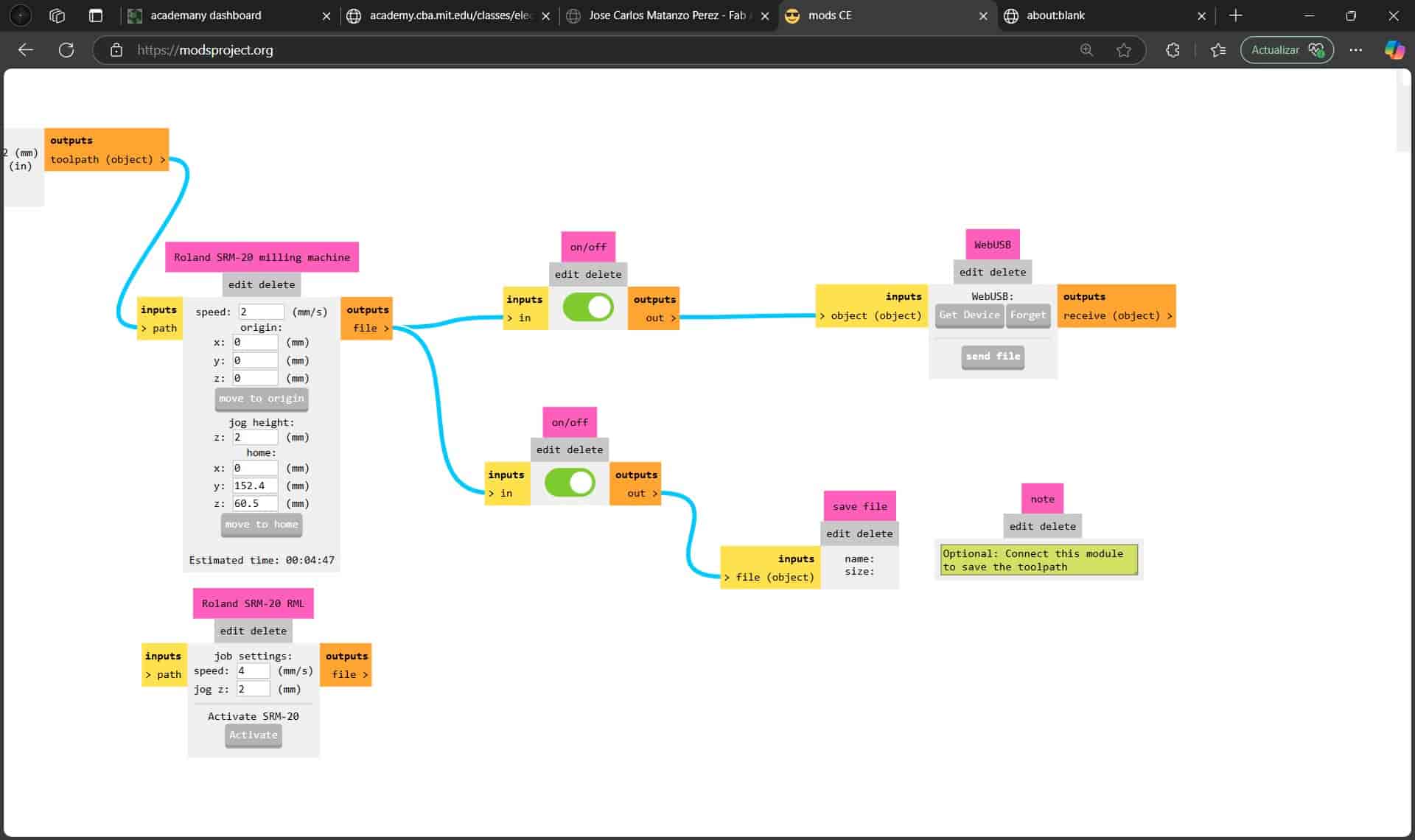
If we are satisfied with the results, we will activate the save file option at the right of the Roland SRM-20 milling machine menu, we calculate again, and our .rml file will be downloaded, this is the file that we will be using in the machine.
5.5 Mill Traces - Tracks
The mill traces follow a similar procedure, beginning with the selection of the correct SVG file, in my case it's the F.Cu layer.
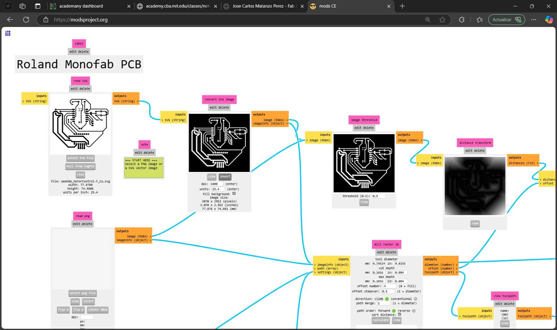
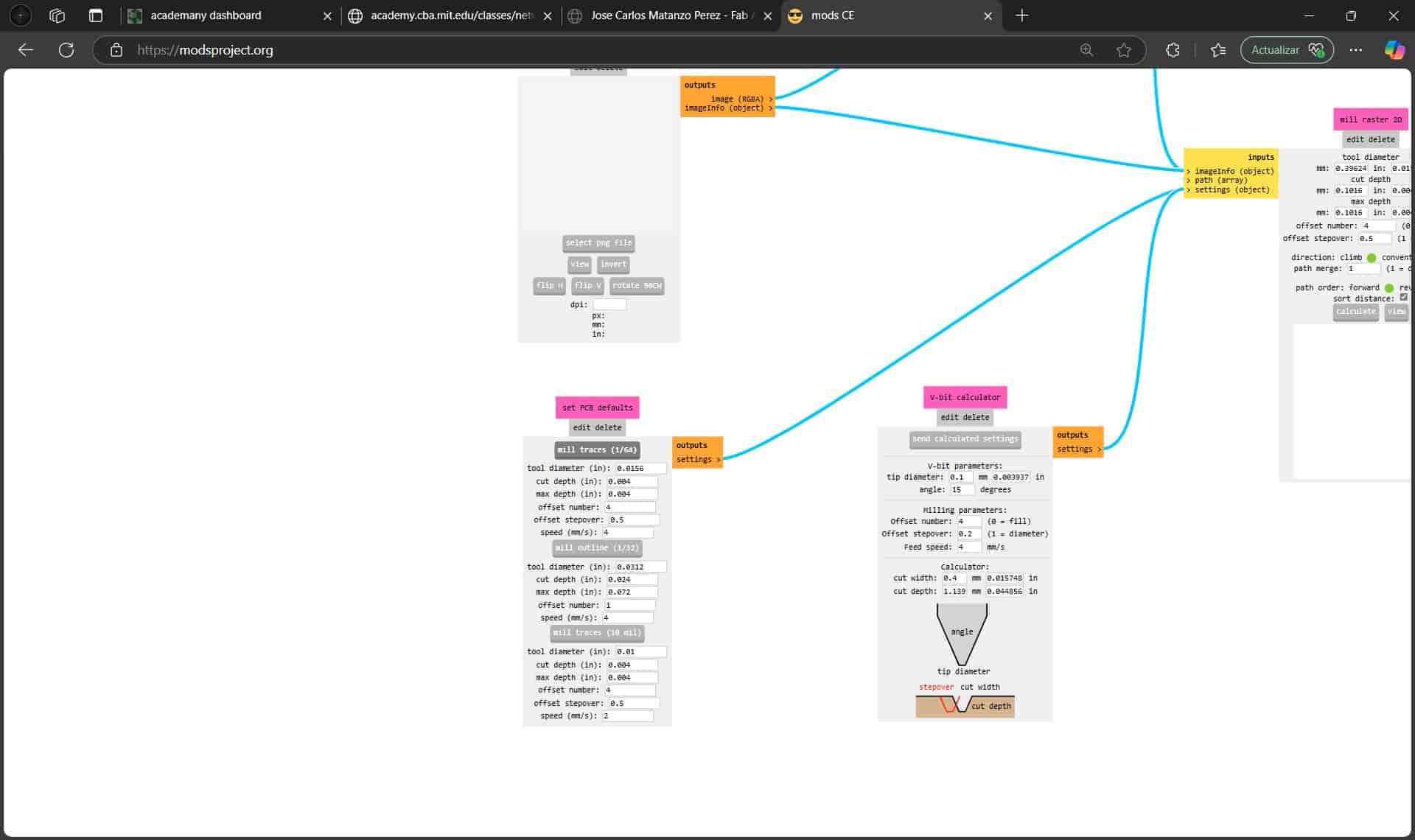
After selecting the file and checking the dimensions are the same as the previous file, we proceed to invert the colors in the image, which will leave our paths unchanged but will tell the machine to remove the material surrounding them.
This time I won't be changing any of the parameters except for setting the x, y and z origin as 0, which is required in all of the toolpaths. One parameter worth noting is the offset amount, which will determine how many times the cutter will go around the tracks, more offset means cleaner tracks to the expense of a longer process.
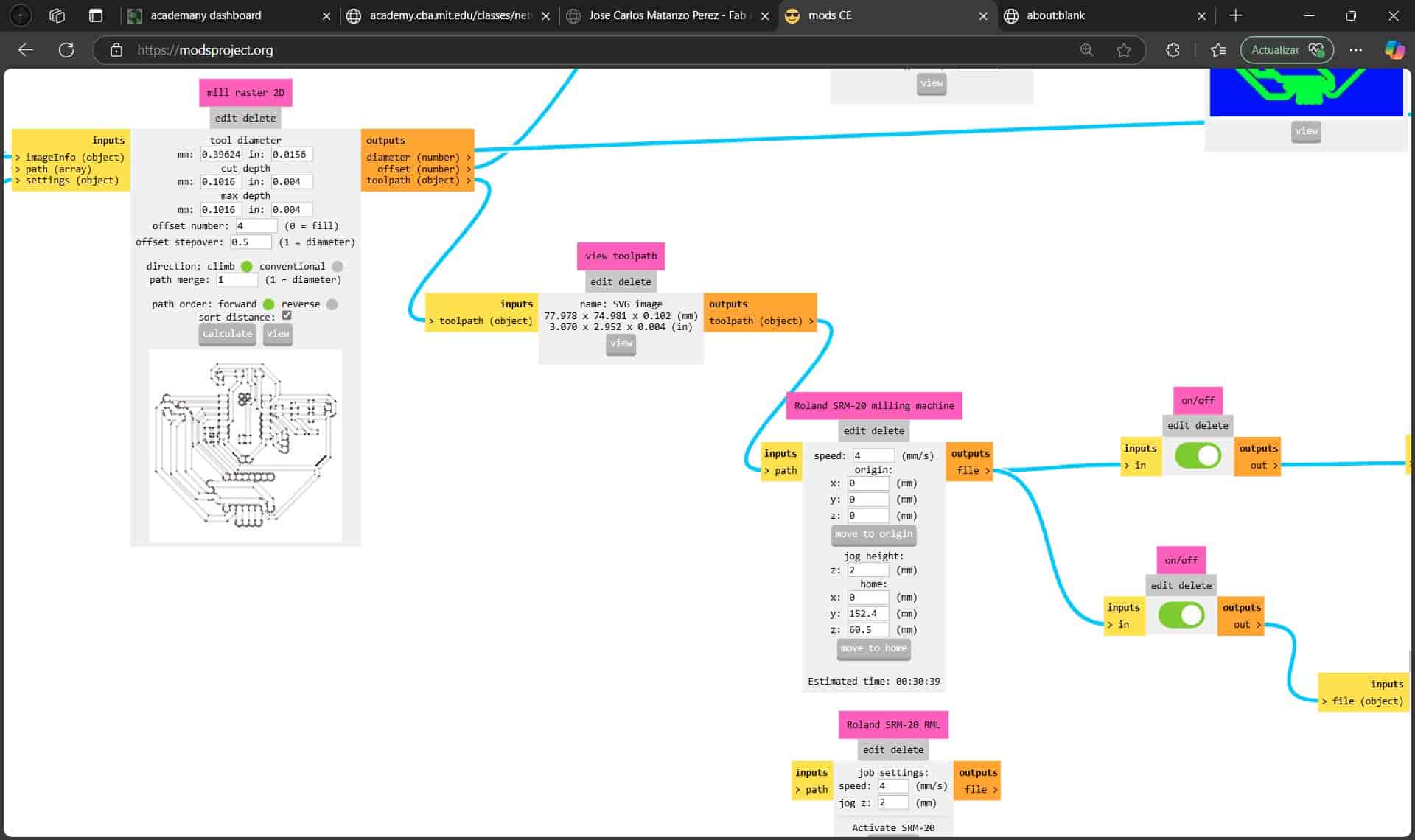
We then calculate and save our file. I recommend enumerating the files in the order that you will input them into the machine to avoid confusion.
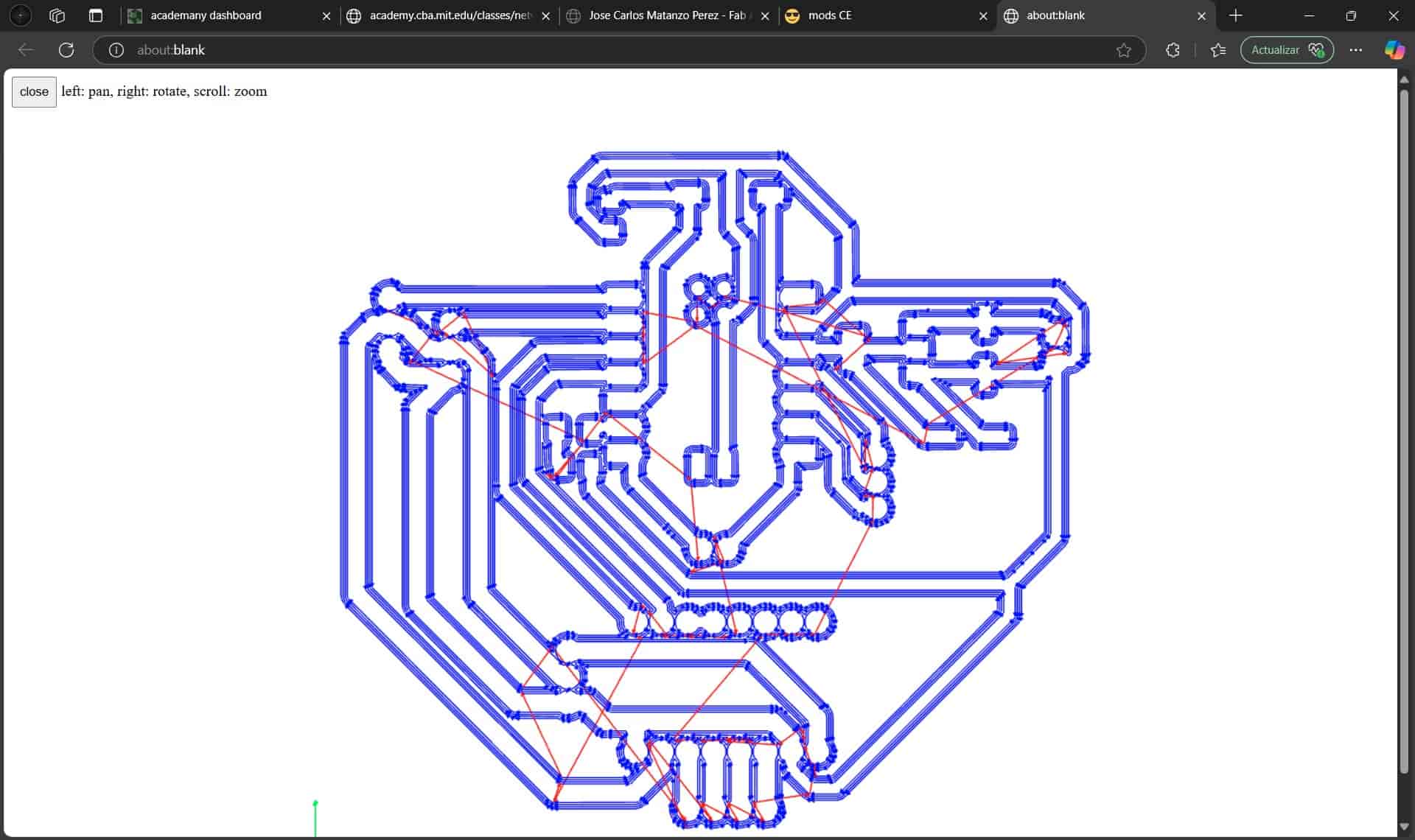
5.6 Mill Outline - Edges
Finally, we will configure the toolpath for our outer edges.
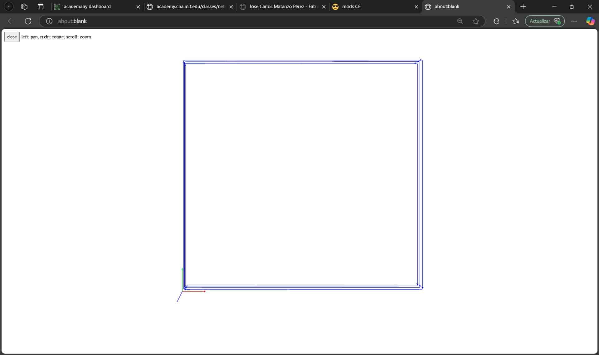
This follows the exact same process as the toolpath of the holes, with the exact same parameters.
Once we have completed all toolpaths, we are ready to begin production.
6. Roland monoFab SRM-20
As mentioned before, the machine that we will be operating is a Roland monoFab SRM-20 desktop milling machine, the material that we will be making our PCB out of is an FR-4, fiberglass-reinforced epoxy laminate plate, given to us by our local instructor.
This machine is very safe, with the greatest possible dangers to us being the rupturing and projection of the tool or the inhalation of the fiberglass and epoxy dust, which is why the machine is covered by an enclosure.
6.1 Download Software
To operate the machine, we install the necessary program and driver for the monoFab, which were provided to us by the local instructor. This software won't start unless the computer is connected to the machine.
6.2 Machine Activation
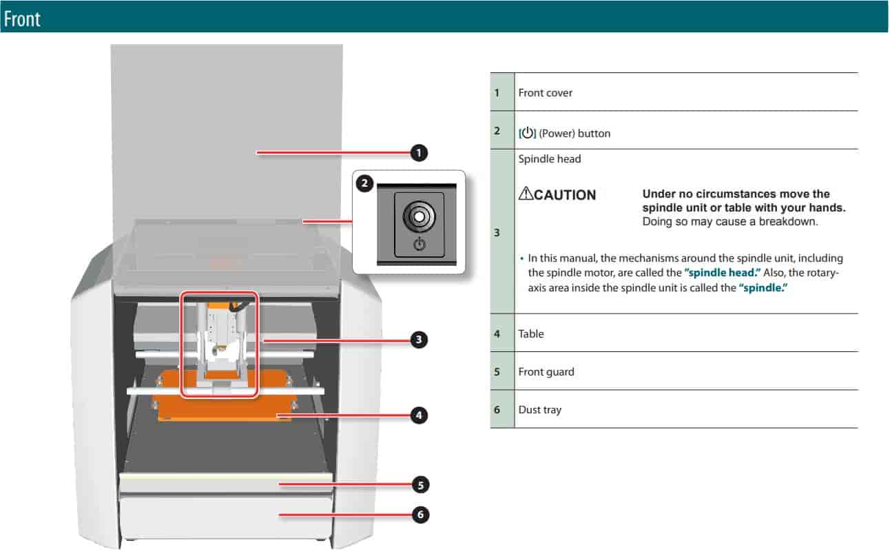
We plug the machine into an outlet, press the power button on the top, this will activate the machine, at which point the toolhead will begin moving to perform a self calibration. After it ceases movement, we connect the USB cable to our computer.
At this point, we can open the program.
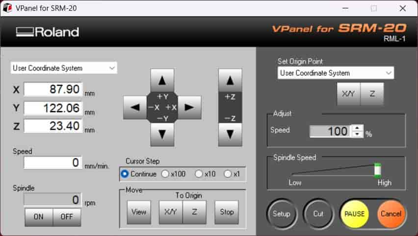
The control panel is quite simple and intuitive. It includes buttons to move the toolhead along the X and Z axes, while the machine bed moves along the Y axis. The movement speed can be adjusted between free movement, 1 mm, 0.1 mm, and 0.01 mm precision steps. We can set the zero coordinates (0,0,0) for all three axes, and by using the "To Origin" buttons, we can align the toolhead with these coordinates.
For the spindle, we can activate it and control its speed as needed. During the milling process, we can load and start a file using the "Cut" button, while the "Pause" and "Cancel" buttons allow us to stop or interrupt the process if necessary.
6.3 Secure Material
To process our material, we have to adhere it to a sacrificial MDF board that will be screwed on top of the machine bed. As it turns out, we were all out of sacrificial boards, so I had a quick callback to Week 3 and cut out a substantial amount of them using the laser cutter.
Once we have our sacrificial board, we will cover the fiberblass side (the side without any copper) of the FR-4 plate with double-sided adhesive tape and stick it firmly onto the sacrificial board, while trying to keep it parallel and without touching the copper with our fingers, since this accelerates oxidation.
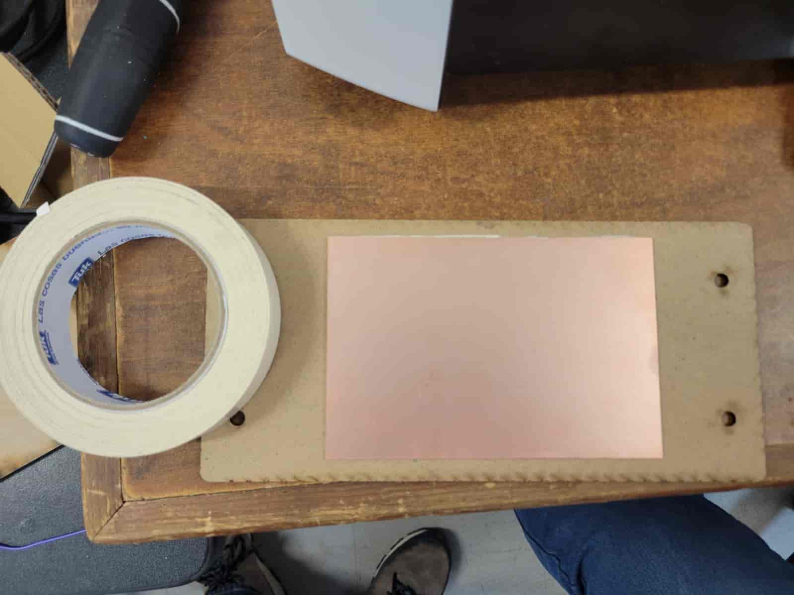
Once ready, we will move the machine bed towards us to get better access to it, after which we will screw the board with our plate on it.
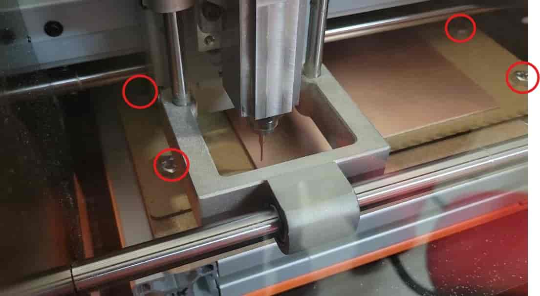
6.4 Install Tool - Flat Endmill
Since we will be starting with the holes, we will be using the 0.8 mm flat endmill. To install it we must lossen the black screw near the bottom of the spindle using the correct allen key, after which we will insert the tool and tighten it. It's extremely important to secure the tool very tightly, since a loose tool will create tons of trouble, as I unfortunately found out.
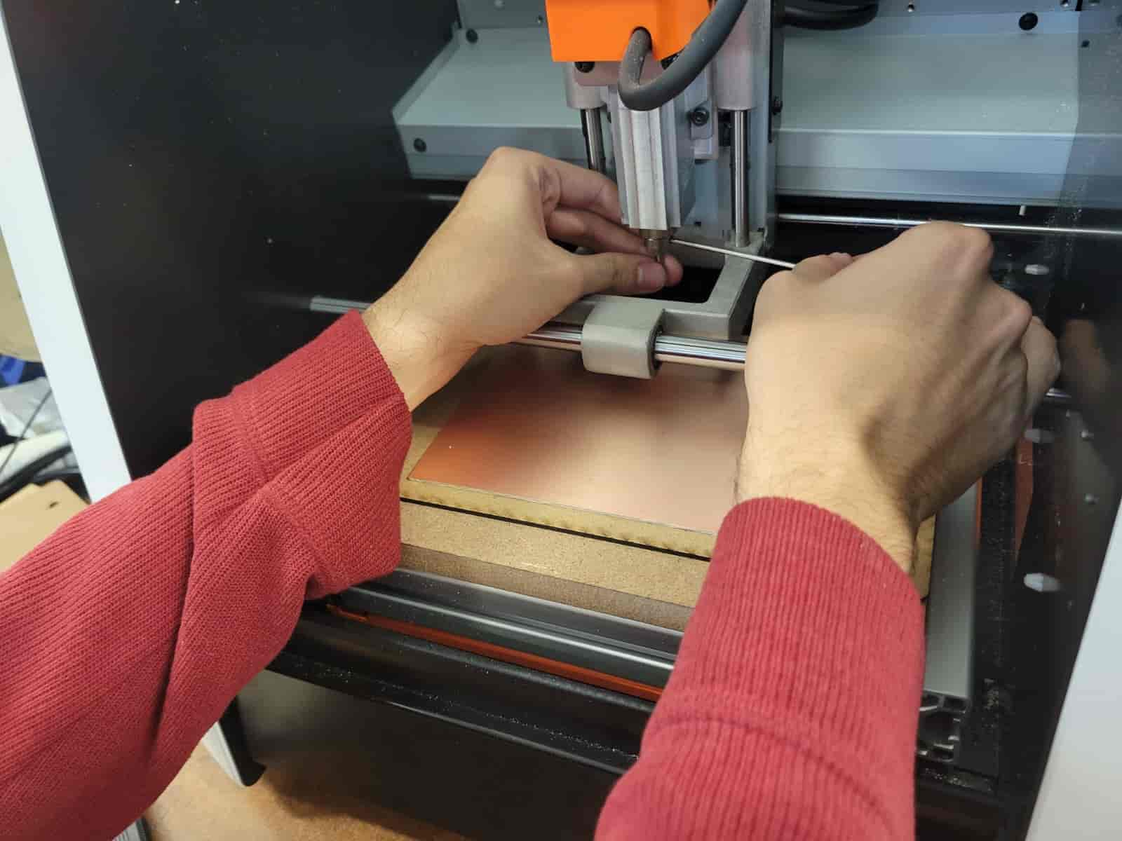
6.5 Set Origin Point
This part is either lots of fun or an absolute tedium, depending on your patience. The x and y axes are pretty easy, we just have to move the toolhead so that the tool is positioned as close to us as possible on the left corner of the FR-4 plate, here we will select the "Set Origin Point X/Y" option. The z axis is an entirely different ordeal, we will first get close to the plate, being careful with the speed of descent, since descending too fast could lead us to smash the tool against the plate, potentially damaging or destroying it.
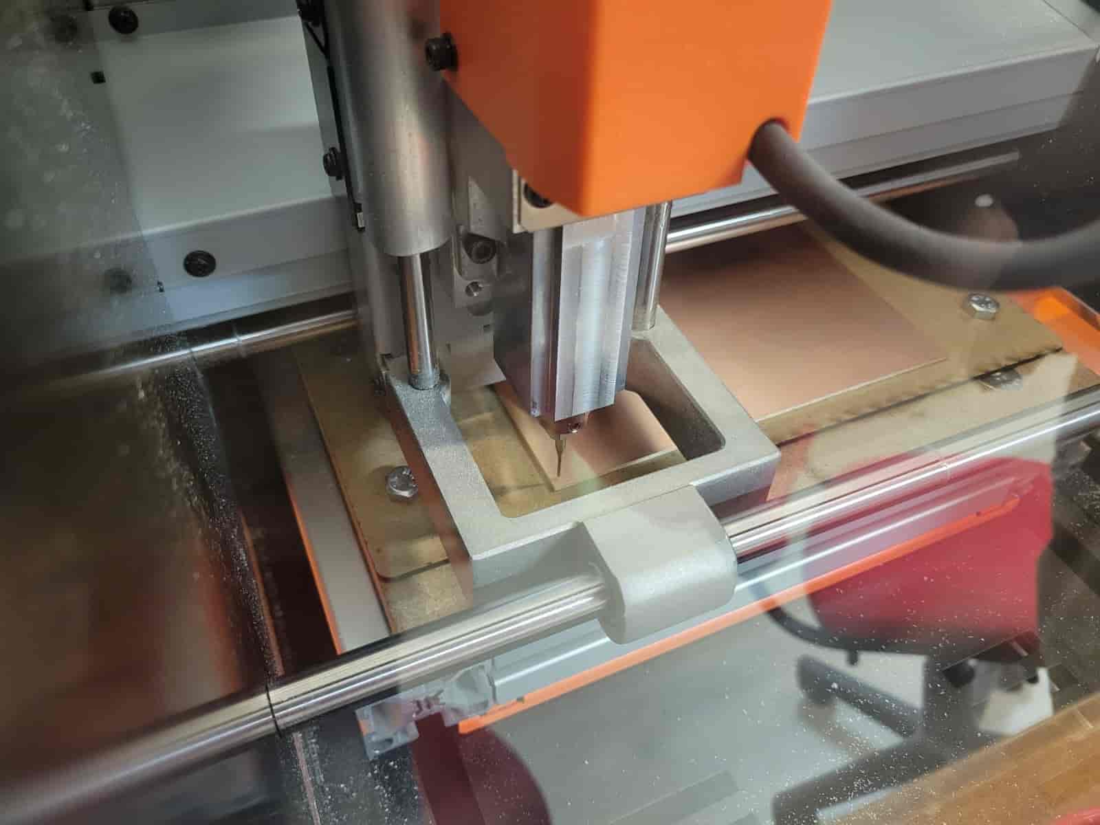
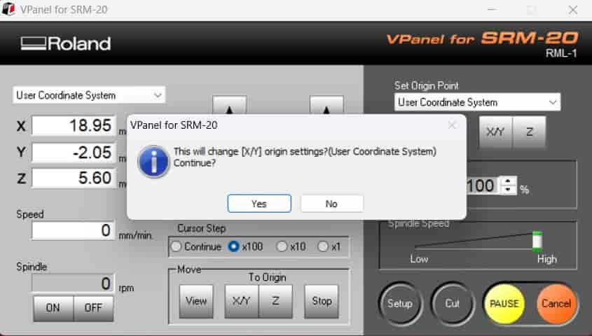
Once we are about 1 or 2 mm from the plate, we will close the cover and turn on the spindle, when the spindle gets to its max velocity, we will continue our gentle descent until it appears the tool has made contact with the plate, here, we will set our first Z-0 by selecting the "Set Origin Point Z" option.
We will raise the tool to observe if we have started penetrating the plate, If the plate remains intact, we will return to Z-0 and continue descending in steps, I repeat this process in 0.05 mm intervals until I see a hole form in the plate, this is where I will set my definitive origin point.
6.6 Hole Milling Process
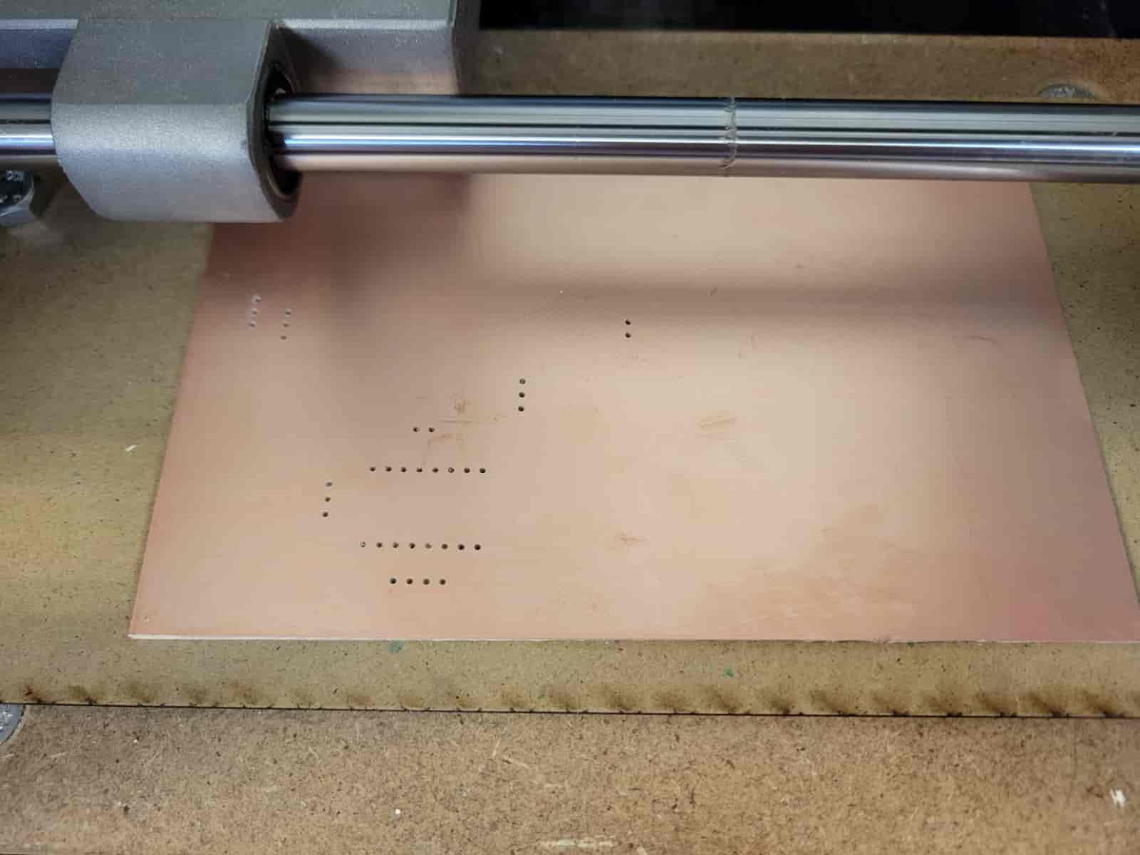
I raise the tool about 15 mm over the Z-0 coordinate and select the "Cut" option, here I load my file into the machine and press output.
The spindle will accelerate to its top speed and begin cutting the holes. It's very important to supervise the process in case anything goes wrong. You should be watching and listening carefully to the machine, you can tell something's wrong by the noise, which will become characteristically rough if anything's out of order.
6.7 Dust Extraction
As explained before, the fiberglass epoxy dust that is produced by the process is a health hazard that must be taken care of. When any process reaches its finish, we have to open the cover and extract the dust using a vacuum cleaner, after which we will use a small brush to remove any lodged particles, and we vacuum one last time.
6.8 Track Engraving Process
The cutting process for the tracks involves an entirely different tool, in my case I'm using a 10° V-Bit engraving cutter.
6.8.1 Change Tool
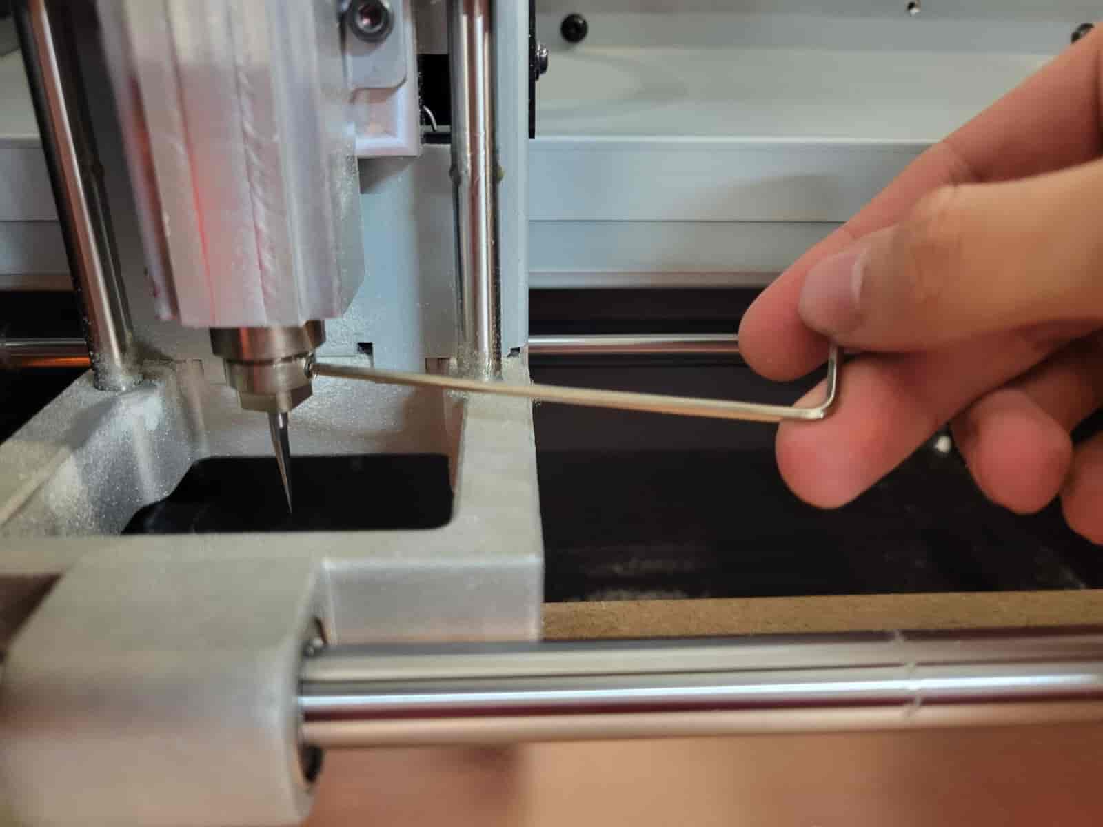
We remove the previous tool and install the V cutter in the same manner as the flat endmill.
6.8.2 Re establish Z-0
Since our tool is different in length, we have to repeat the process of establishing the Z-0 coordinate.
Once again, we descend carefully with the spindle on until we see the material is penetrated. For better clarity, I recommend moving the spindle one or two mm in the X or Y axes to dig a new hole for reference.
Once ready, we set the Z origin point, but do be careful not to change the X and Y origin points, since we need to keep all processes aligned in the X and Y axes.
6.8.3 Start Engraving Process
Once again, we raise the toolhead to a safe position, load the corresponding file and select output.
Just like before, we supervise the process carefully until it is finished.
6.8.4 Dust Extraction
Once finished, we vacuum the dust.
6.9 Outer Edges Milling Process
To cut the edges, we will be repeating the exact same process that we did with the holes.
6.9.1 Change Tool
We remove the V-Bit cutter and install the 0.8 mm flat endmill.
6.9.2 Re establish Z-0
Once again, we look for and set the origin point.
6.9.3 Start Milling Process
We load the file and begin the process.
COMPLICATION 1
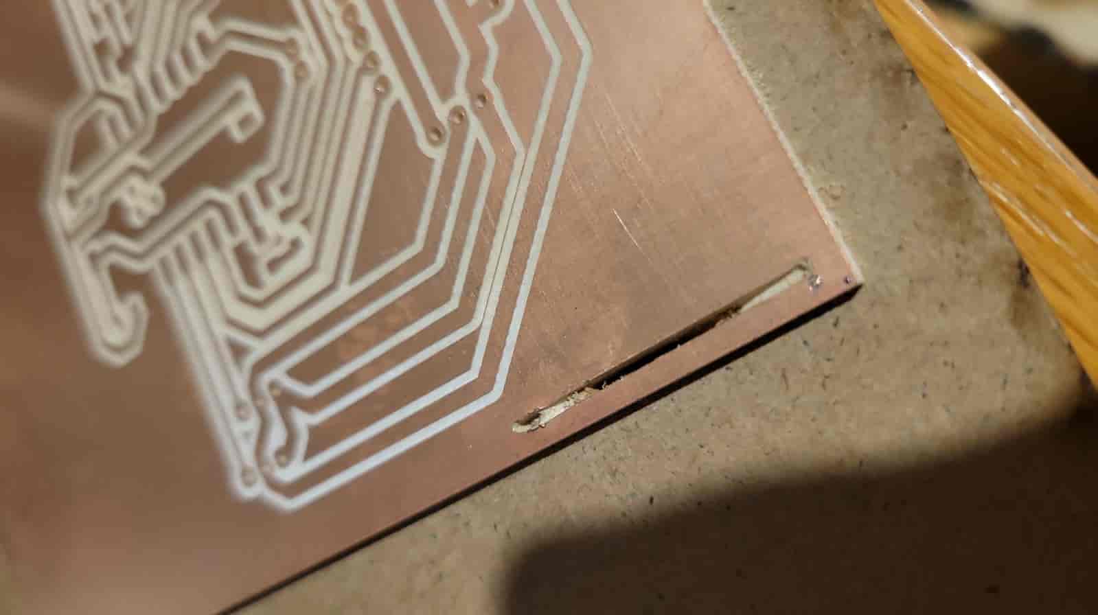
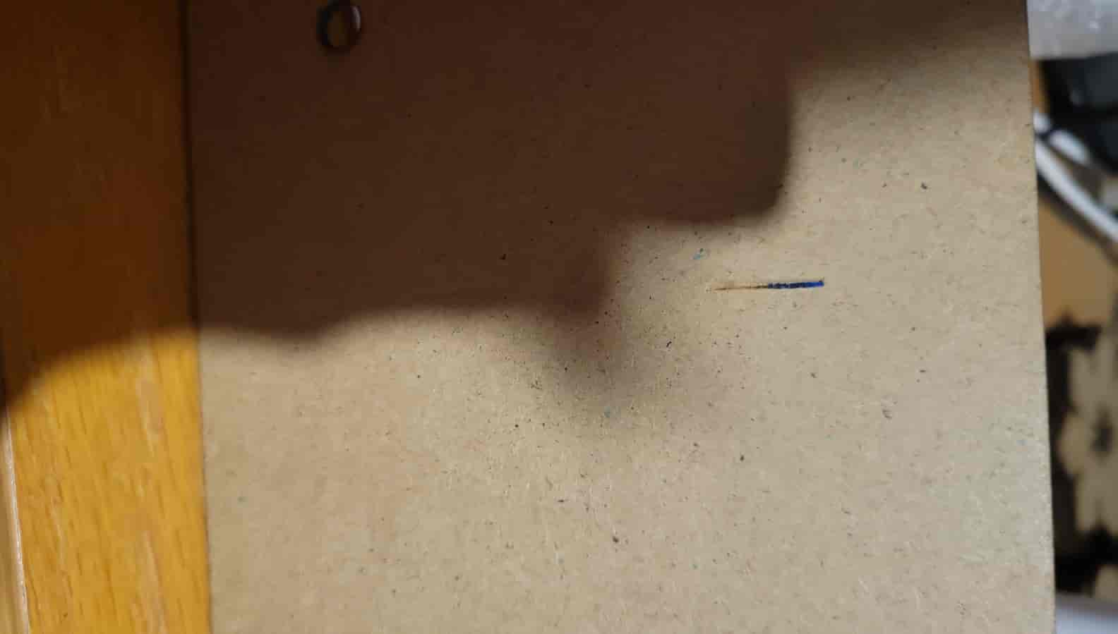
As I explained before, securing the tool tightly is of utmost importance. In my case, the tool was fastened well enough to stay in place under its own weight, but once the milling process began, vibrations caused it to loosen gradually. Eventually, it started descending while cutting, until it completely perforated the sacrificial board.
Fortunately, I noticed this quickly and stopped the process before the tool could be damaged. It was a close call, though. This is why its crucial to always supervise the process.
COMPLICATION 2
Since my lab was closing and I was already getting kicked out, I had to stop the milling process for the day. This led to a significant problem—when the machine is disconnected, the established origin points are erased, meaning I would have to carefully re-establish them later, as close to the originals as possible.
The next morning, I tackled this issue by manually setting the X-0 and Y-0 coordinates approximately over the hole left from the original zero position. Then, I set the Z-0 coordinate about 5 mm above the plate and started the process, allowing the tool to move over the already carved material. By repeating this process multiple times, I was able to realign the toolhead with the original zero coordinates to a surprisingly precise degree.
In the end, it looked as if nothing had ever happened.
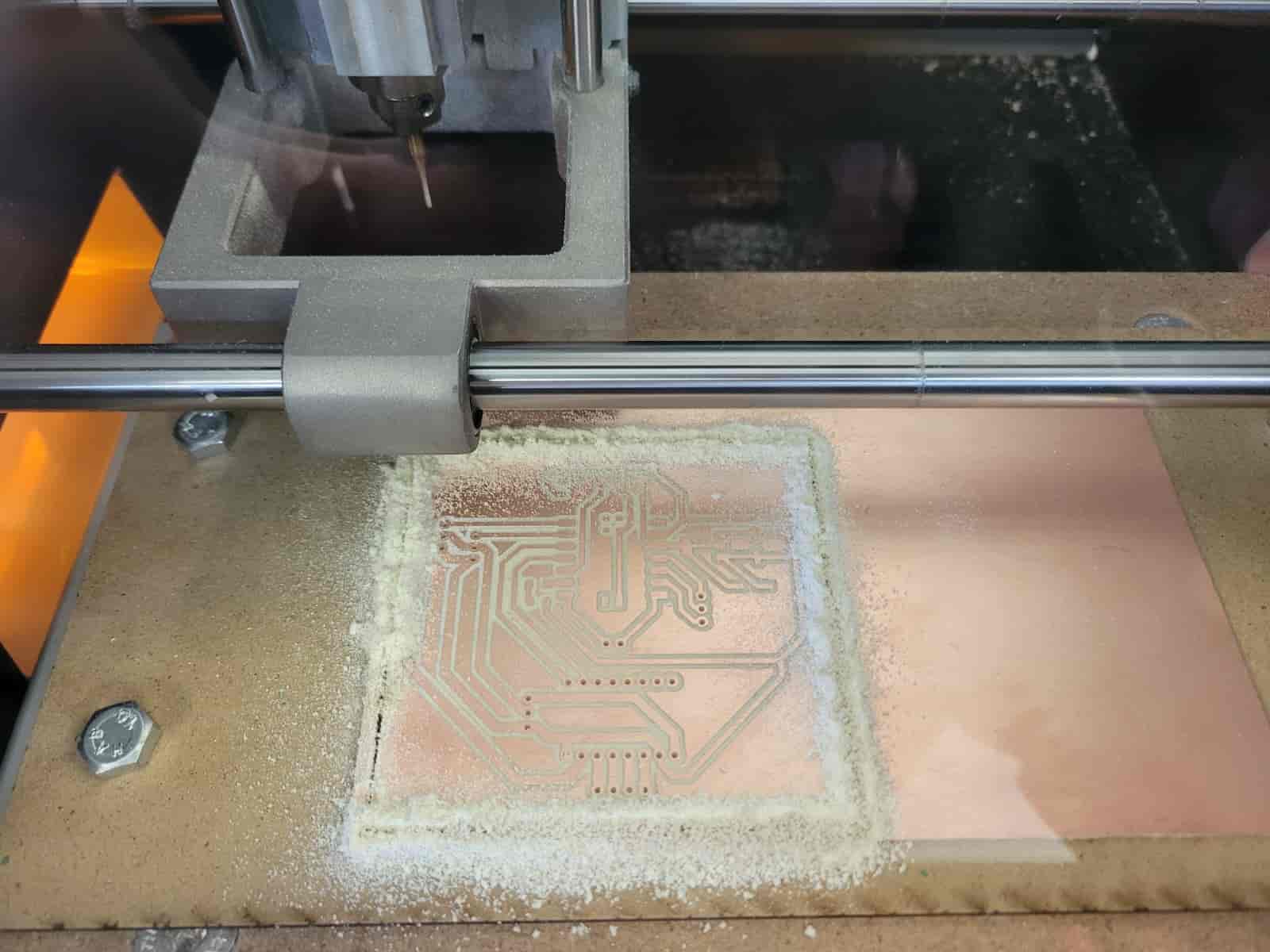
6.9.4 Resume Milling Process
Once the 0 coordinates were re established, I began the process once again, now having secured the tool as tightly as possible.
This time, everything went smoothly.
6.9.5 Dust Removal
Just like before, we vacuum all of the dust particles.
6.10 Final Product Extraction
We select the "View" option, which will move the machine bed towards us, allowing a better access. We remove the tool and store it with all the other tools in the small cabinet beneath the machine bed.
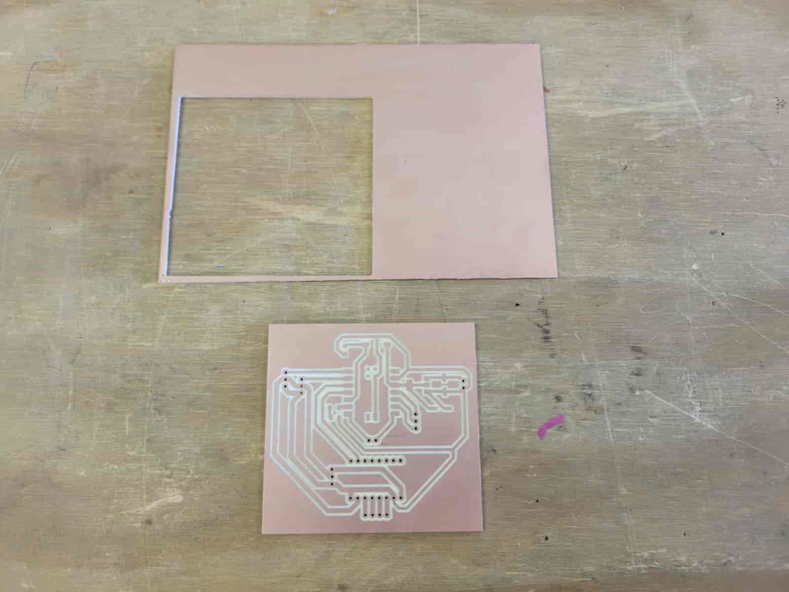
We then unscrew the sacrificial board and remove the remaining plate and PCB with the help of a spatula. We remove all of the double-sided adhesive tape. Finally, we turn off the machine.
Here are the results of the process:
7. Surface Mount Technology Soldering
Oh boy, we've arrived at the bane of anyone with shaky hands—a group I, unfortunately, belong to.
Surface Mount Technology is a method used to assemble electronic circuits by mounting components directly onto the surface of a PCB. Unlike through-hole soldering, which requires drilling holes for component leads, SMT improves space efficiency, reduces weight, and enables automated assembly.
The process consists of the following steps:
- Preparing the PCB and Components - We identify the placement of Surface Mount Devices or SMDs by referring to the board layout.
- Solder Paste Application - We apply solder paste onto a component's pad, using a syringe or other fine tools, this requires steady hands and good control.
- Apply Solder to Pad - Using a fine-tip soldering iron and soldering wire, heat the pad and apply a small amount of solder to one side.
- Component Placement - Using tweezers, carefully position the component onto the soldered pad and secure one of its sides.
- Hand Soldering - Once the component is lightly secured, reheat the soldered point to make small adjustments for better alignment. Once properly positioned, solder the opposite side to fully secure the component. Repeat for all remaining components.
- Inspection and Testing - Gently scrub the board with isopropyl alcohol to remove flux residue. Conduct a visual inspection, checking for misaligned components, solder bridges, or cold joints. A multimeter can also be used to verify connectivity.
I followed this process starting with my smaller components, these being my resistors and LED, then I followed with the components on the center of my PCB and kept going outwards. This order allows us to have better maneuverability with the soldering iron.
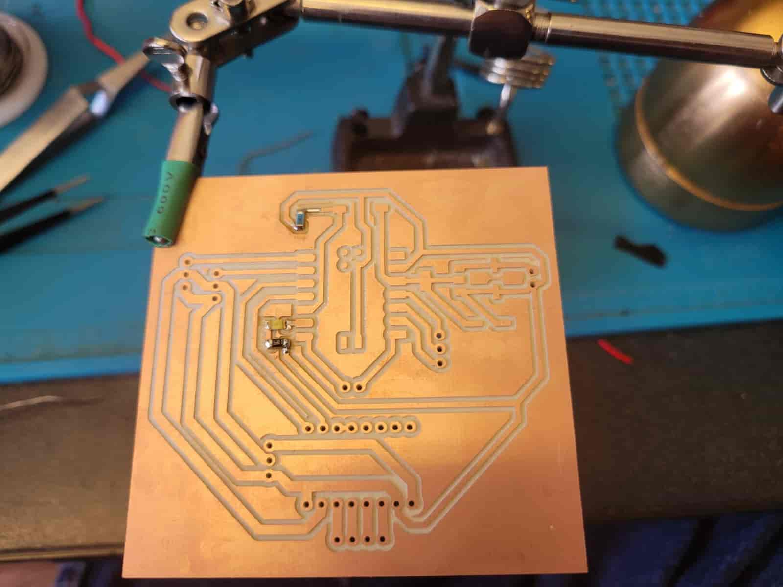
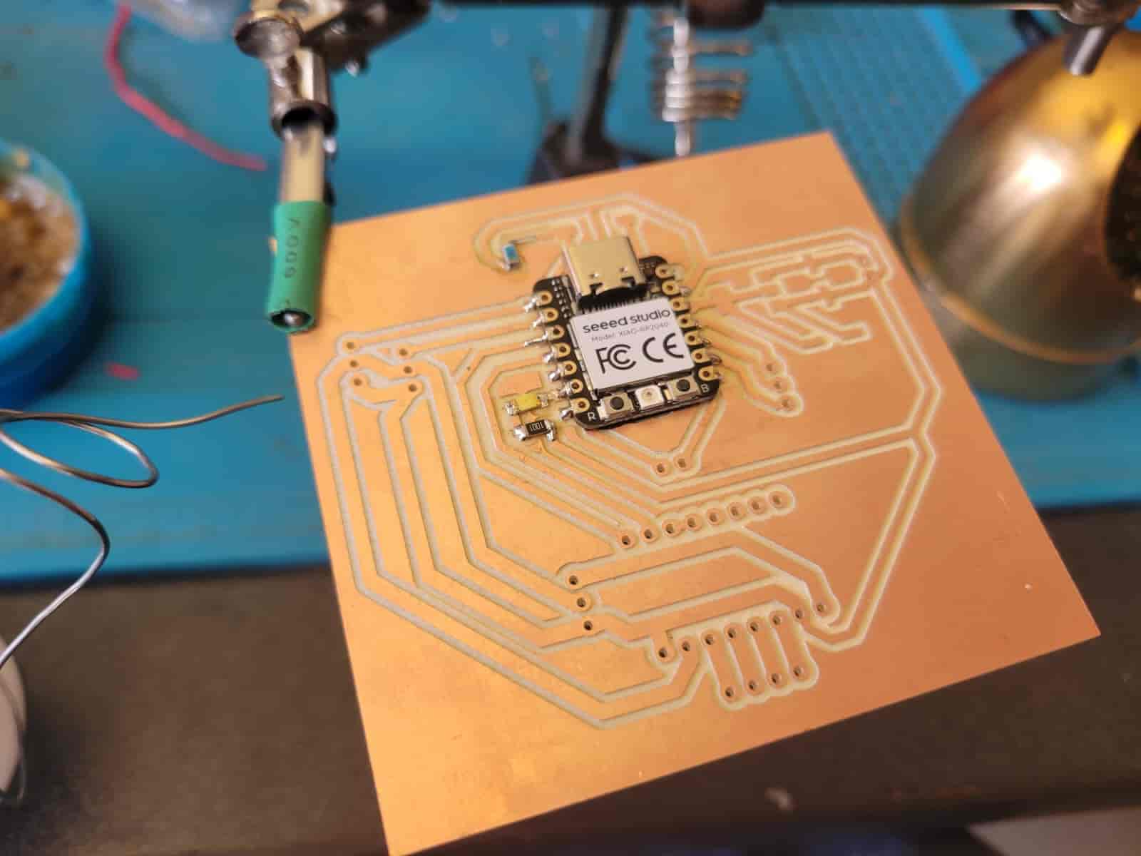
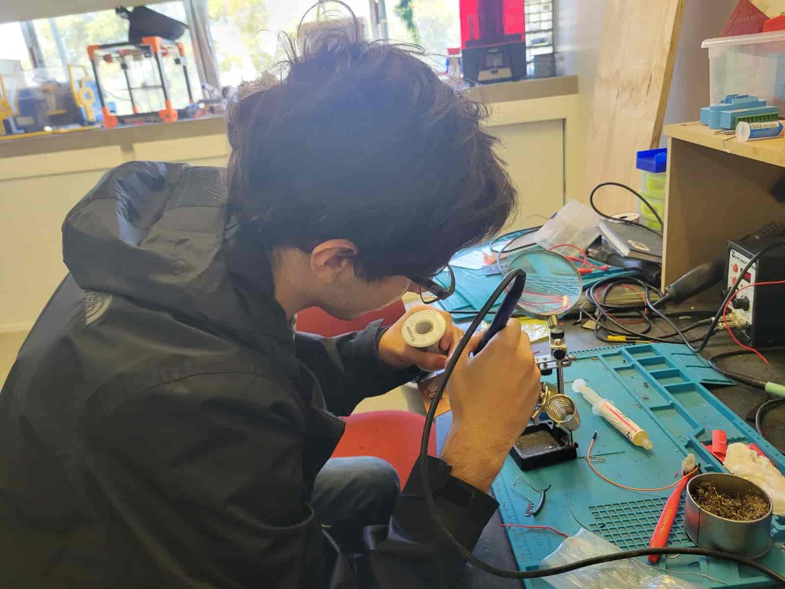
One thing worth noting is that the LED is a diode, which has a specific polarity, the ground side is the one with a minute square, though I confirmed this by using a multimeter.
For my pins, I inserted them trough the back of the PCB and soldered one to fix it in place, then I re-heated it to allign it perpendicularly to the PCB. Once aligned, I soldered all remaining pins.
For the A4988, it actually stuck to the PCB by sheer pressure on the pins, making soldering it surprisingly easy.
COMPLICATION 3
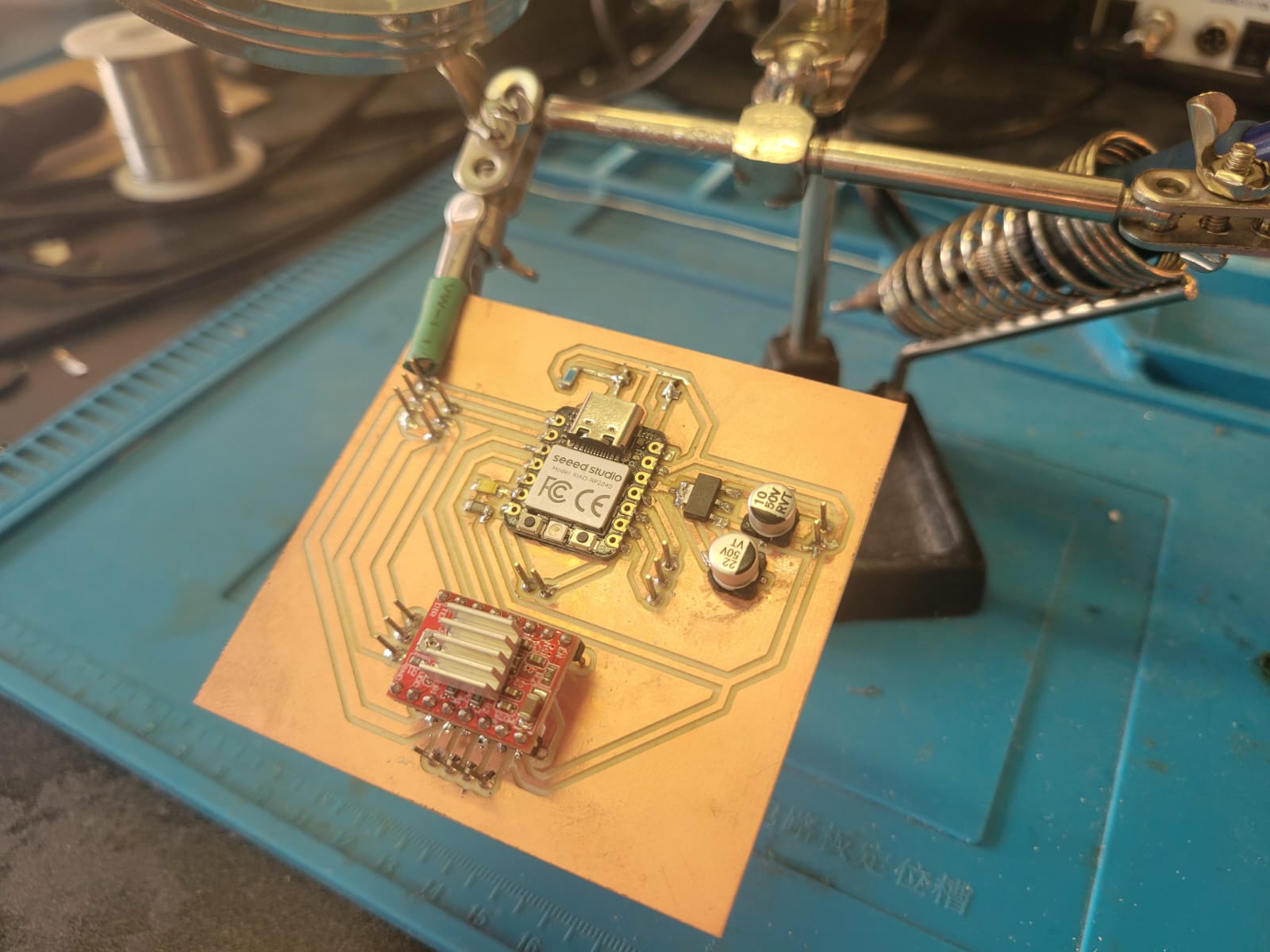
As I foreshadowed earlier, I failed to notice that the push button overlapped with the Type-C cable—until the very end of the process, no less.
Once I identified the problem, I consulted my friend Apolo for possible solutions. Together, we came up with the idea of a "tactical button"—by cutting two holes on the other side of the PCB and linking both sides with cut pins, we could flip the button to the opposite side.
To execute this, I asked my senior Max for one of his drill bits, we fired up the Dremel Workstation, and carefully cut the holes. I then inserted the pins, soldered the top side, trimmed the pins on the underside as short as possible, and finally soldered the button into place.
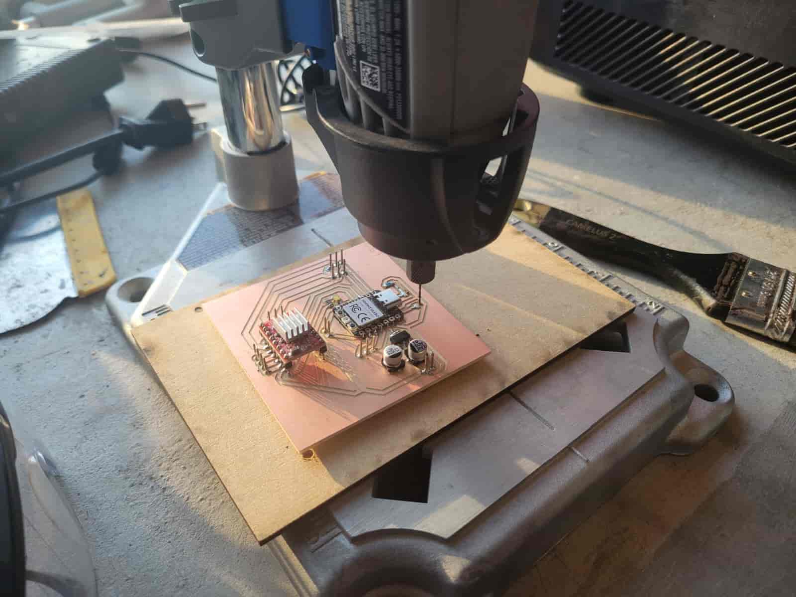
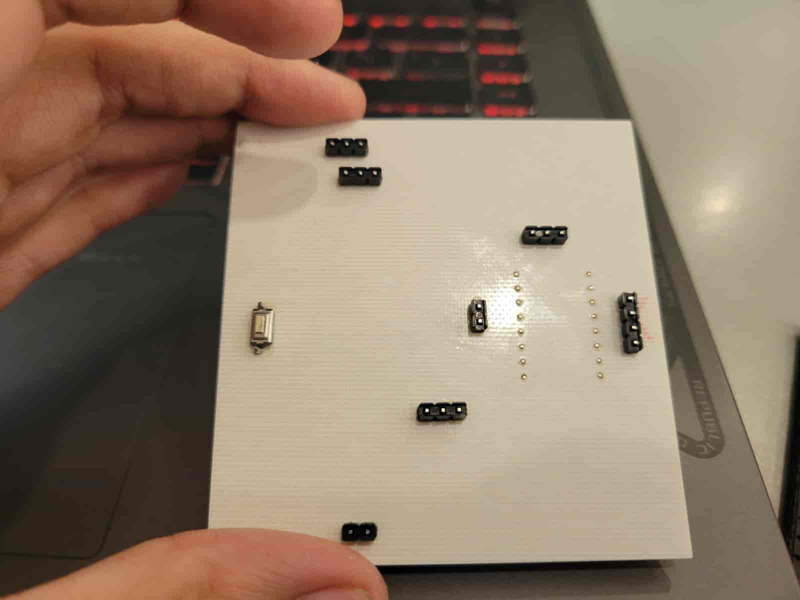
This solution worked perfectly—and honestly, it looks pretty cool. It's not real through-hole technology, so please don't crucify me, my Fab Academy overlords. With this, my PCB was officially complete, the last step is loading a program to check its functionality.
8. PCB Testing
I decided to conduct a small test, using the button and the LED.
I connected the XIAO to my computer and booted up the Arduino IDE and installed the library for the XIAO RP2040, which you can find here.
I wrote this simple code that would turn on the LED while the button was pressed:
#define LED_PIN  D5
#define BUTTON_PIN D4

void setup() {
    pinMode(LED_PIN, OUTPUT);
    pinMode(BUTTON_PIN, INPUT);
}

void loop() {
   	if (digitalRead(BUTTON_PIN) == HIGH) {
        digitalWrite(LED_PIN, HIGH);
   	} else {
        digitalWrite(LED_PIN, LOW);
    }
}
Now, for the moment ot truth:
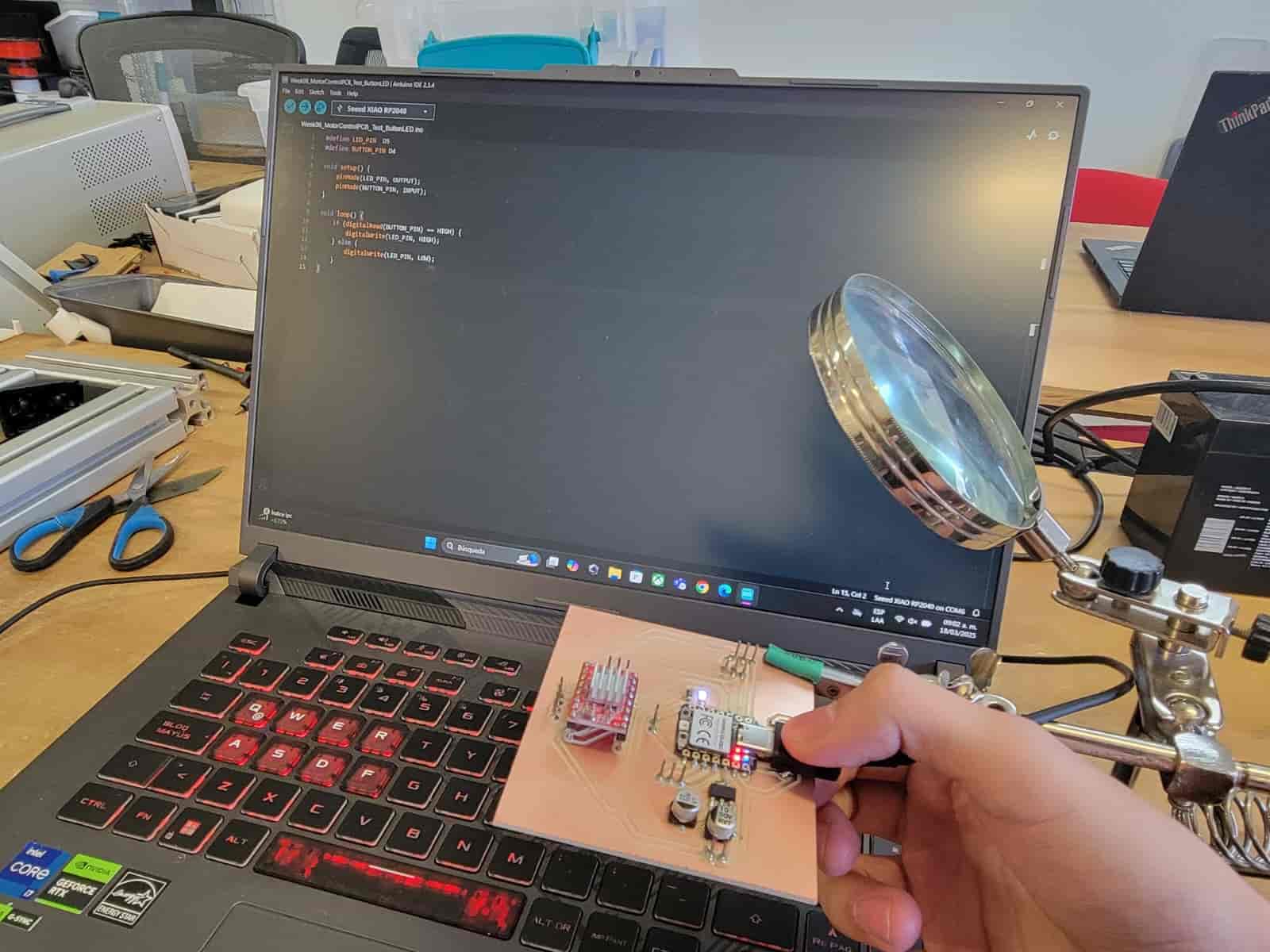
It works! You cannot fathom how happy I am, but we can take it further, now I will test the board's motor control capabilities.
I asked ChatGPT to assit me in writing a code that would allow me to control the motors through the serial monitor;
Prompt: I need you to help me add things to this code, I want to control two servos that are connected in the D0 and D1 pins in my XIAO, the D2 controls the DIR signal for my A4988 driver and the D3 controls the STEP. Please add code to control motors from the serial monitor
This is the code that was generated:
#include <Servo.h>

// Pin Definitions
#define LED_PIN   D5
#define BUTTON_PIN D4
#define SERVO_1_PIN D0
#define SERVO_2_PIN D1
#define DIR_PIN  D2
#define STEP_PIN D3

// Servo Objects
Servo servo1;
Servo servo2;

void setup() {
    // Pin Modes
    pinMode(LED_PIN, OUTPUT);
    pinMode(BUTTON_PIN, INPUT);
    pinMode(DIR_PIN, OUTPUT);
    pinMode(STEP_PIN, OUTPUT);

    // Attach Servos
    servo1.attach(SERVO_1_PIN);
    servo2.attach(SERVO_2_PIN);

    // Initialize Serial Monitor
    Serial.begin(115200);
    Serial.println("System Ready. Use commands: S1 angle | S2 angle | M direction steps");
}

void loop() {
    // LED Control with Button
    if (digitalRead(BUTTON_PIN) == HIGH) {
        digitalWrite(LED_PIN, HIGH);
    } else {
        digitalWrite(LED_PIN, LOW);
    }

    // Check for Serial Commands
    if (Serial.available()) {
        String command = Serial.readStringUntil('\n');
        command.trim();

        // Servo 1 Command (e.g., "S1 90")
        if (command.startsWith("S1")) {
            int angle = command.substring(3).toInt();
            angle = constrain(angle, 0, 180); // Limit range
            servo1.write(angle);
            Serial.print("Servo 1 moved to ");
            Serial.print(angle);
            Serial.println(" degrees");
        }

        // Servo 2 Command (e.g., "S2 45")
        else if (command.startsWith("S2")) {
            int angle = command.substring(3).toInt();
            angle = constrain(angle, 0, 180);
            servo2.write(angle);
            Serial.print("Servo 2 moved to ");
            Serial.print(angle);
            Serial.println(" degrees");
        }

        // Stepper Motor Command (e.g., "M 1 200")
        else if (command.startsWith("M")) {
            int spaceIndex1 = command.indexOf(' ');
            int spaceIndex2 = command.lastIndexOf(' ');

            if (spaceIndex1 > 0 && spaceIndex2 > spaceIndex1) {
                int direction = command.substring(spaceIndex1 + 1, spaceIndex2).toInt();
                int steps = command.substring(spaceIndex2 + 1).toInt();

                digitalWrite(DIR_PIN, direction > 0 ? HIGH : LOW);
                Serial.print("Stepper moving ");
                Serial.print(direction > 0 ? "forward" : "backward");
                Serial.print(" for ");
                Serial.print(steps);
                Serial.println(" steps");

                for (int i = 0; i < steps; i++) {
                    digitalWrite(STEP_PIN, HIGH);
                    delayMicroseconds(500);
                    digitalWrite(STEP_PIN, LOW);
                    delayMicroseconds(500);
                }
            }
        }
    }
}
Another great success.
9. Comments and Recommendations
I received a lot of help from my peer Apolo and my senior Maximo A. Figueroa Navarro, I want to thank them for their guidance during this week.
10. Learning Outcomes
This week was pretty packed, I learned how to manufacture a PCB, solder surface-mount devices and practice improvisation skills. The final product feels like a great achievement, and it takes me a step closer to my final project goals.
I will learn from the complications that arrised this week and take the correct meassures in the future to avoid them.
Files
- LED and Button Test Arduino code
- Motor Test Arduino code
- Motor Control PCB SVG files
- Motor Control KiCad files
