03. Computer Controlled Cutting
Summary
For this week's assignment, I developed a laser cut parametric construction kit accounting for the lasercutter kerf, which can be assembled in multiple ways, and a vinil cut out.
I will explain in detail the tools I used and the process I followed to complete the assignment.
1. What is Computer Controlled Cutting?
Computer Controlled Cutting is a process used in an immense variety of projects and industries. It involves the digital design of an 2D or 3D object, which is then exported through special software as code that can be read by a machine. This machine can be a laser cutter, a vinyl cutter, a CNC milling or routing machine or any other machine that can be controlled by a computer.
The type of code that is generated depends on the machines and the software used. For example, a laser cutter uses vector files, while a CNC machine uses G-code. In both cases, the machine reads the code that tells it how to move and cut the material. This is a very useful process because it allows for the creation of complex and precise designs that would be impossible to make by hand.
2. What is Parametric Design?
Parametric design is a way of designing a project through the use of parameters; mathematical values that determine the design characteristics of one or many objects. We can parameterize the dimensions, angles and patterns of a part or assembly, allowing us to easily control and modify the properties of an object by simply changing the numeric values and equations in our parameters.
3. Parametric Construction Kit Design
From the get go, I decided to develop the construction kit in the SolidWorks CAD software. Let's go over the process shall we?
Investigation and Inspiration
Initially I was somewhat lost on how I should design my parts, having trouble deciding the general shapes and sizes. For inspiration, I took a look at some of the designs from Fab Academy 2024, among which Riichiro Yamamoto's , from Fab Lab Barcelona, stood out as particularly impressive.
Inspired by his week 3 assignment's octagon shaped cardboard parametric construction kit, I decided to begin my design with a hexagonal shape.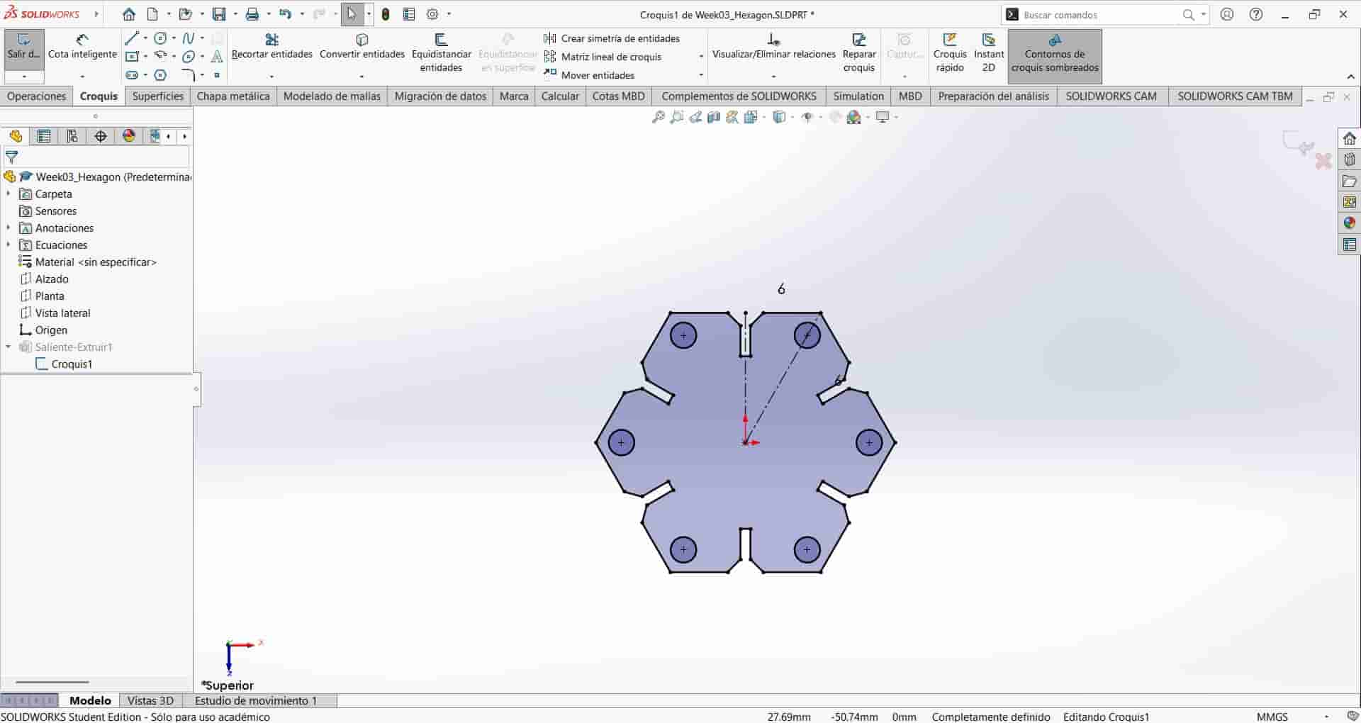
Parameter Creation
To set up and use our parameters, we have to follow the next steps:
Opening the Equations manager
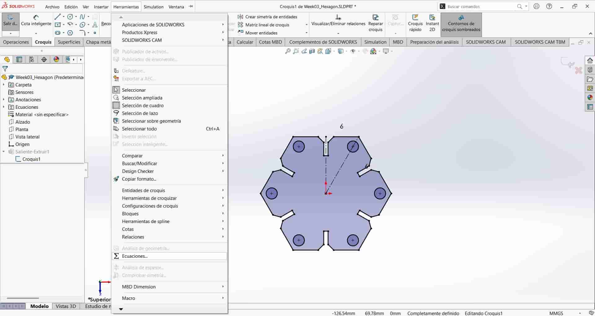
Start a new part document in SolidWorks and place your cursor over the SolidWorks logo on the top left corner of the UI, this will display a small menu to the right. Now move your cursor to the Tools option, this will display the tools menu, where we will find the Equations option near the bottom, clicking on this option will display the Equations manager.
Creating a Global Equation
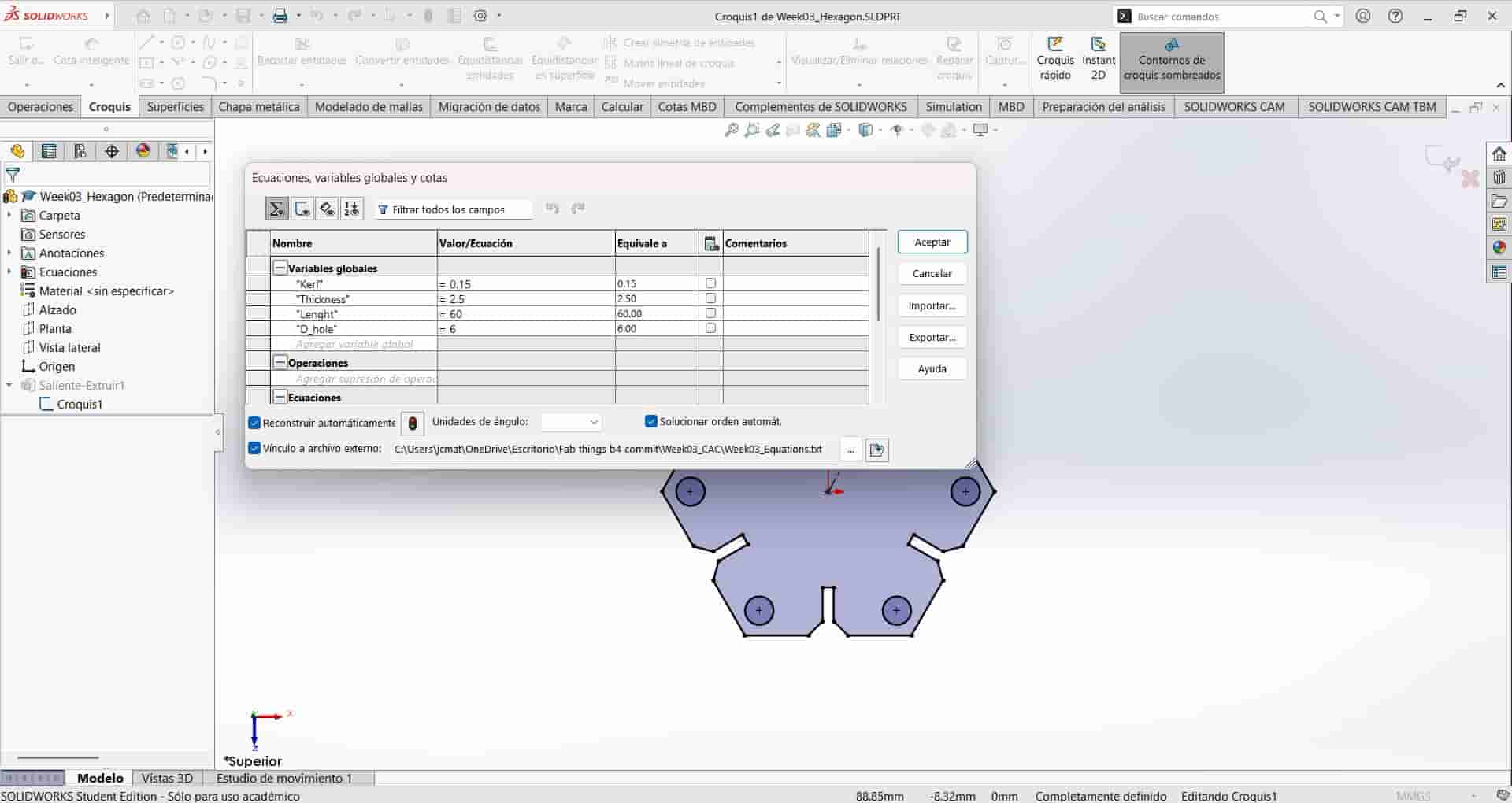
In the Equations manager, you can see the global equations table, this is where we are going to input our parameters. We start in the name column, here we will input the name of our variable, which should be short and easily identifiable. After writing the name, press enter to move on to the variable/equations column.
In the variable/equations column, we input the mathematical values and equations that will determine our variable, you can also define a variable by integrating a previous variable, for example, if we have the "length" variable and we want to create a "height" variable that is always double the length, when we determine the height variable we would input "length/2" in the values column and press enter.
The third column displays the final value of the equation, going back to the previous example; if the "length" variable was equal to 20 mm, then the final value of the "height" variable would be 10 mm.
After inputing all the necessary variables, click on the accept option on the right side of the equations manager.Creating the Necessary Variables
For my first design, I created four different variables, one accounting for the thickness of the material, which is 2.5 mm thick MDF, one for the side to side length, with a value of 60 mm, one for the diameter of the holes in the part, with a value of 6 mm and a variable accounting for the kerf of the laser cutter, which we calculated to be around 0.15 mm.
First Design Development
The first design I went for was the previously shown hexagon, with the thickness, length, hole diameter and kerf variables, I used the polygon tool to draw the hexagon and drew the lines for the top slot joint. I used the trim entities tool to eliminate the line connecting the top side, leaving the intended slot joint.
I drew one of the holes and construction lines to fix it in the right angle, finally I create two circular patterns to replicate the hole and slot joint six times each, and trim the excess lines as it was done with the first slot joint.
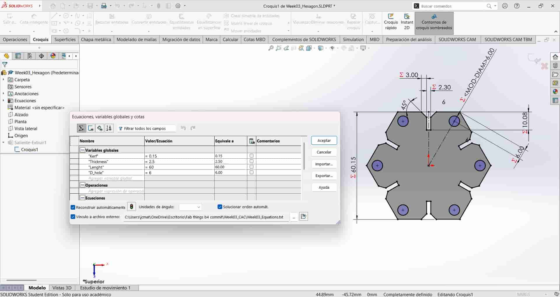
I proceed to input the dimensions of the drawn elements, but, instead of just writing the numeric values as usual, we insert equations related to our established parameters, always starting with "=", to establish a direct relationship between the equation and the dimension.
These equations are:- <"D1@Croquis1" = "Length" + "Kerf">: Determines the side to side length, with a value of 60.15 mm.
- <"D4@Croquis1" = "Length" / 6 + "Kerf" / 2>: Determines the depth of the slot joint, with a value of 10.08 mm.
- <"D3@Croquis1" = "Thickness" - "Kerf" - 0.05>: Determines the width of the slot joint, with a value of 2.30 mm.
- <"D5@Croquis1" = "Length" / 20>: Determines the length of the chamfer leading to the slot joint, with a value of 3.00 mm and a fixed angle of 45°.
- <"D7@Croquis1" = "Length" / 10>: Determines the distance between the holes and the pointed edges of the hexagon, with a value of 6.00 mm.
- <"D8@Croquis1" = "D_hole">: Determines the diameter of the holes, with a value of 6.00 mm.
- <"D1@Saliente-Extruir1" = "Thickness">: Determines the length of the extrusion, with a value of 3.00 mm
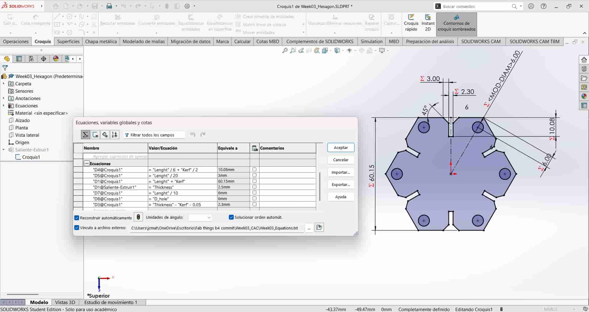
If inputed correctly, each parameterized dimension will begin with a "Σ", followed by a numeric value. Additionally, any changes made to the parameters in the equations manager will update the part in accordance with the new parameters.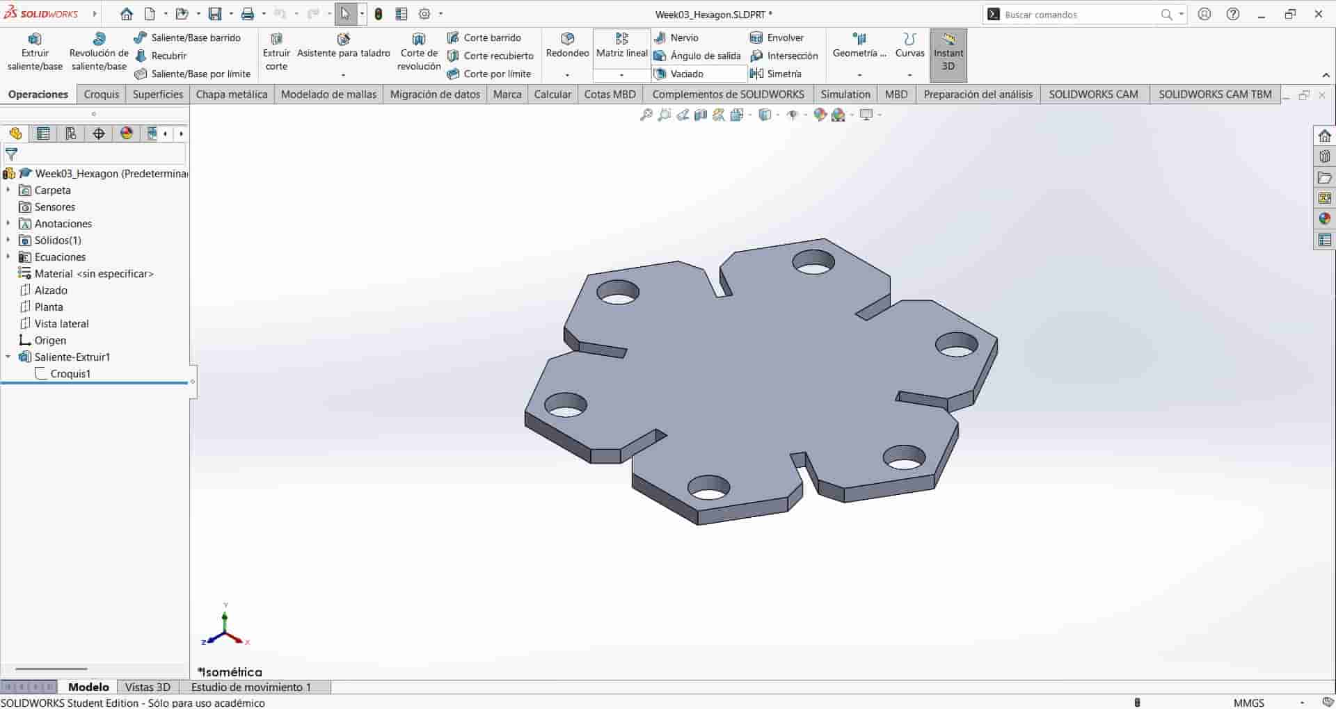
Second Design Development
After showing my progress to my local coordinator, he gave me the recommendation of making a part that could have a different number of sizes depending on the value of a single variable. I went with his recommendations and designed the part by following these steps:
New Part and Sketch
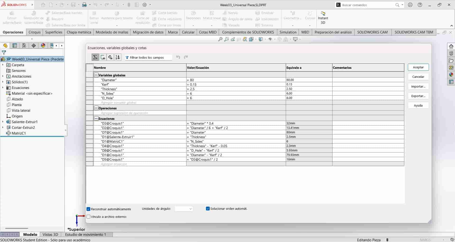
I created a new part, which we will call Universal Piece, and begin setting up our parameters:
- <Diameter>: 80 mm.
- <Kerf>: 1.5 mm.
- <Thickness>: 2.5 mm.
- <N_Sides>: 6.
- <D_hole>: 6 mm.
Sketch Design
- <"D1@Croquis1" = "Diameter" - "Kerf" / 2>: Determines the diameter of the greater circle, which corresponds to the maximum size of the part while accounting for kerf. The value is of 79.93 mm.
- <"D2@Croquis1" = "Diameter" / 6 + "Kerf" / 2>: Determines the depth of the slot joint, with a value of 13.41 mm.
- <"D3@Croquis1" = "Diameter" * 0.4>: Determines the horizontal distance between the edges of the sides, with a value of 32.00 mm.
- <"D5@Croquis1" = "D3@Croquis1" / 2>: Determines the length of the sides, with "D3@Croquis1" being in reference to the previous dimension, though, in retrospective, could be replaced by <= "Diameter" * 0.2>. The final value is 16.00 mm.
- <"D4@Croquis1" = "Thickness" - "Kerf" - 0.05>: Determines the width of the slot joint, this is the most important dimension for the parts to fit together, it's final value being 2.30 mm. This final value was determined after the inital tests, which we will go into detail later.
- <"D8@Croquis1" = "D_Hole" - "Kerf" / 2>: Determines the diameter of the lesser circle while accounting for kerf, with a value of 5.93 mm.
- <"D7@Croquis1" = "Diameter">: Determines the maximum distance of the extruded cut, ensuring that no matter the size of the part, the extruded cut operation would be succesfully executed. It's value is 80.00 mm
- <"D1@Saliente-Extruir1" = "Thickness">: Determines the size of the extrusion, equal to the thickness of the MDF sheet, which is 2.5 mm
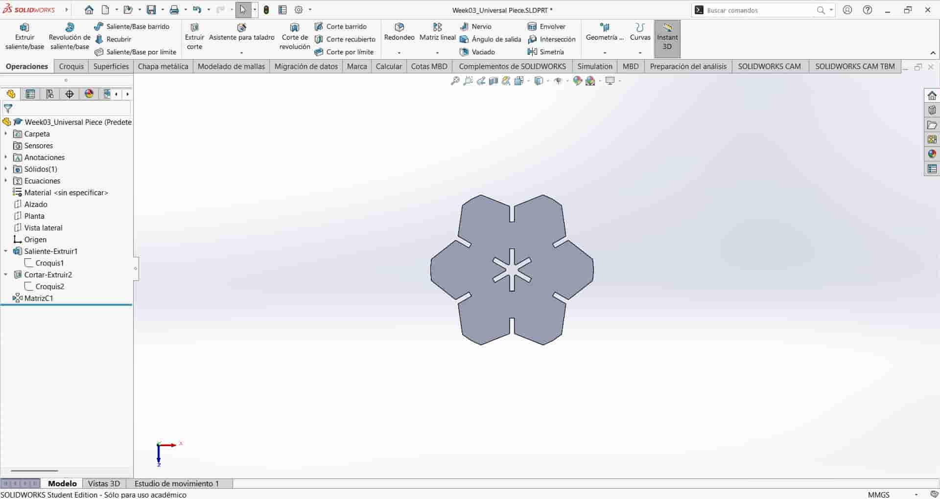
- <"D1@MatrizC1" = "N_Sides">: Determines the number of sides and slot joints of the part. This is the equation that will allow me to make different polygonal shapes stemming from this single hexagonal base. For this specific part its value is 6.
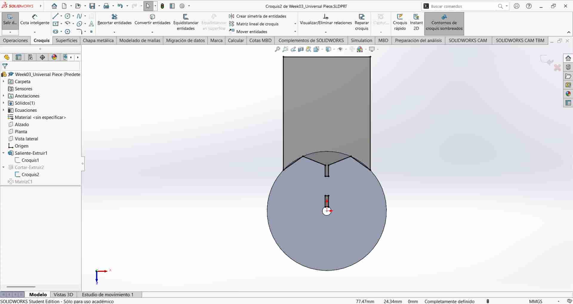
I create a new sketch and begin drawing, starting with two concentric circles, I then draw the lines that will become the sides and slot joint in construction mode, this is because instead of using an extrusion to give shape to our part, we will create a second sketch and use an extruded cut, substracting material from the circle. I also add dimensional equations and geometrical relations between the different elements, keeping symmetry in the sketch.
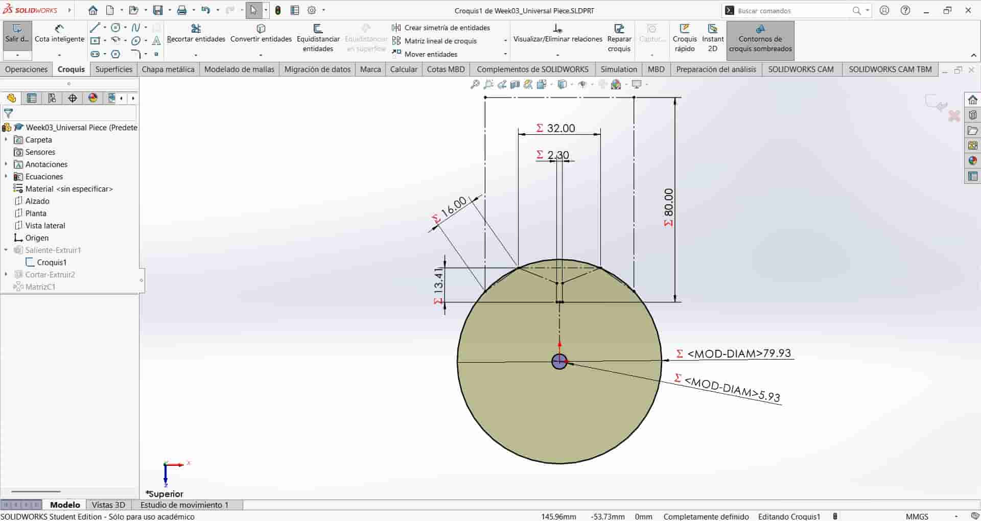
The equations that I employed were the following: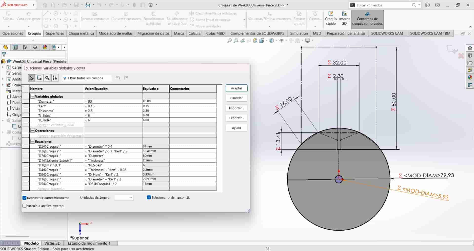 I extruded the first sketch in accordance with the "D1@Saliente-Extruir1" equation stated above, after which I make a new sketch on top of the extruded surface. In this sketch I transformed the features that we drew as construction lines in sketch 1 into normal lines, maintaining the exact same dimensions and geometrical relations, with the only new addition being the slot equal to the original slot joint, but now stemming from the smaller circle.
We create an extruded cut with the second sketch and in the "Through all" direction, substracting material and leaving us with the desired shape. The final step is to replicate the cut in a circular pattern.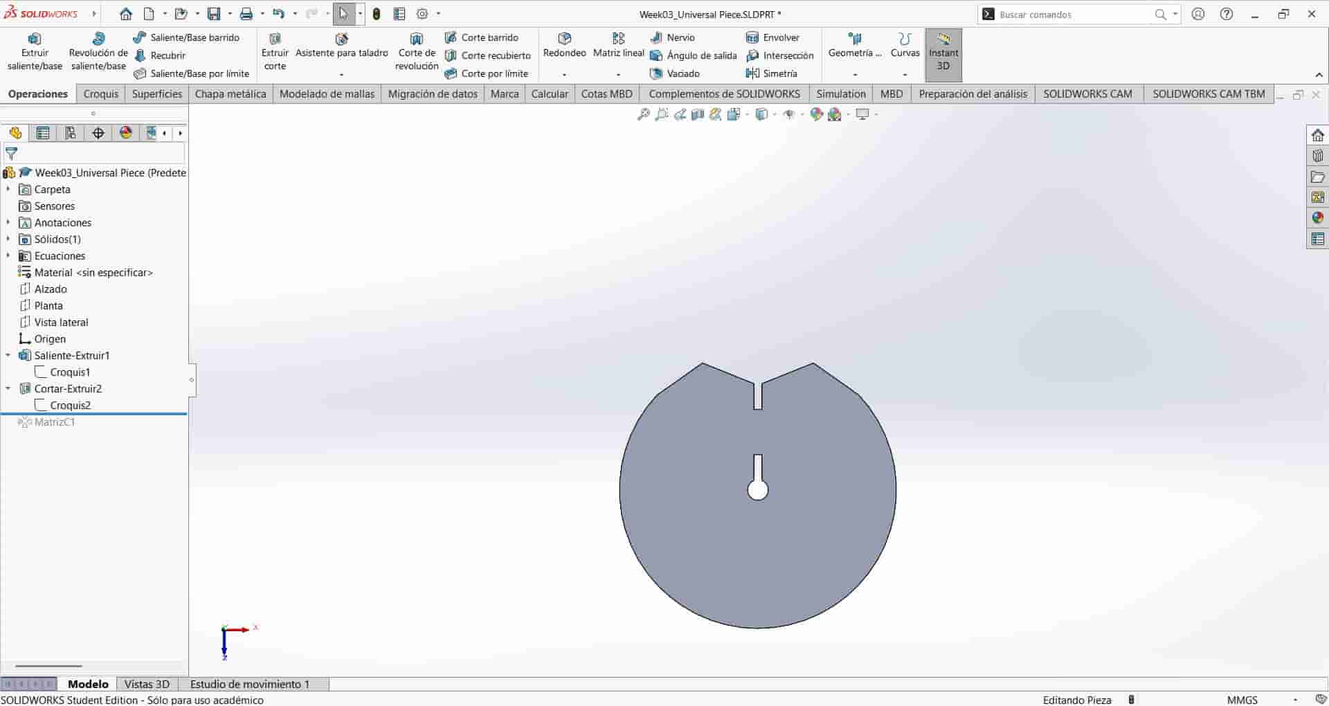 We select the circular pattern tool and click on the edge of the circle to determine the pattern's direction and select the extruded cut as the operation to be replicated.
We input the "= N_sides" equation in the number of instances section, this will replicate the number of cuts as explained above, leaving us with the final results.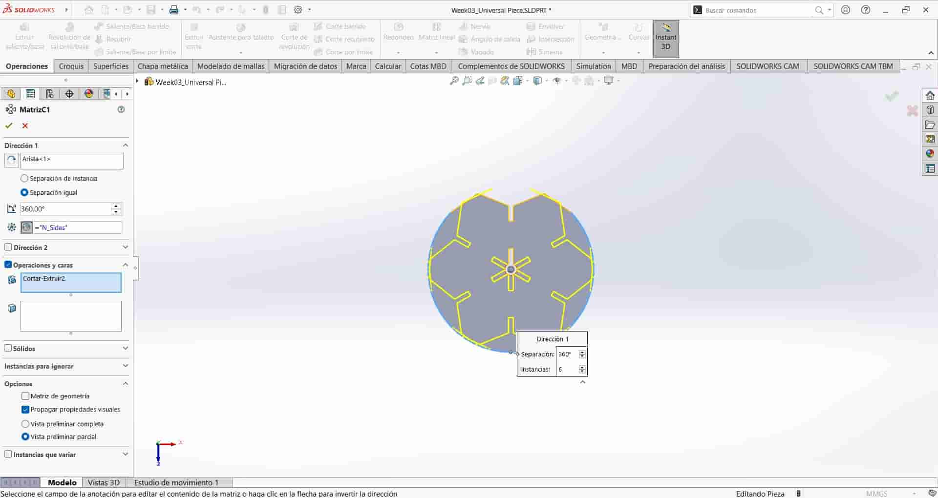
4. Assembly and Drawing
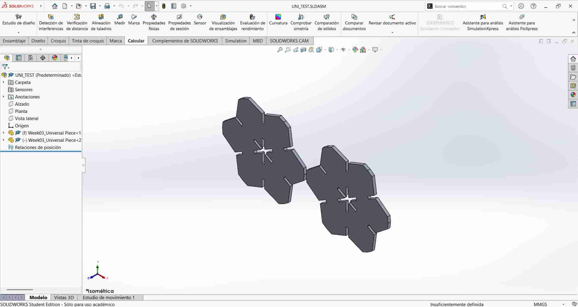
Once I was finished designing the parts, I created an assembly document and imported two Universal Pieces. I constrained them to be parallel and close to each other.
I proceed to create a new drawing type document, which we haven't taken a look into up to now. Let's figure it out together, shall we?
SolidWorks Drawing
New document
We create a new drawing and select the size and format of the sheets, I'm going with an A0 ISO since it offers the most space out of the available default formats.
Insert view
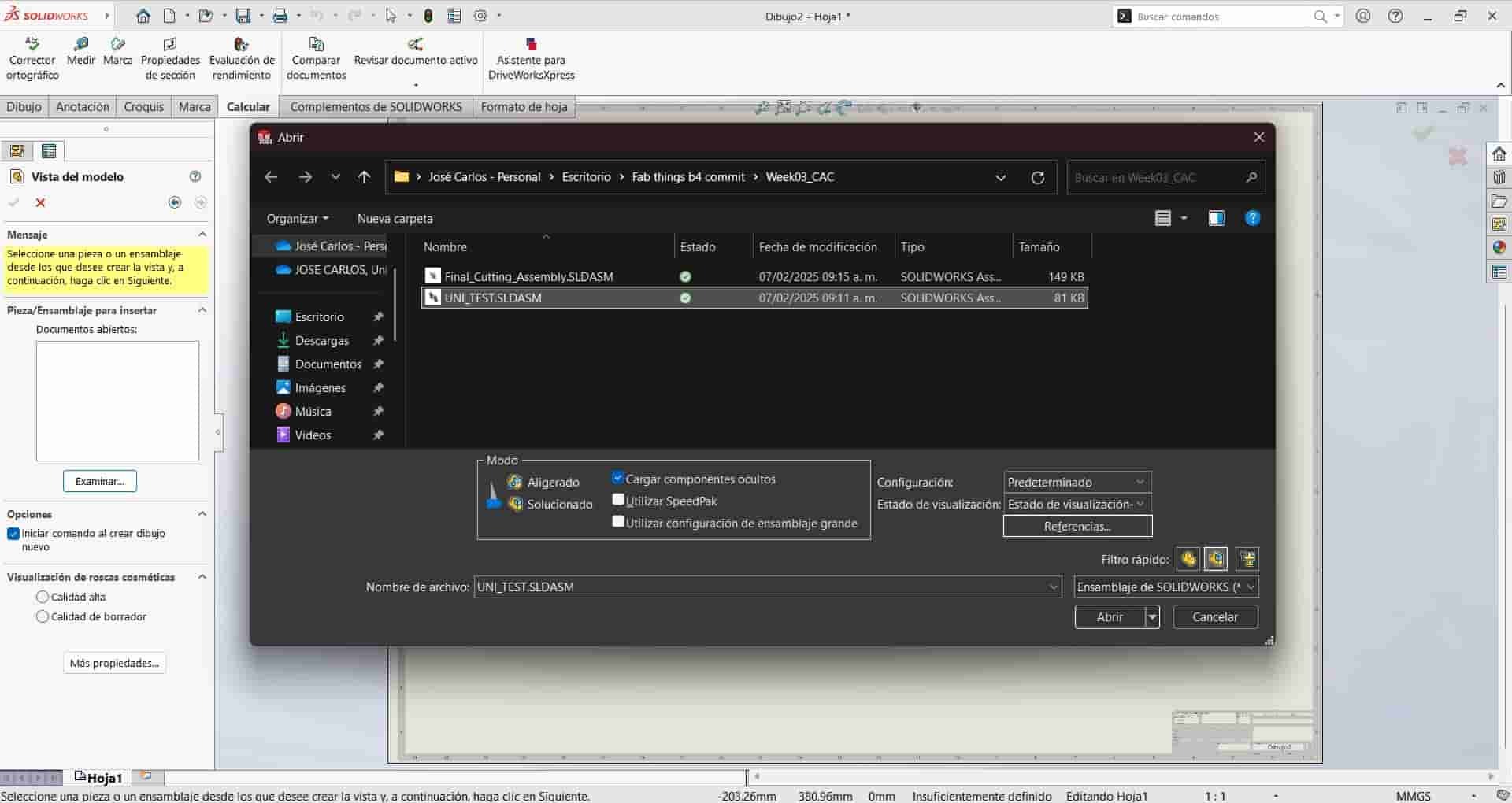
Once we have selected our sheet size, the view layout tab will open in the left side of the screen, click on the examine option, and select the file you want to import into the drawing, in our case, our testing assembly.
Drawing documents maintain a link to the imported files, so any change made to the design will be updated in the drawing.View customization
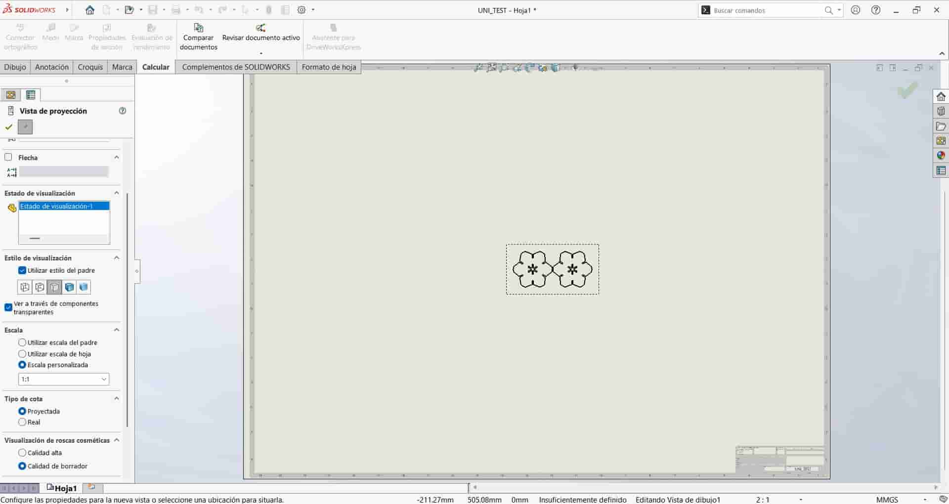
The view layout tab will display a variety of customization options for the view, in our case, we want to select a front view of our assembly and a 1:1 scale. Once finished click on the checkmark on the top right corner of the graphics area.
Format Deletion and View Placement
Click on the arrow next to Sheet 1 on the feature manager tree on the left side on the screen, this will display all the existing elements inside the sheet. Right click on the sheet format option and delete it, leaving only the view of the assembly. This is important because every single line and curve in the sheet will carry on to the subsequent documents that we will be handling, and into the final cutting pattern.
Drag the view into the lower right corner of the sheet.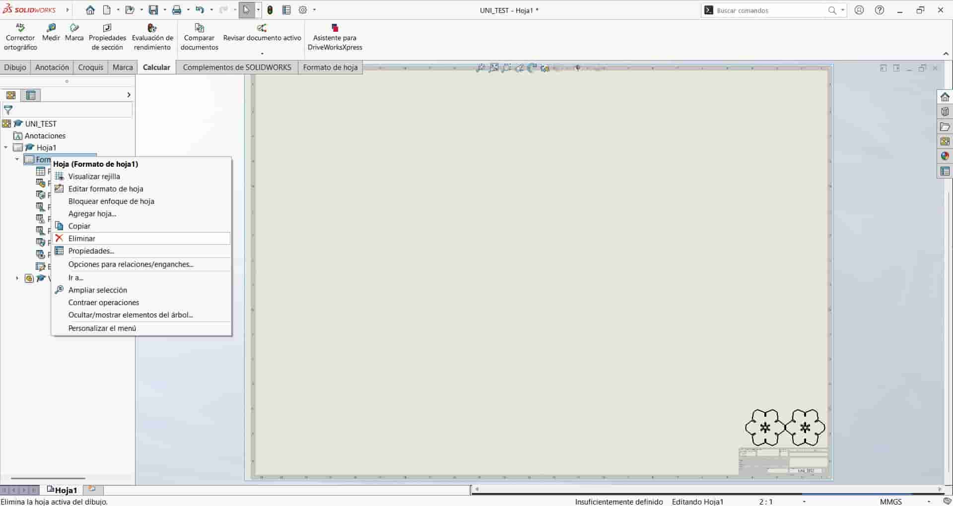
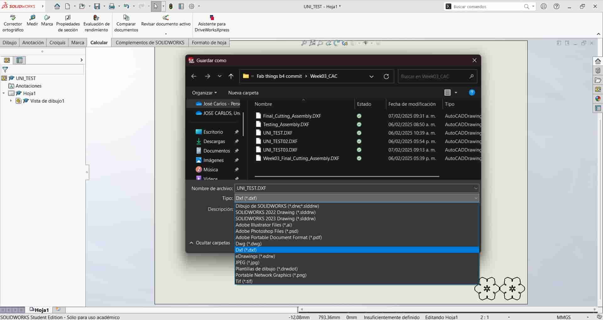
DXF export
Save your drawing file in case you need to make modifications later, then save it as a .dxf file. Dxf files are the type that we will use in the laser cutting program.
5. Smart Carve
Smart Carve is a piece of propietary laser control software developed by Han's Yueming Laser, used for operating laser cutting machines.
This software operates in a curious way, requiring a special USB licence key for starting and using the program.
The steps that I followed to use this software were the following:
Downloading and operating the Installer
Our local instructor gave us the link to download the installer.
Now, it is imperative to follow your instructor's indications while operating the installer, since our version had some sections written completely in Chinese.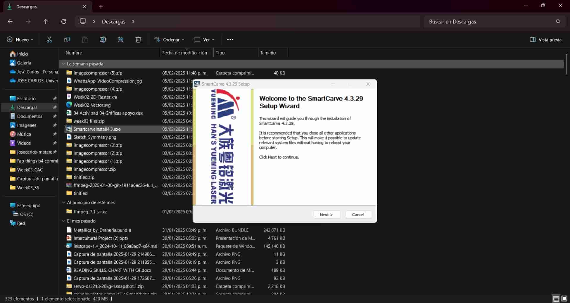
One of the most important steps in the instalation is selecting the correct language and the type of system.
Our laser cutter is of the 5th normal system, as displayed in this image: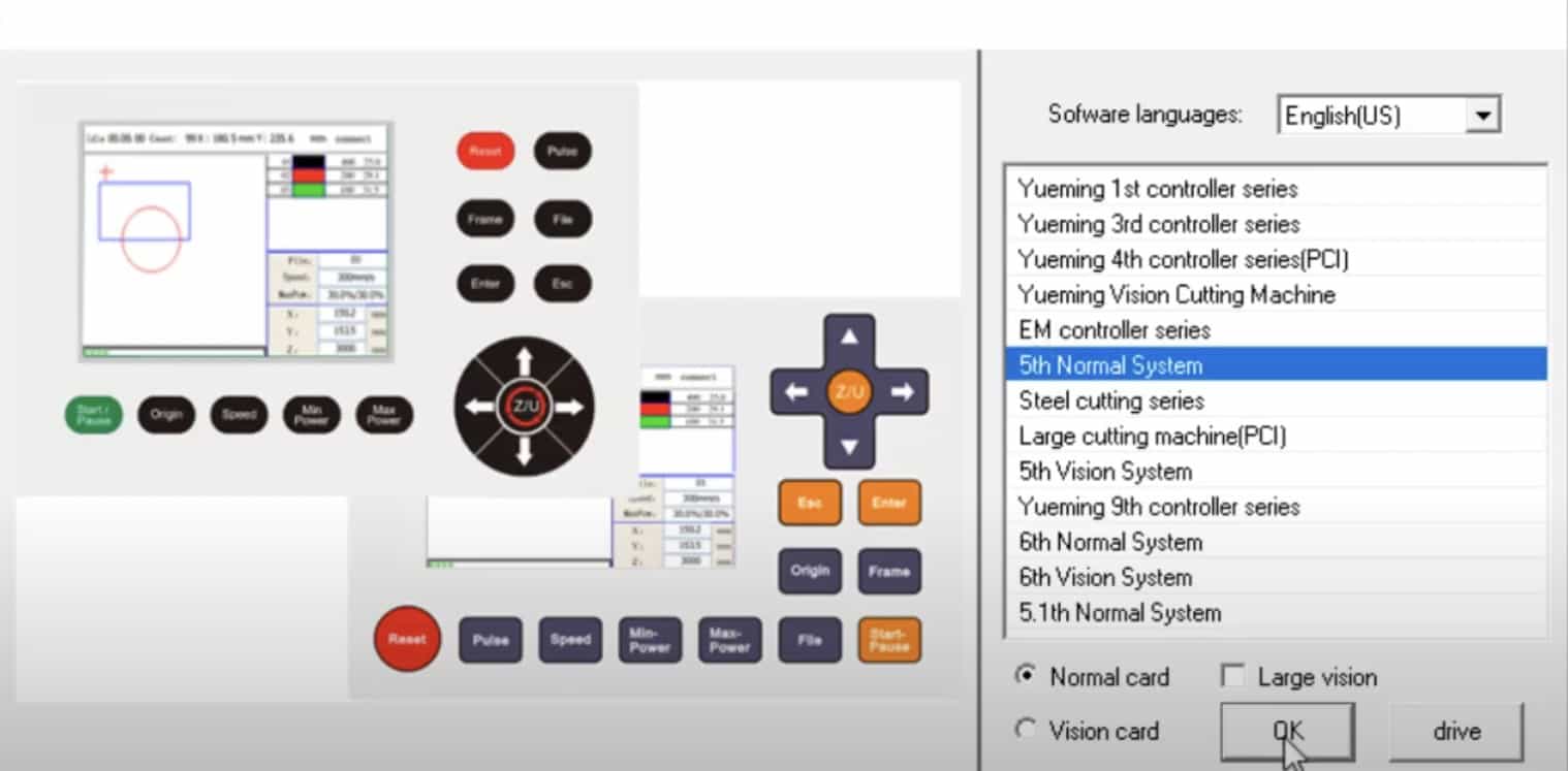
Let me emphasize that the instalation process will depend on the version of your machine and the installer you downloaded, so again, follow your instructors indications.Licence Key
Once correctly installed, we will require the USB licence key, although, from my understanding, the licence of the program is managed in a variety of ways, depending on the version of the software.
Request the licence key from your instructor and take good care of it, it may look modest but it is an important and expensive piece of equipment. When plugged into your computer you will be able to start the software.Import File
When we start the program, we will see the file option in the top left corner of our screen, selecting this option will display the file menu, where we will click on the import option.
We will now import the .dxf file that we created from our drawing.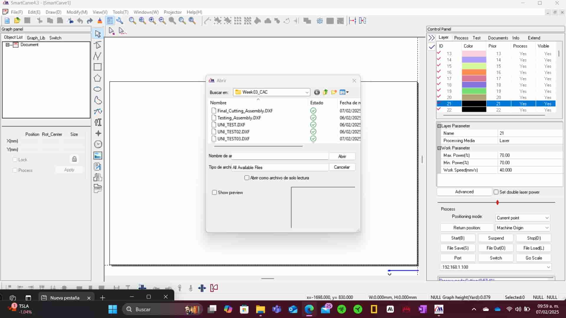
Once imported, the drawing will align itself with the default origin point in the program, in our case being the bottom right corner.Input Laser Parameters
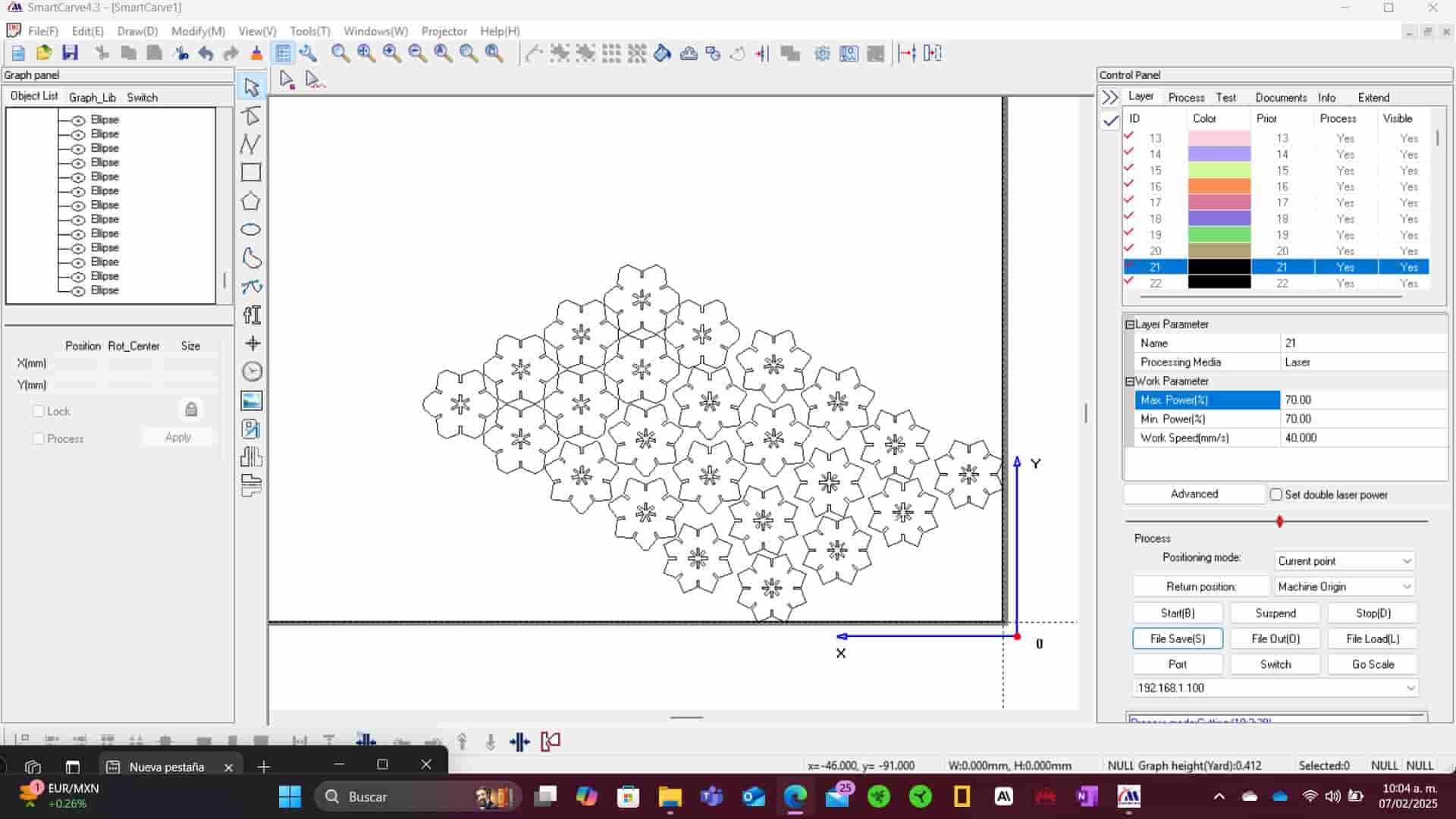
Select all the elements of the drawing, on the right side of the screen you will see the control panel. Here we will select the same color as the one in the drawing, in this case being black.
Once the color is selected, input the maximum and minimum laser power and work speed of the laser. We obtained these values with the tests conducted as part of our group assignment with the purpose of determining the correct balance of power and speed that will give us the fastest and cleanest cuts posible, while minimizing kerf. In our tests, we determined that the optimal combination of values range from 60 to 80 percent power and a speed of 40 to 60 mm/s.
I decided to go with 70% power and 40 mm/s speed, which, after testing, I was satisfied with. After setting my parameters I click on the apply button at the bottom of the graph panel, located on the left side of our screen.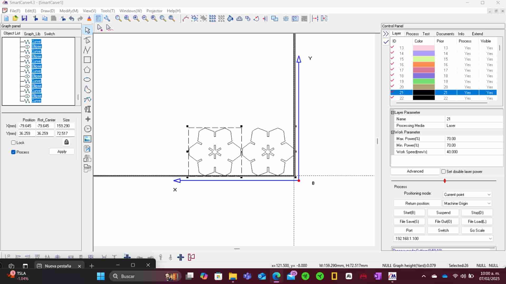
Save File
Once finished, we will click on the "file save(s)" button in the process section of the control panel. In the save menu, click on the generate OUD option and press ok.
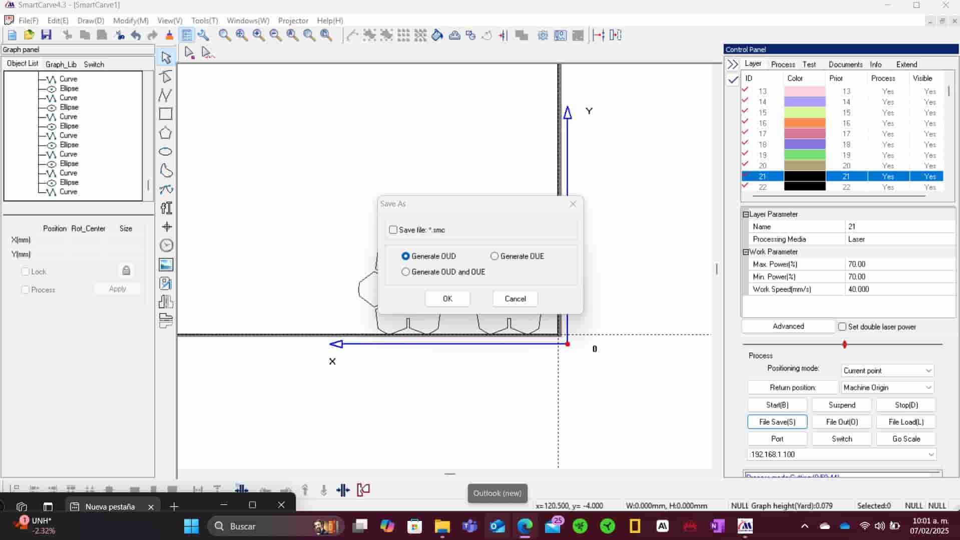
Now name your file and select where you want it to be saved.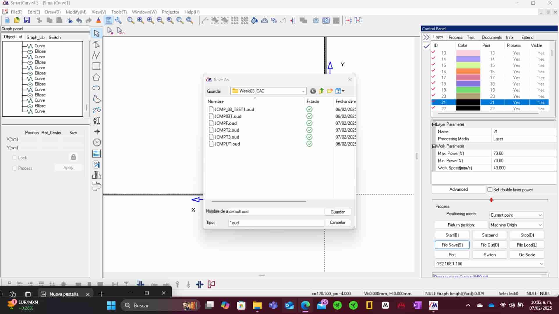
Remove Licence key
Once finished, close the program and remove the licence key from your device. Since we were given the licence key and the machine key together, we will hold onto them until we are finished using the machine, returning both to the instructor at the end of the process.
Store .oud file in your USB
Copy the .oud file into a USB drive.
6. Laser Cutter Activation
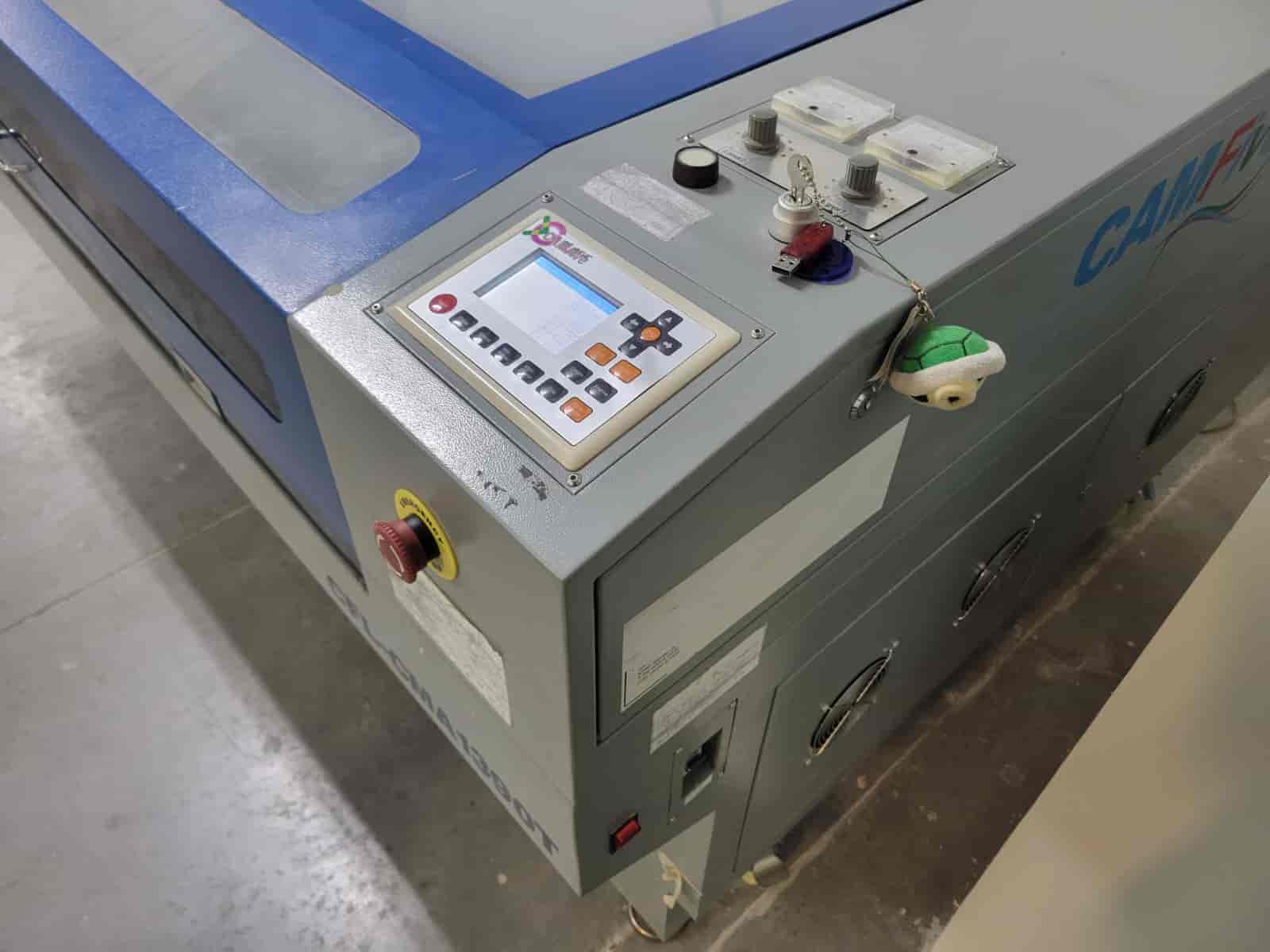
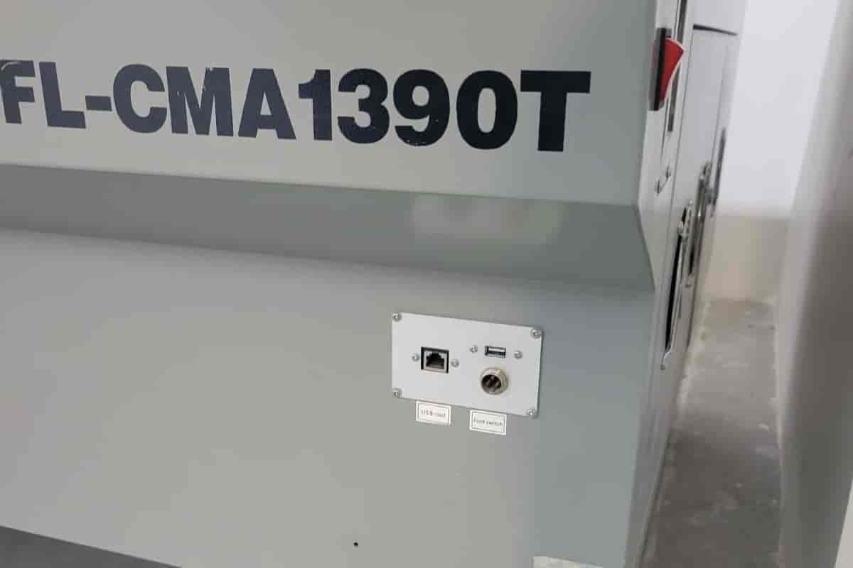
Fab Lab Puebla is equipped with three different CO2 laser cutters from the CAMFive brand. These machines are capable of cutting and engraving a variety of materials, such as medium-density fiberboard (MDF), acrylic, and cardboard. The machine that I used for this assignment is the CFL-CMA1390T, which has a working area of 1300 x 900 mm, a power output of 100 Watts and dual laser head system. For the full details you can check our group assignment here.
To use this machine we have to follow this process:
-
Registration and Key
As stated in section five, we were given the software licence key and machine key together, we will be using the machine key to operate the laser cutter. Before we begin working with the laser cutter, we have to register the time we start using the machine in the Fab Lab's log, along with our name, student id number, the department or course we are using the machine for, and the head of said department or course.
-
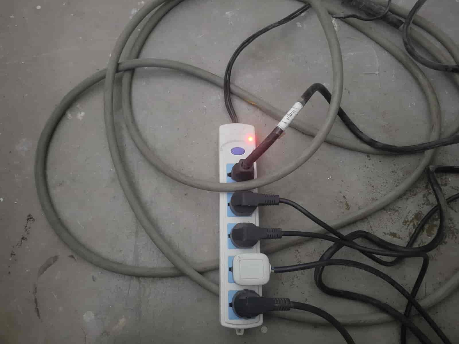
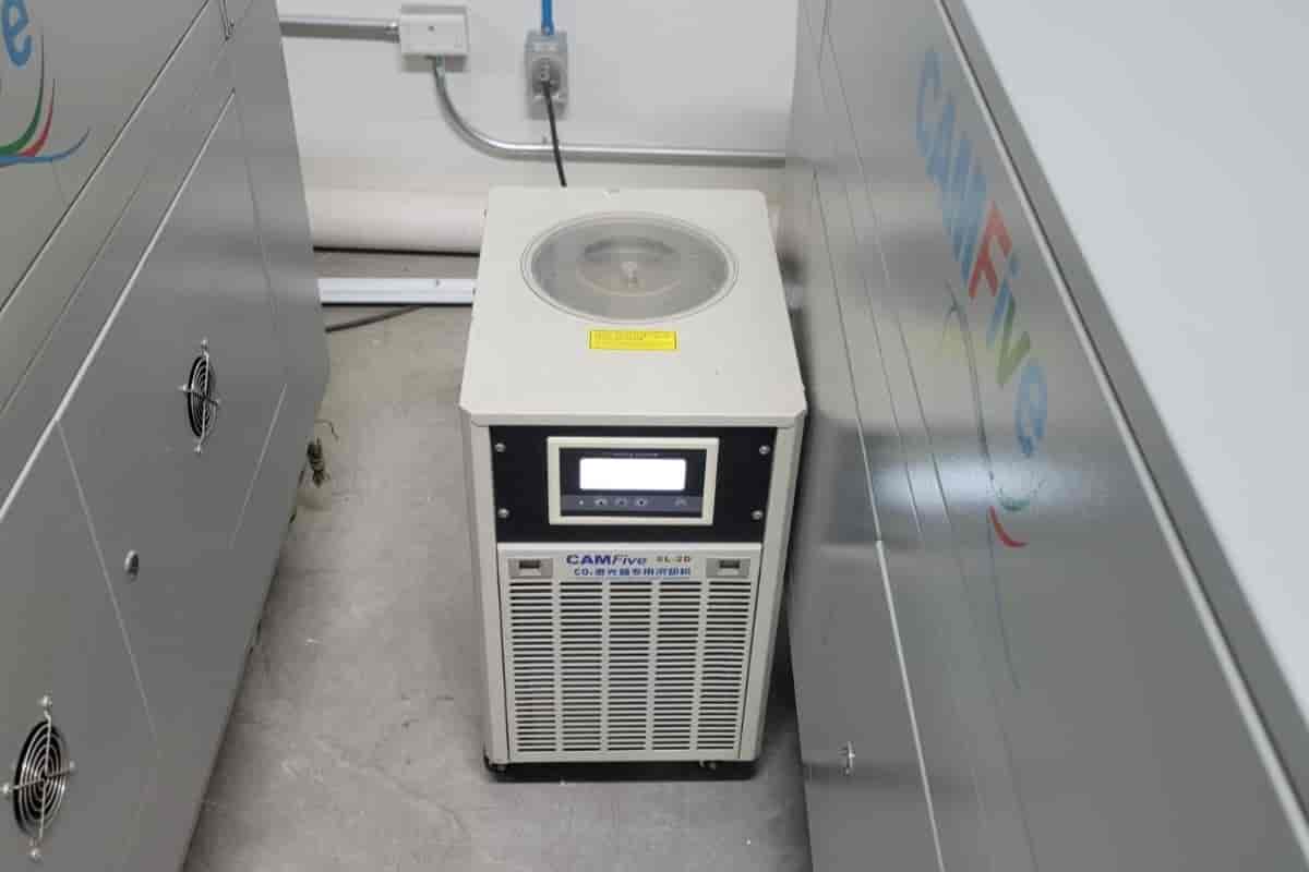
Ventilation
To begin working with the cutter, the very first step is to turn on the ventilation system, we do this by turning on the multi-contact at the back of the machine. Once on, we have to check the ventilation system for any obstructions and ensure that the water tank is full.
-
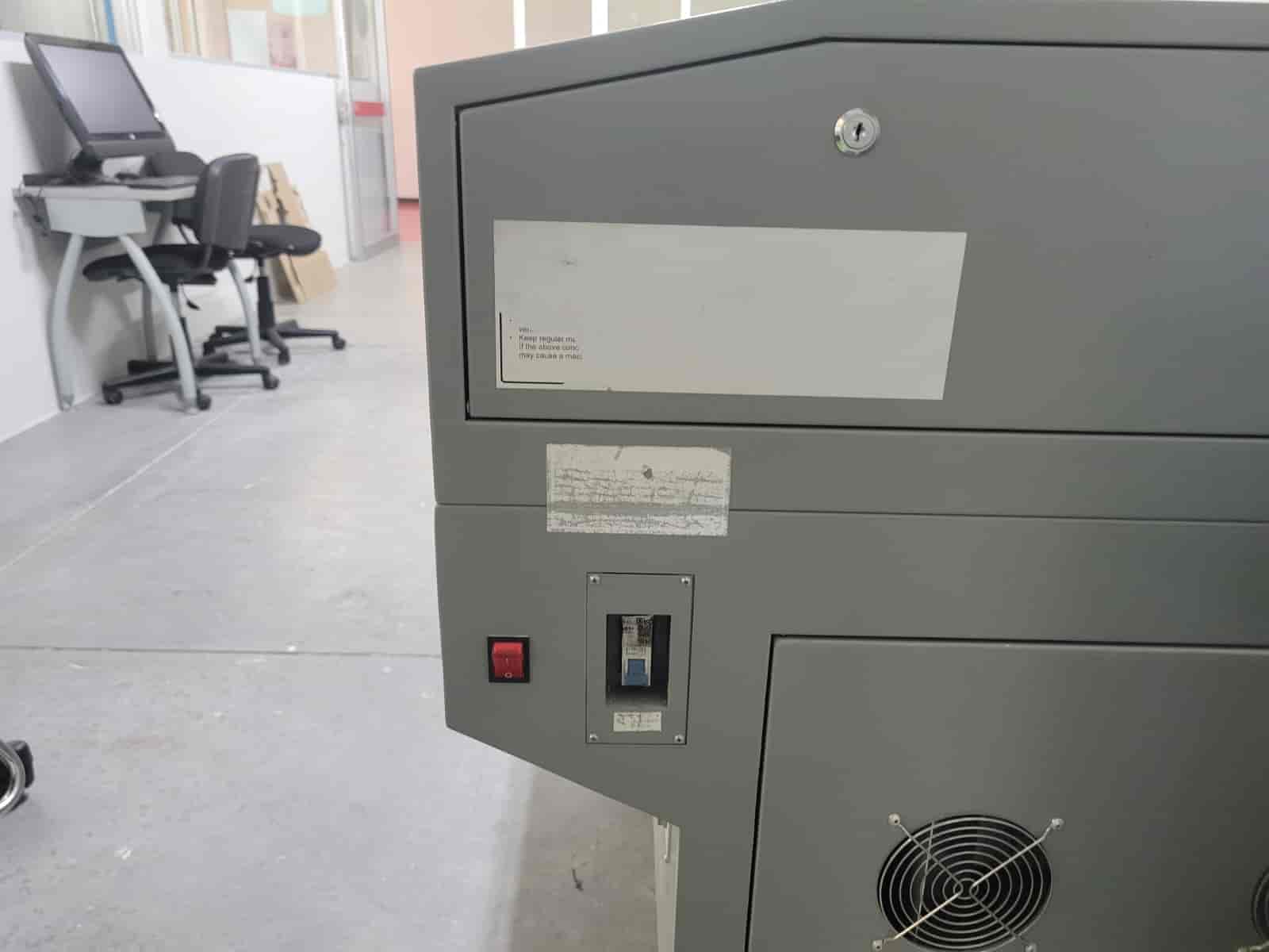
Power
At the left side of the machine, we will see a blue switch on it's off position, we will flip the switch to give power to the machine's main systems.
-
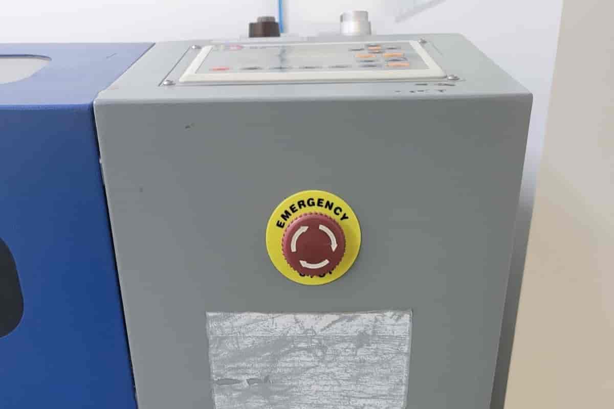
Disengage the Safety Stop System
At the front right of the machine we can find the emergency stop button, which is always engaged when the machine is not in use. To disengage the emergency stop we have to rotate the button in a clockwise direction until it pops out.
-
Key
The final step is to insert and turn the key into the keyhole on the top right of the machine, just behind the console. With this, the machine is fully operational and ready for the cutting process.
7. Laser Cutting Process
Once the activation is complete and the machine is in its fully operational state, we have to follow these steps to begin our cutting process:
-
USB Insertion
On the front right of the machine we will find an USB port, here we have to insert our USB with our .oud files. Make sure that the USB is in good conditions, a problem that I ran into was that the machine was incapable of reading my files because of a damaged USB.
-
Copy Files to Ram
In the machine console, we will press the file button, when the file menu opens, we will position ourselves on the Open Udisk option using the arrow buttons, and press enter.
If we saved our files correctly, they will appear on the left side of the screen, after which we will choose the correct file and select the Copy to Ram option, this will save the file into the machine.
Once done with the file menu,we push the escape button until we are back at the main menu.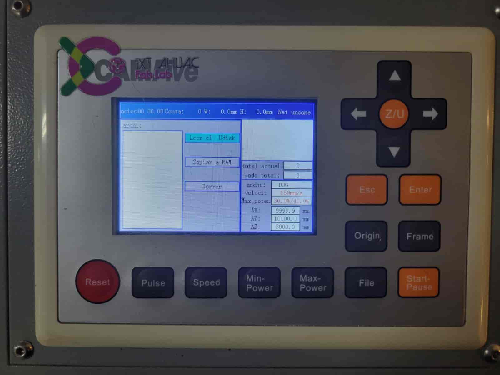
-
Load the material
To load the material, in my case a 1.5 by 1 meters, 2.5 mm thick MDF sheet, we first have to clear the working area of the laser head, we can control the laser head's position through the arrow buttons. This can be done from either the main menu or after choosing our file.
We press the up arrow until the laser head is located far enough to the back, where we can be sure that we won't hit it while loading our material. We also check the work area for any debris that could alter our material's elevation.
Once the work area is clear, we simply place the material inside, we can aid ourselves with the work area's borders to keep our material in an optimal position.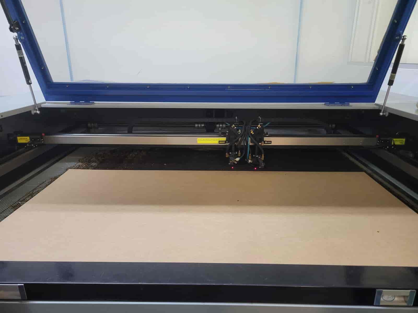
-
Laser head adjustments
To ensure a precise cut with minimal kerf, we have to adjust the laser head's elevation in relation to our material, with the optimal distance between them being 5 mm. We have to be extremely careful during this step to avoid causing any damage to the laser head.
First, we bring the laser head on top of a border of our material where we can easily observe and manipulate the laser head, we proceed to check the distance between the laser head and the material, we can do this with any 5 mm tall object, which, coincidentaly, is the approximate height of a USB connector, so you can use the same USB that you used to upload your files.
If the distance is too close or too far, we can adjust it by loosening the large screw on the laser head and moving the head up or down. Be very careful, have a stable grip on the head to avoid letting it fall down, and make sure you don't disconnect any components.
Once in the correct position, re-tighten the screw.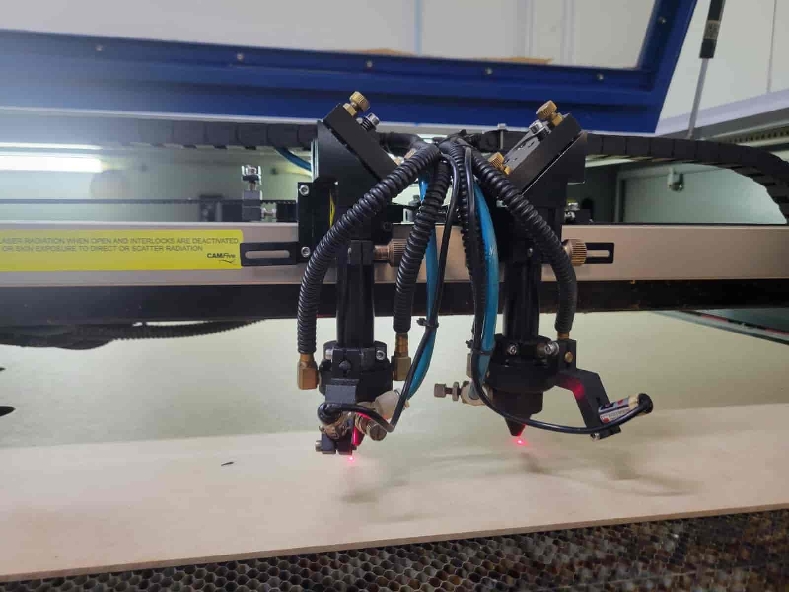
-
Preparing our file
We open the file menu and we choose our file, after which we can move the laser head to the point we want to use as origin, we first press the frame button, which will show us the maximum rectangular area of our project.
If we are satisfied with the frame preview, we press origin, which will set that point as the origin of the cutting process, and it will be the same point in the design that we configured in SmartCarve.
We can check if the origin is correctly defined by moving the laser head to any point and pressing escape, at which point the laser head should return to the established origin.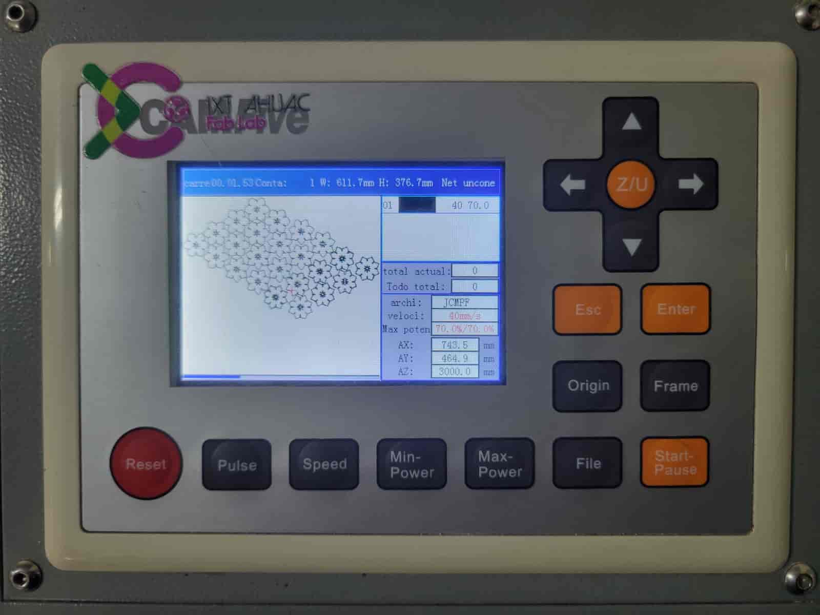
-
Laser activation
The final step before the cutting begins is to activate the laser. Since the laser is invisible to the human eye and it is exposed over the laser head axis, we have to close the machine's door as a safety measure to avoid making accidental contact with the laser.
Once the door is closed, we proceed to turn the chosen laser's potentiometer clockwise to the maximum or both laser's potentiometers if we want to cut the same design twice at the same time, when using both lasers, properly adjust your designs dimensions and the distance between the laser heads, which you can manually change.
I will be using the right laser head only, so I turn the right potentiometer into its maximum position. When the laser's power level is to the max, we press the laser activation button next to the key port, this will turn on the laser.
Remember; once the laser is on, do not open the door.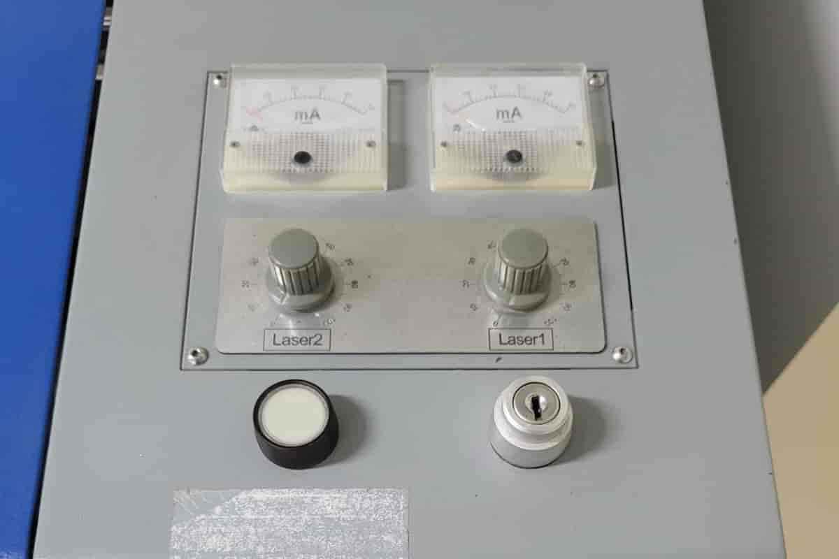
-
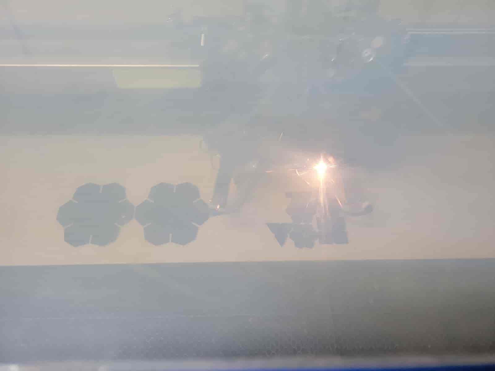
Cutting
We do a final check, file, origin, frame and laser output. We can now press the start button, and the cutting will begin immediately, now we just have to supervise the machine until the process is complete, we should be ready to hit the safety stop at any time if we observe any anomalies and especially fires.
8. Deactivation and Final Procedures
When our cut is finished, we have to follow these steps to turn off the machine:
-
Turning off the laser
We push the laser power button to turn it off and return the laser's potentiometer to its zero position.
-
Material extraction
We move the laser head to the back so we can remove the sheet without the risk of an accidental colition with the lenses, we open the door and remove the sheet.
We remove our final product and any scraps that might remain on the work area. -
Machine deactivation
We deactivate the machine by repeating the activation sequence, but now in reverse, starting with removing the key, then engaging the safety stop, turning off the power switch and finally, turning off the ventilation system.
-
Final considerations
Remove any leftover materials from the premises, don't forget your USB in the machine's port and return both the software licence key and machine key to your instructor.
-
Checkout registration
Register the time you finished working in the Fab Lab's log.
9. Testing my design
For the first test, I cut two Universal Pieces with a slot joint width of 2.35 mm, the design parameter set as <"Width" - "Kerf">. I followed all of the previoulsy mentioned steps succesfully, but, as I figured out after the cutting process, the joints were too loose and didn't have enough depth.
I increased the depth of the joints and made minor changes to the length of the sides, after which I did my second cut. The depth correction helped tighten the joints, but it wasn't even close to being a press fit.
After discussing these results with a senior classmate, I decided to change the joint width to 2.30 mm, updating the parameter to <"Width" - "Kerf" - 0.05>.
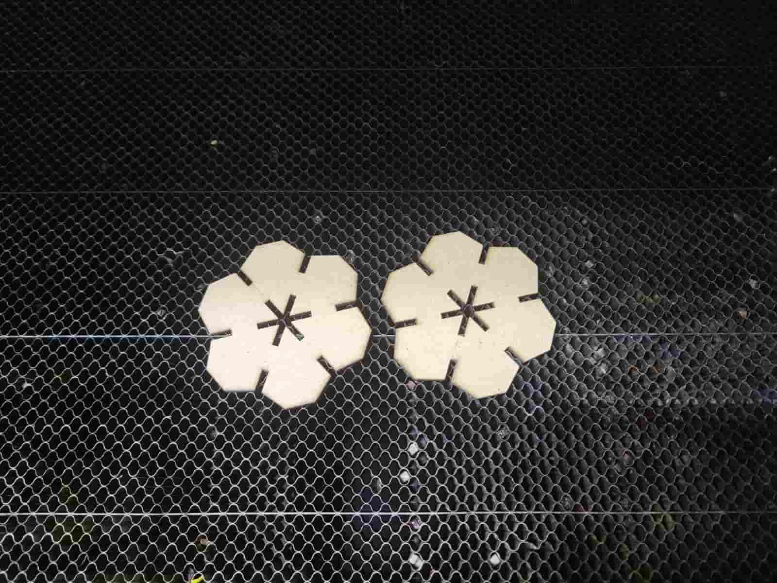
I conducted the third test, cutting two of the updated Universal Pieces. The modifications proved to be effective. And I began to design the new parts based on the correct parameters.
10. Part Variant Design
As stated in section 3.4, one of the intended features of the Universal Piece design was to be able to create different shapes by changing the parameter that controls the number of sides.
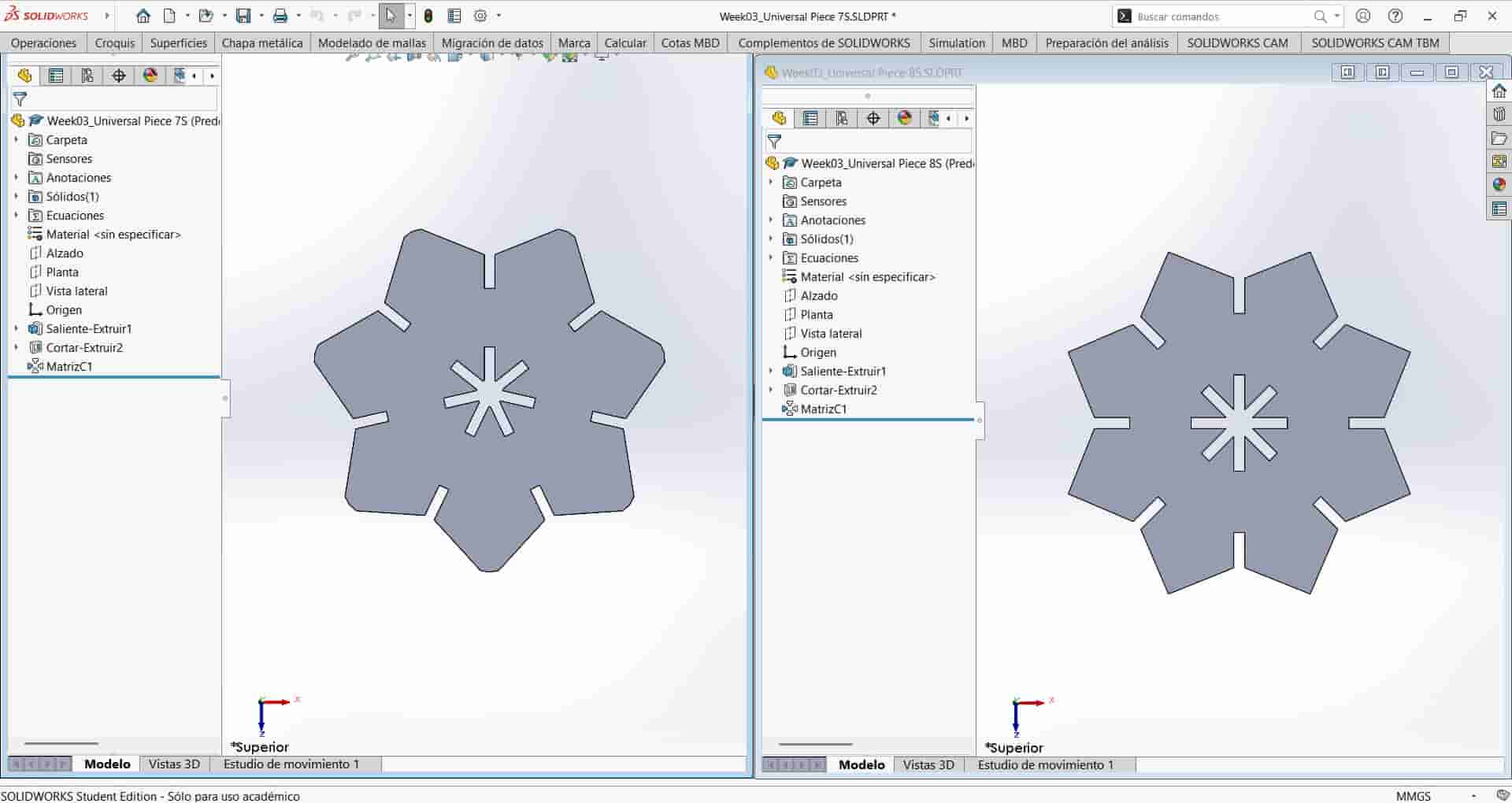
I create two copies of the Universal Piece part document, and I name them Universal Piece 7S and Universal Piece 8S. I then open each file and modify the <N_Sides> parameter to 7 and 8 for each respective part.
These are the results:
11. Final Cutting Pattern
I created a new assembly and inserted the same part parameters for reference, while adding a new parameter <"N_Parts" = 8>. This parameter will control the ammount of each part.
I inserted the original, six sided Universal Piece and created a linear component pattern, setting the edges of two consecutive slot joints as the directions. Based on the parameters, I input <"Diameter" * 0.92> for the distance between instances and <"N_Parts"/2> and 2 for the number of instances in the first and second direction, respectively. These values weren't calculated with too much thought, they just had to account for 8 total instances and enough distance between them to ensure precise cuts, while minimizing wasted material.
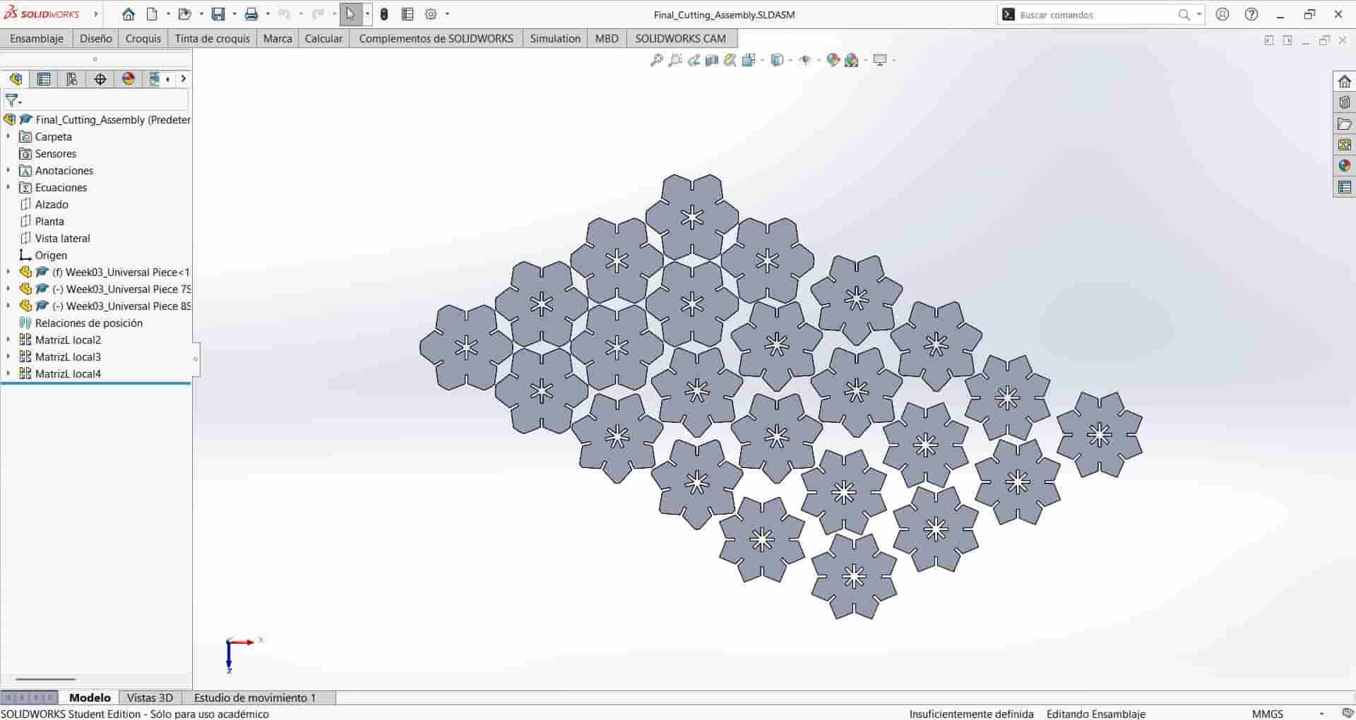
I then insert the second and third parts and repeat the linear pattern with each one, again, without any special consideration for the values, you just have to focus on keeping the pieces close enough together, but with enough distance between them for the laser to cut each part accurately without carving into another.
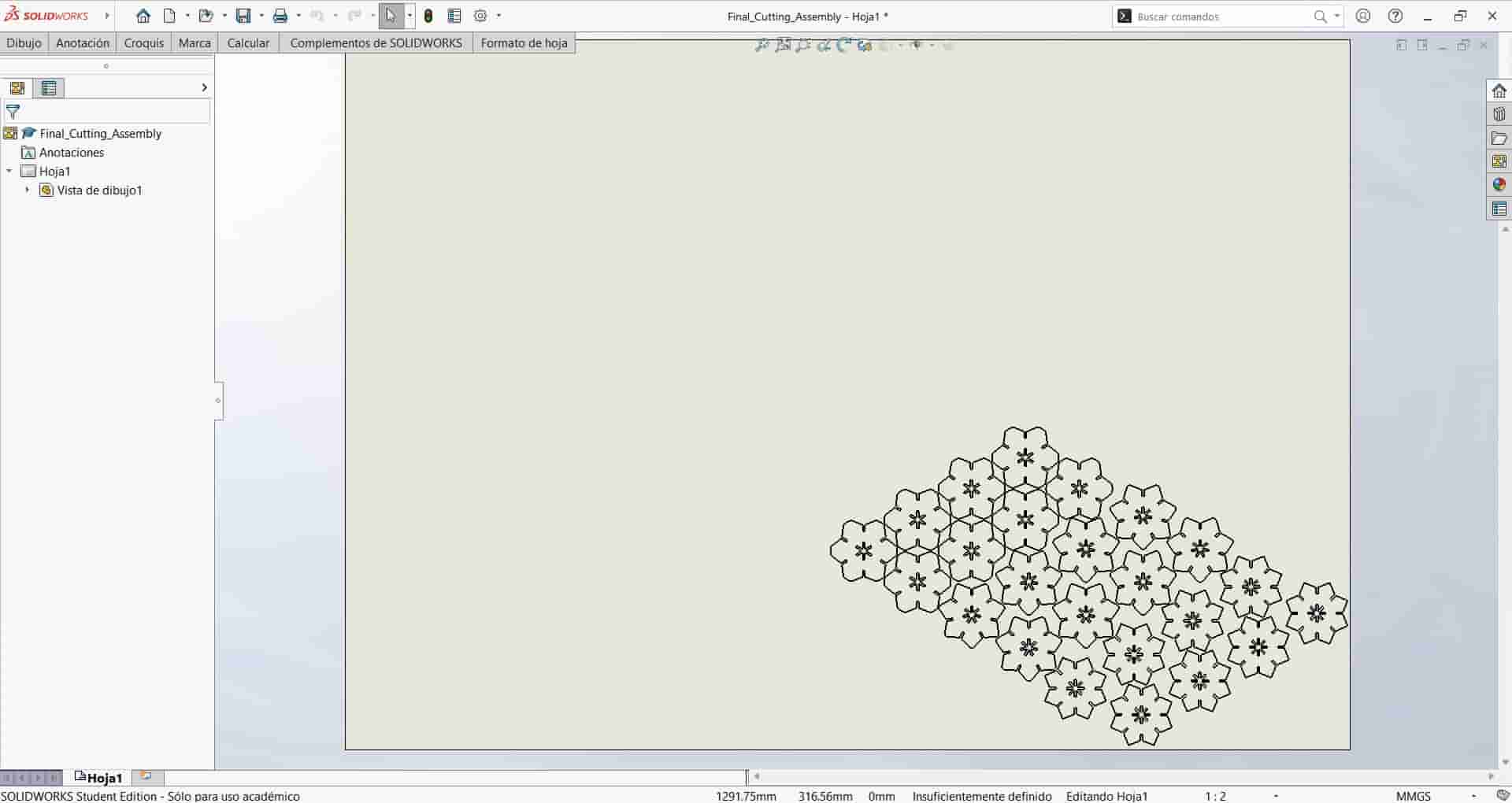
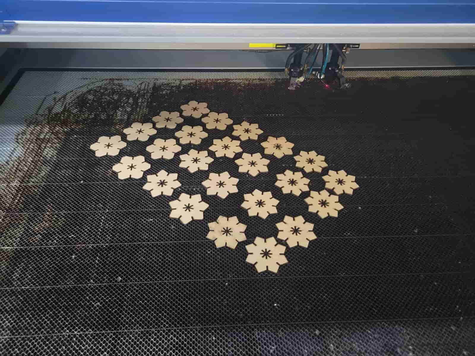
I created a new A0 sized drawing, imported the view of the assembly, deleted the sheet format and exported the .dxf file.
We proceed to import the .dxf file to SmartCarve, apply the same power and speed parameters, and export our .oud file.
We boot up the laser cutter and get to cutting.
Here are the final cutouts::
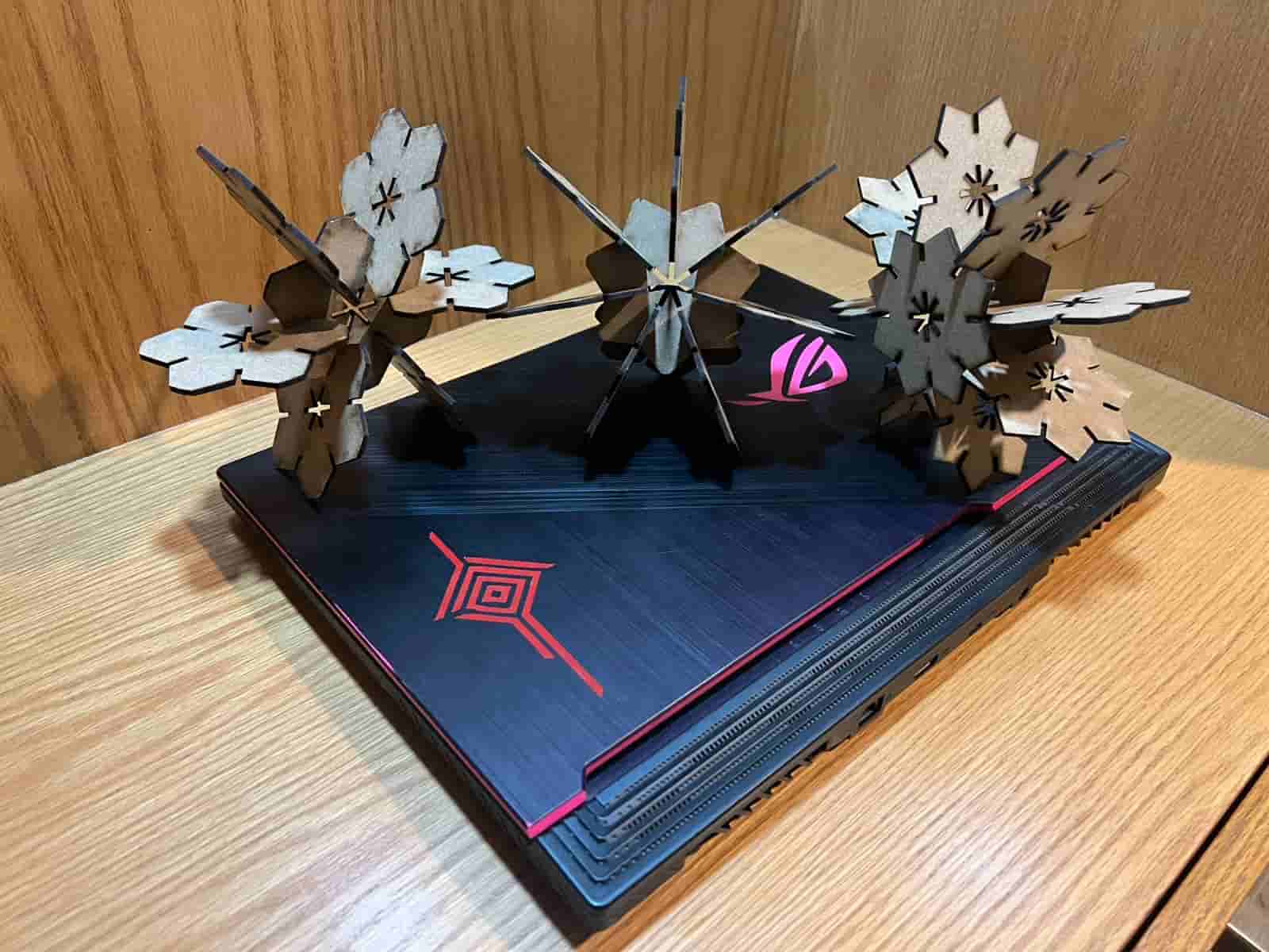
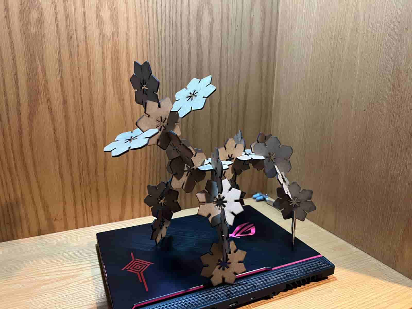
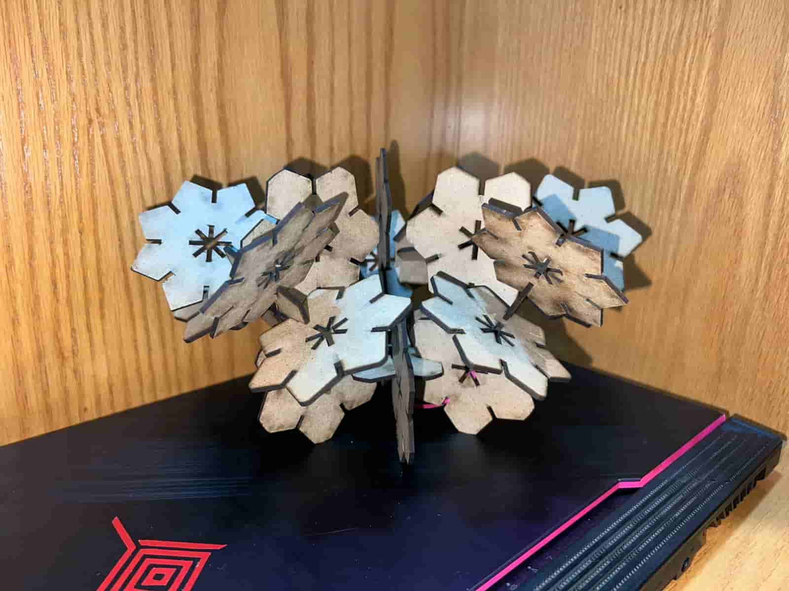
12. Parametric Construcion Kit Results
I was very satisfied with the results of the kit, they fit nicely together and can be configured in a great variety of shapes.
Here are my hero shots:
13. Vinyl Cutting
Vinyl cutting is a computer controlled cutting process that involves turning a vector based design into instructions for a vinyl cutter, for the purpose of cutting thin, adhesive vinyl sheets. The machine reads the vectorized design and moves a small blade to precisely cut the shapes into the sheet.
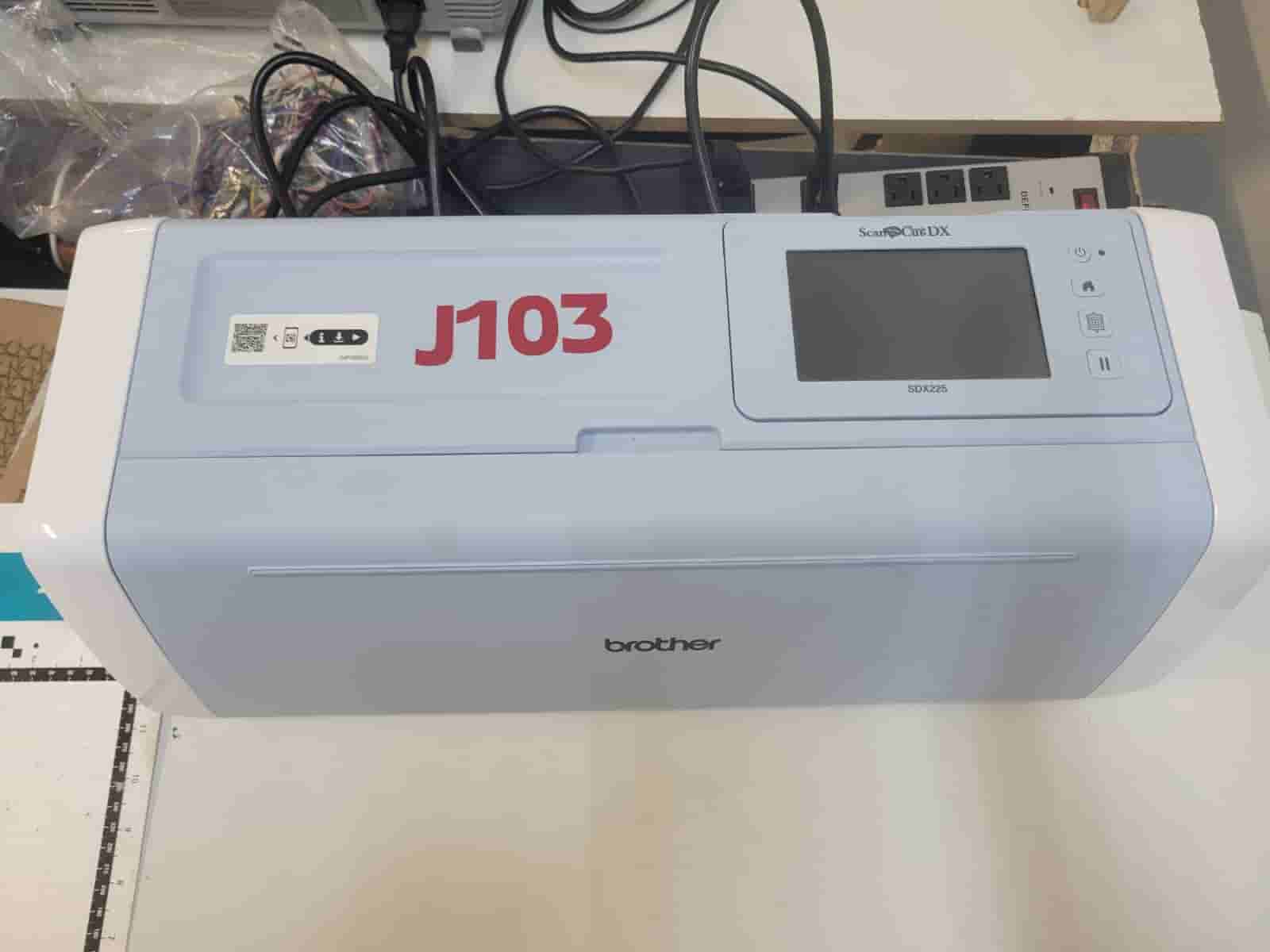
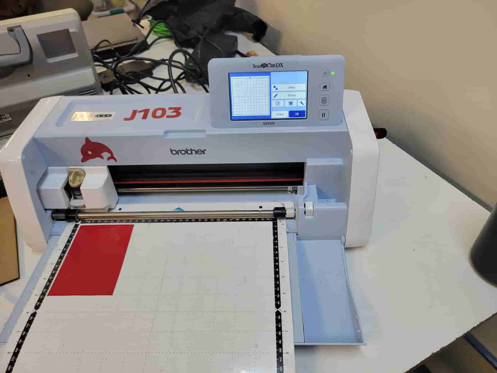
The machine that we will be using is a Brother J103 vinyl cutter.
14. Design
The final design must be a .svg file or other vector based file, for which Inkscape is an appropiate software in skilled hands. Yet, I decided to begin in SolidWorks due to my greater familiarity and skill with the software.
I create a new part document and begin a new sketch, starting with a simple rhombus which I proceed to offset three times. I then draw the remaining lines one by one, establishing geometrical relations such as parallelism and perpendicularity to maintain a consistent geometry.
I create the four parameters in the equations manager and begin dimensioning the sketch. As you can see, most dimensions are equal, so there wasn't a need for complex parameters or equations.
 I extruded the sketch and took a screenshot of the solid, this is the picture that we will import into Inkscape.

15. Vectorization
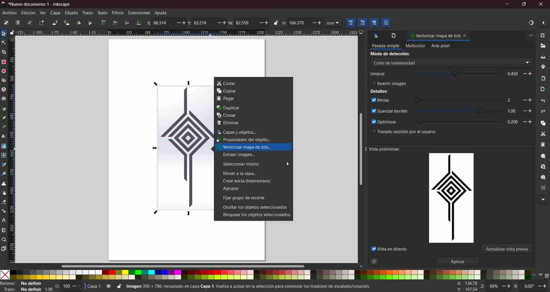
We start a new Inkscape document and import the screenshot of the design.
We then center the picture and right click on top of it. Among the displayed options, we will click on the one named vectorize bit map, and click apply at the bottom of the menu on the right.
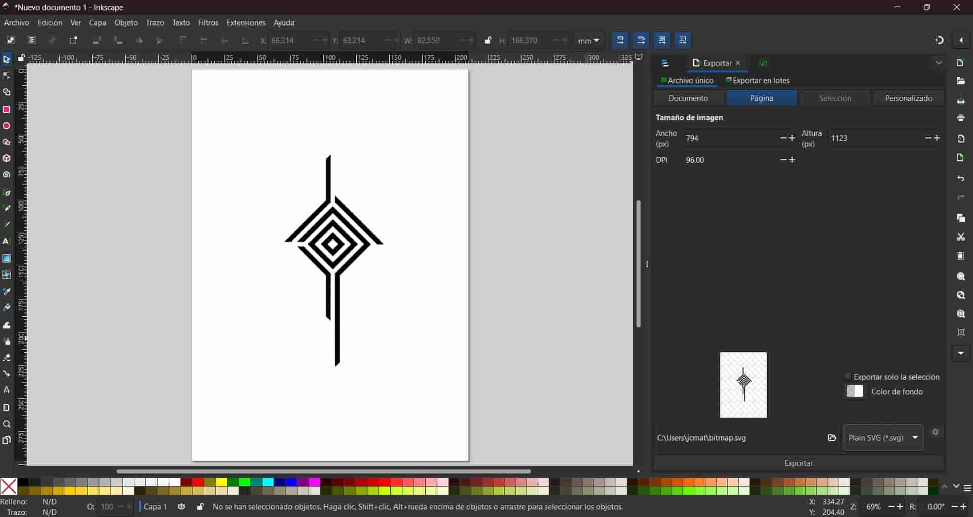
We delete the screenshot from the canvas, leaving only the vectorized image.
Finally, we export the document as a .svg file and copy it into our USB drive.
16. Using the Vinyl Cutter
Compared to the laser cutter, the vinyl cutter is a way simpler machine, we have to follow the next steps to cut our design:
Turn on the machine
Connect the machine to a power outlet, open the tray and control panel, and press the power button, this will turn on the machine.
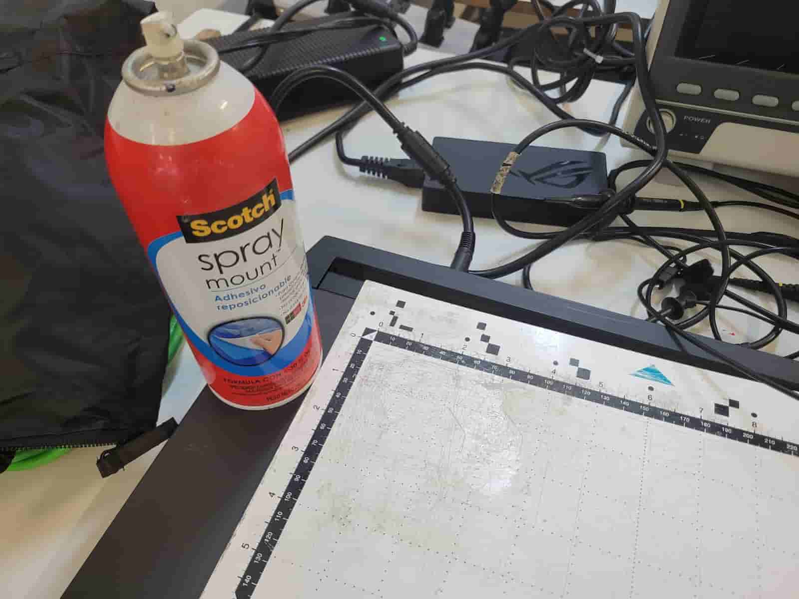
Press the home button.Cut and paste vinyl into carpet
Cut a piece of vinyl and spray a small ammount of lacquer on the top side of the carpet, which is the side with the black edges, then, paste the piece of vinyl on the carpet, avoid pasting the material over the black edges.
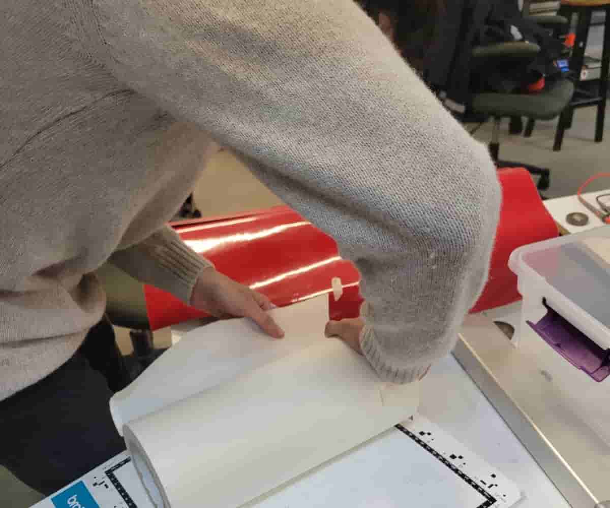
Load the carpet
Place the carpet bellow the cylinder, with the arrow facing the machine and following the guides along the sides, do not force the carpet in. Press the button bellow the home button to load the carpet.
Selecting our file
Insert your USB into the port on the right side of the machine
In the home menu, use the touch screen to select the retrieve data option.
Select the USB option and choose your .svg file.Edit the file
Edit your object's size and position to make it fit within the size of your piece of vinyl. You can use the grid on the screen and on the carpet as reference.
When you are finished, press the OK button.
Set up cut parameters
Select the cut option and press on the wrench button, proceed to input the pressure and speed parameters, in my case I inputed 3 pressure and 2 speed.
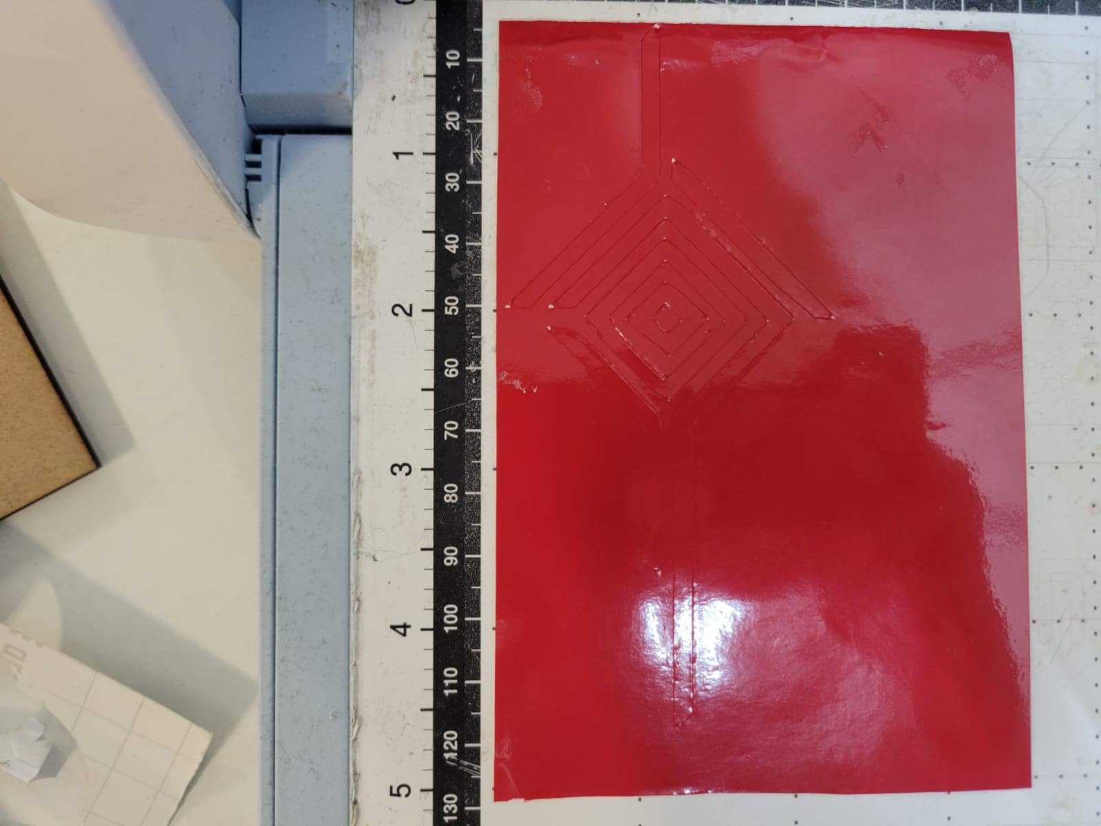
Start the cutting process
Press the star button and wait for the machine to finish. Our machine experiences a bit of wobbliness on the tool head, so I gently support it with my hand during the cutting process.
Extract the carpet
When the cutting is finished, press the button bellow the home button to extract the carpet.
17. Vinyl Cutout Extraction
To extract our cutout from the carpet, we have to follow the next steps:
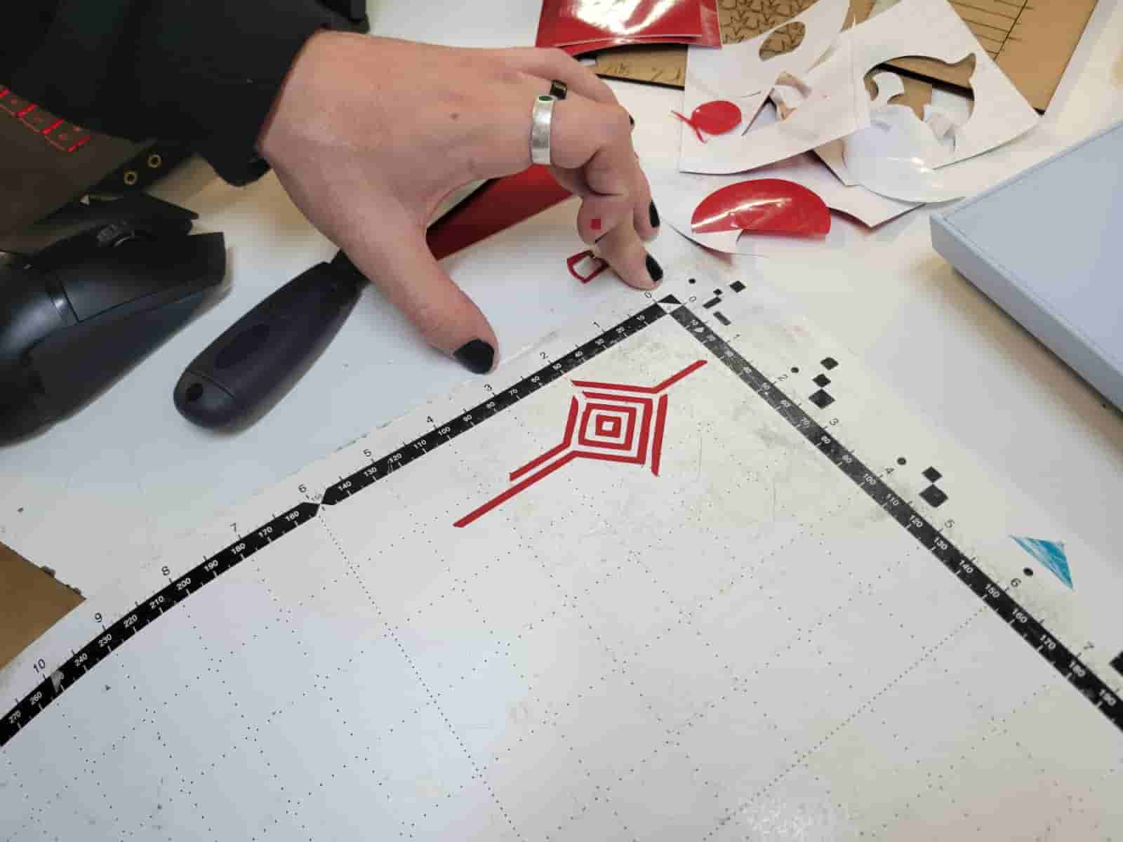
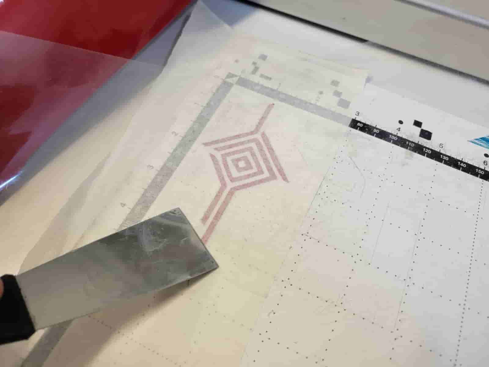
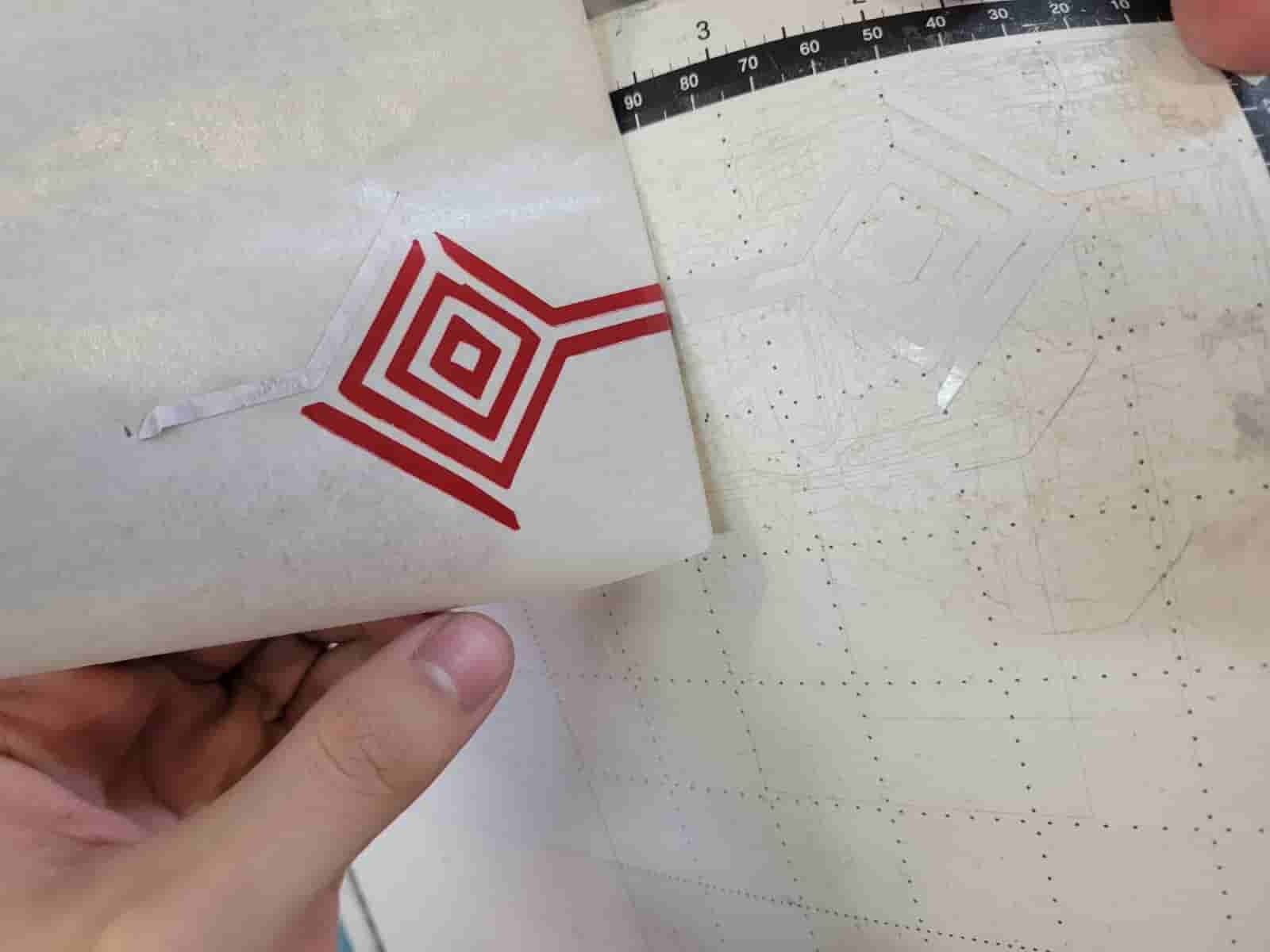
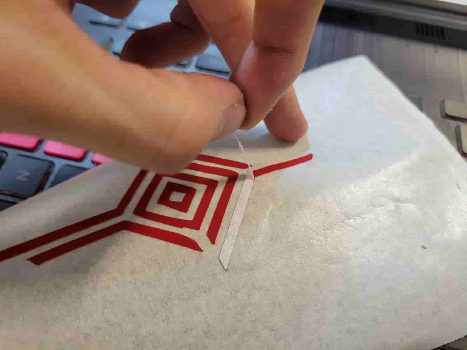
Remove waste material
Use a box cutter or small tweezers to remove the waste material from the carpet, leaving only the desired cutout.
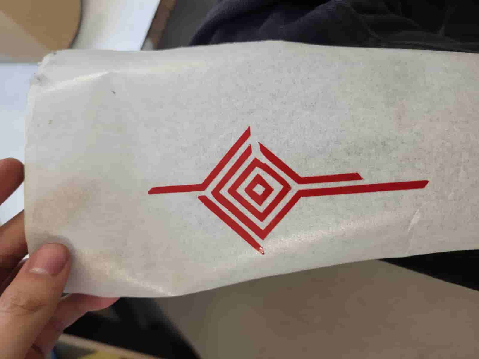
Place Vinyl Transfer Tape
Paste a piece of vinyl transfer tape on top of the cutout. Apply pressure on top of the cutout.
Remove cutout
Start lifting the transfer tape at a slow pace, if any parts of the cutout don't stick, apply more pressure on the cutout and try again.
Peel off backing paper
If any pieces of backing paper remained on the cutout after removing it from the carpet, peel them off with a box cutter or tweezers.
Paste the cutout
Paste the cutout in the surface of your choice, apply lots of pressure.
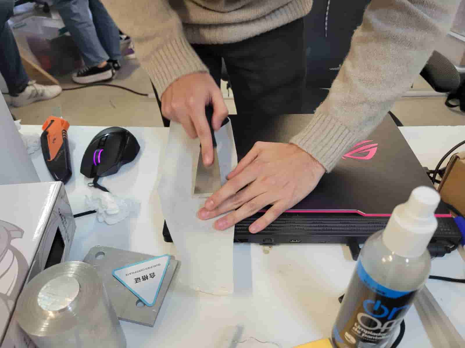
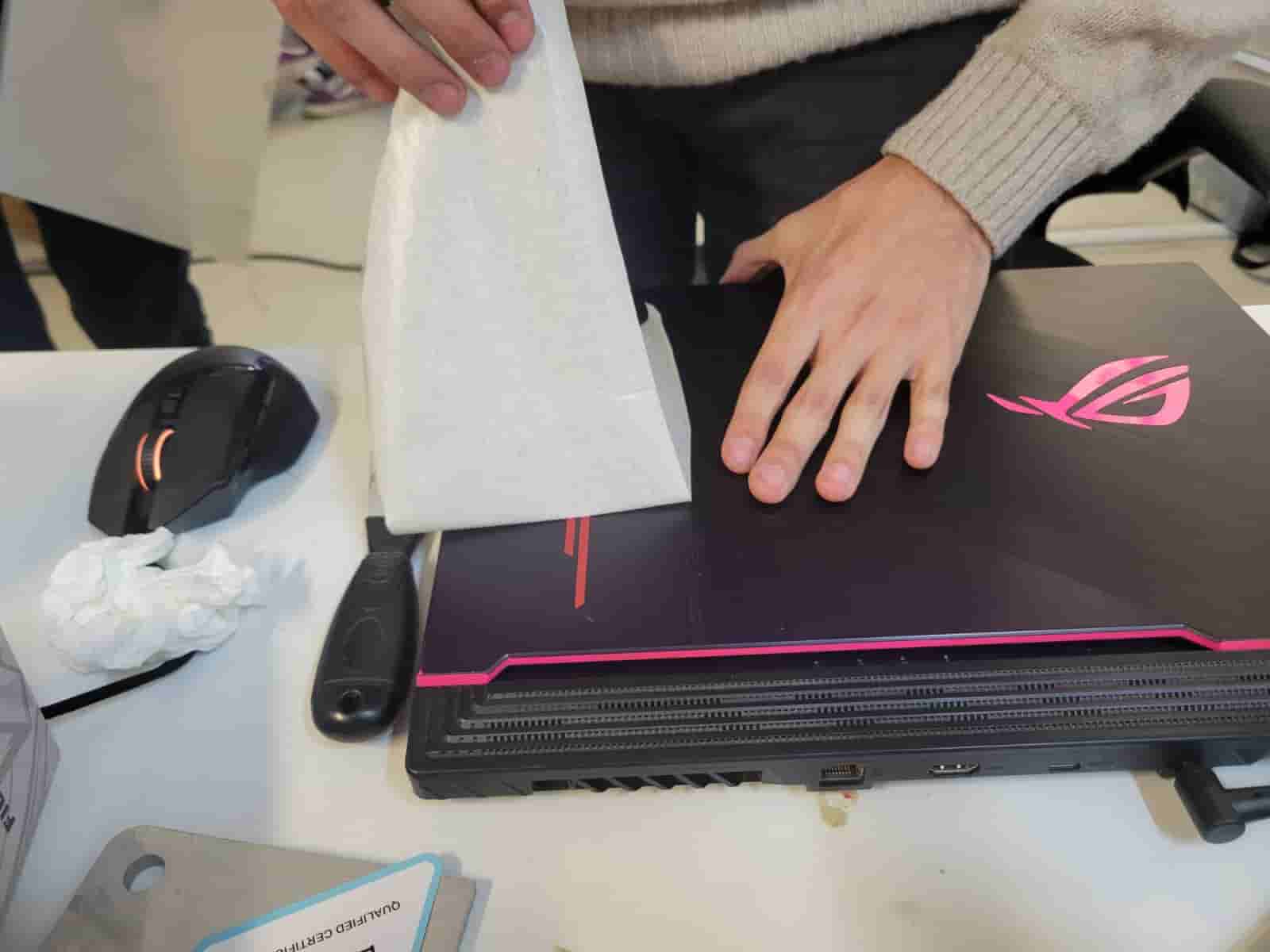
Remove transfer tape
Remove the transfer tape slowly, if the cutout is still sticking to it, then lower it into the surface and apply additional pressure.
Clean the carpet
Clean the carpet with ethanol until the lacquer comes off.
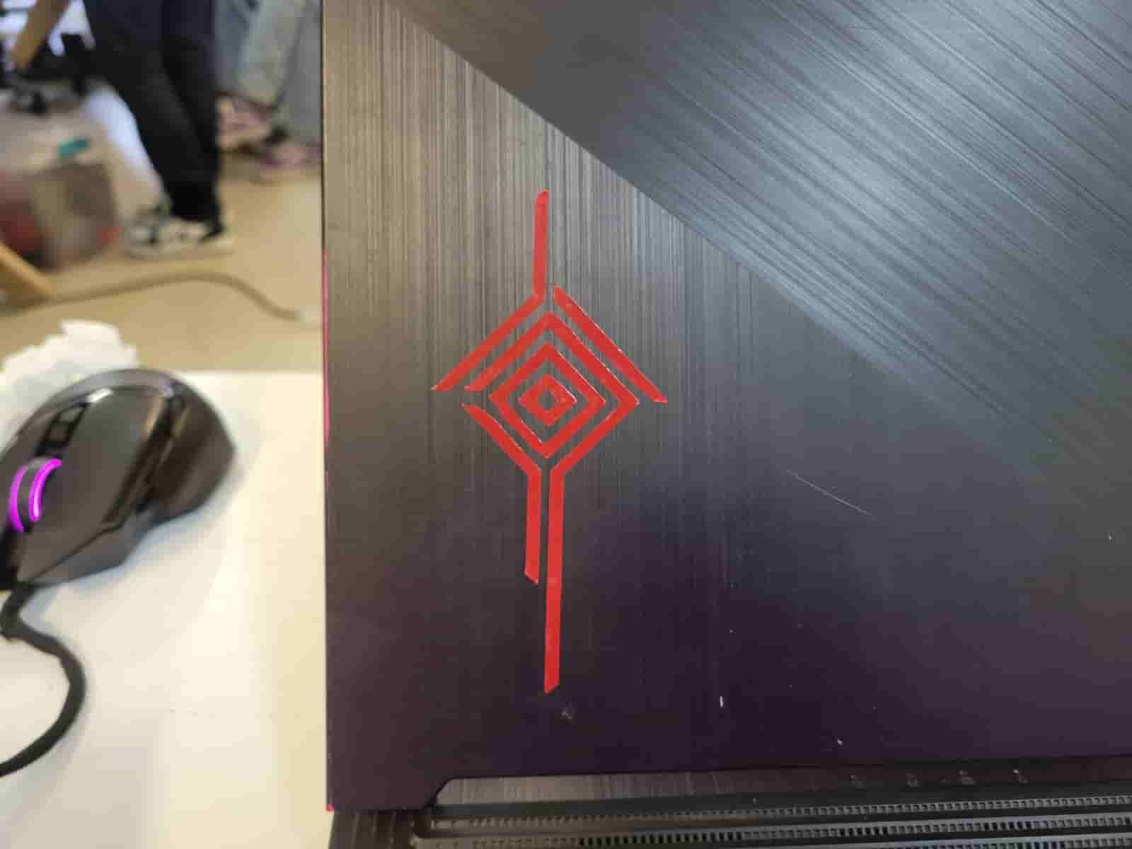
18. Vinyl Cutout Results
Here are the final results, which I was very satisfied with;
19. Comments and Recommendations
I want to thank my peer Apolinar Velazquez for helping understand the operation of the laser cutter, his inputs were very valluable for my learning experience.
Working with machines like the laser cutter can be intimidating, especially for people with little to no experience, ask your more experienced classmates and instructors for help.
As I explained in section 9, we will sometimes need to conduct multiple tests, so take that time into consideration.
20. Learning Outcomes
I learned how to create and use parameters for my designs. I learned how to operate a laser cutter and a vinyl cutter. I succesfully designed and produced a laser cut parametric construction kit and a vinyl cutout.