Week 3
Computer Aided Cutting
Fab Academy 2024
Riichiro Yamamoto
- Group Assignment
- Vinyl Cut Test
- Press Fit Kit
- Living Hinge Test
- Double Curvature Surface/ins>
- Origami
Group Assignment
As a group assignment for this week, we had to experiment with cutting material with a laser cutting machine and understand how to work with the machine. It was the first time we worked as a whole class. Personally, it was a precious time exchanging opinions with each other.
Here is the link to the group assignment page
.jpg)
Vinyl Cut Test
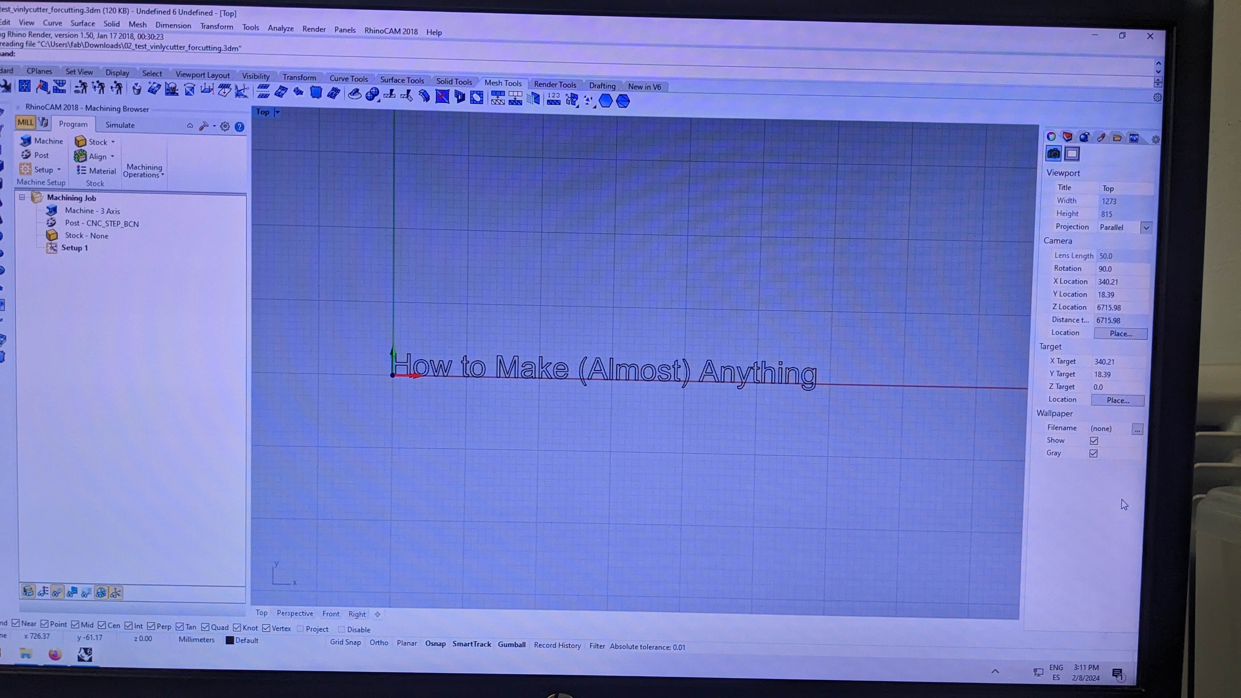
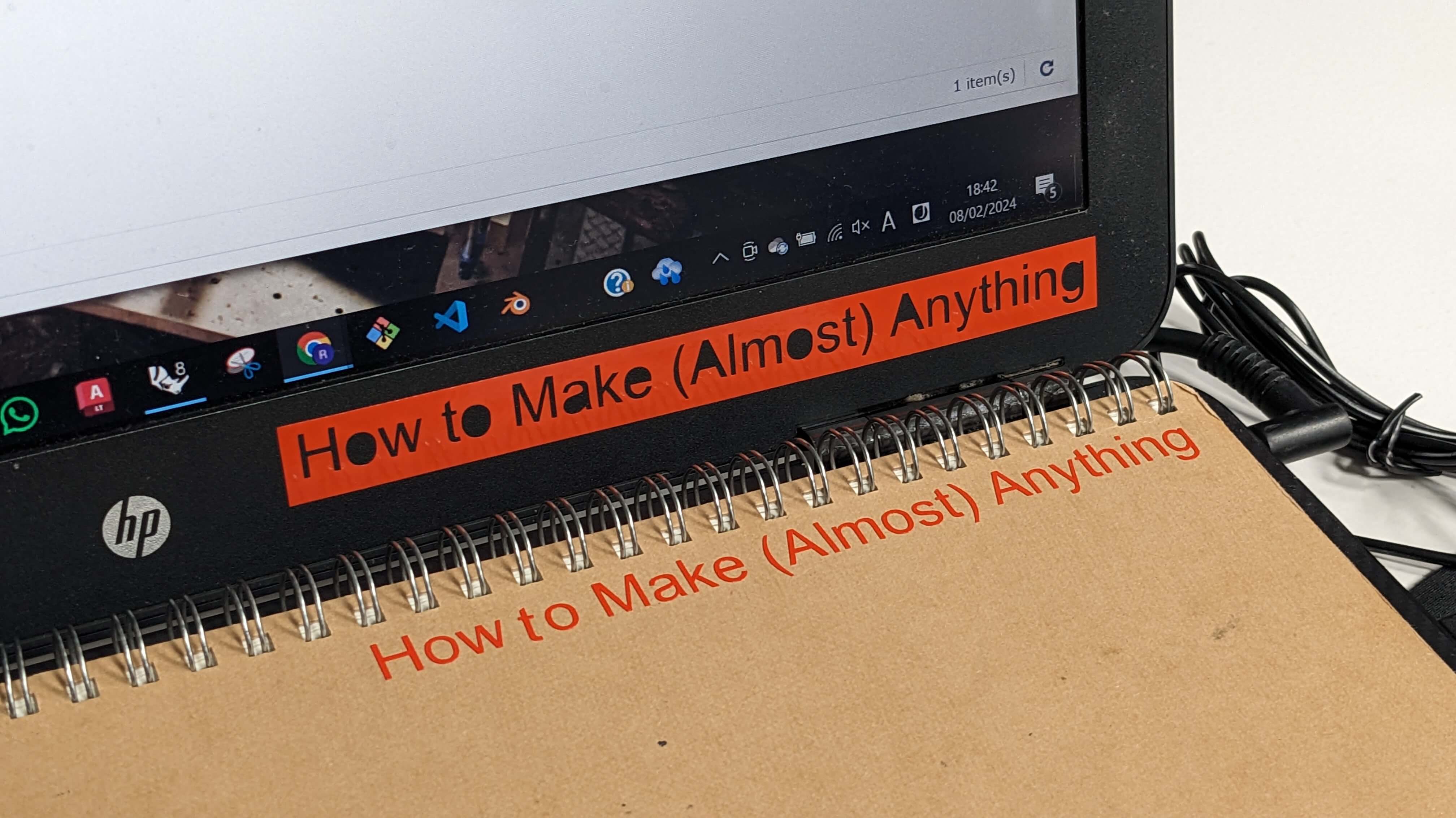
For the first time working with a vinyl cutter, I wanted to try cutting simple shapes quickly. So I decided to cut out the famous and beautiful sentence “How to Make (Almost) Anything.
First, I modelled the sentence as vector data in Rhino and made sure the vector lines were joined together. Then, I saved the file in Rhino 5 format and transferred the file through IAAC Cloud to another computer that was already connected to the vinyl cutter.
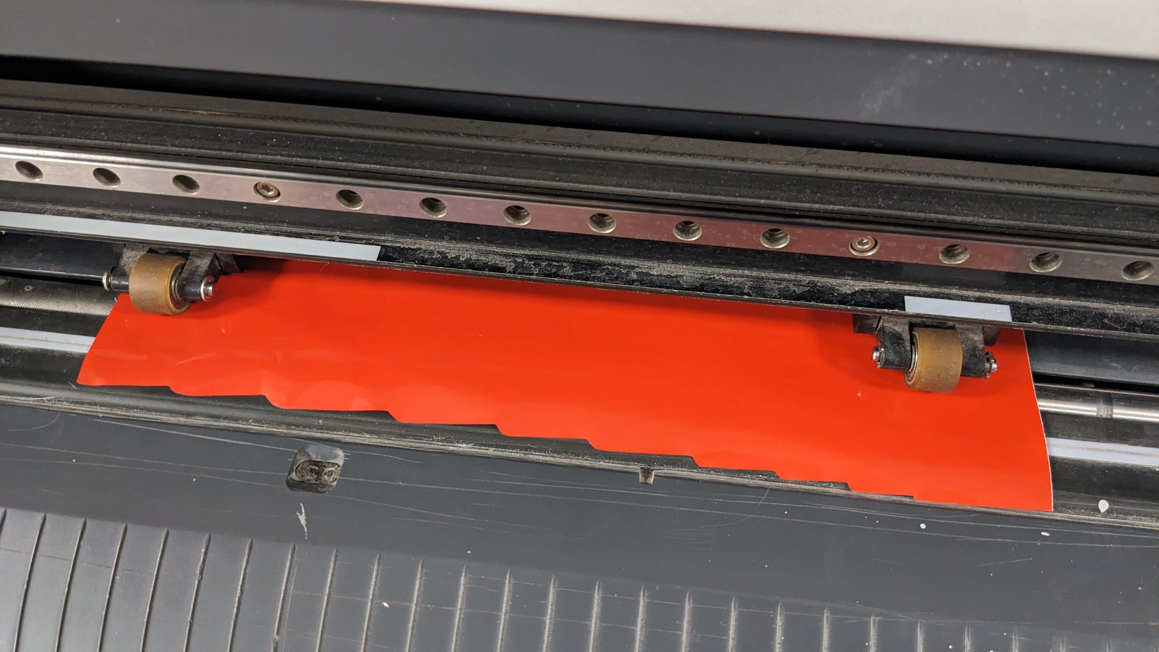
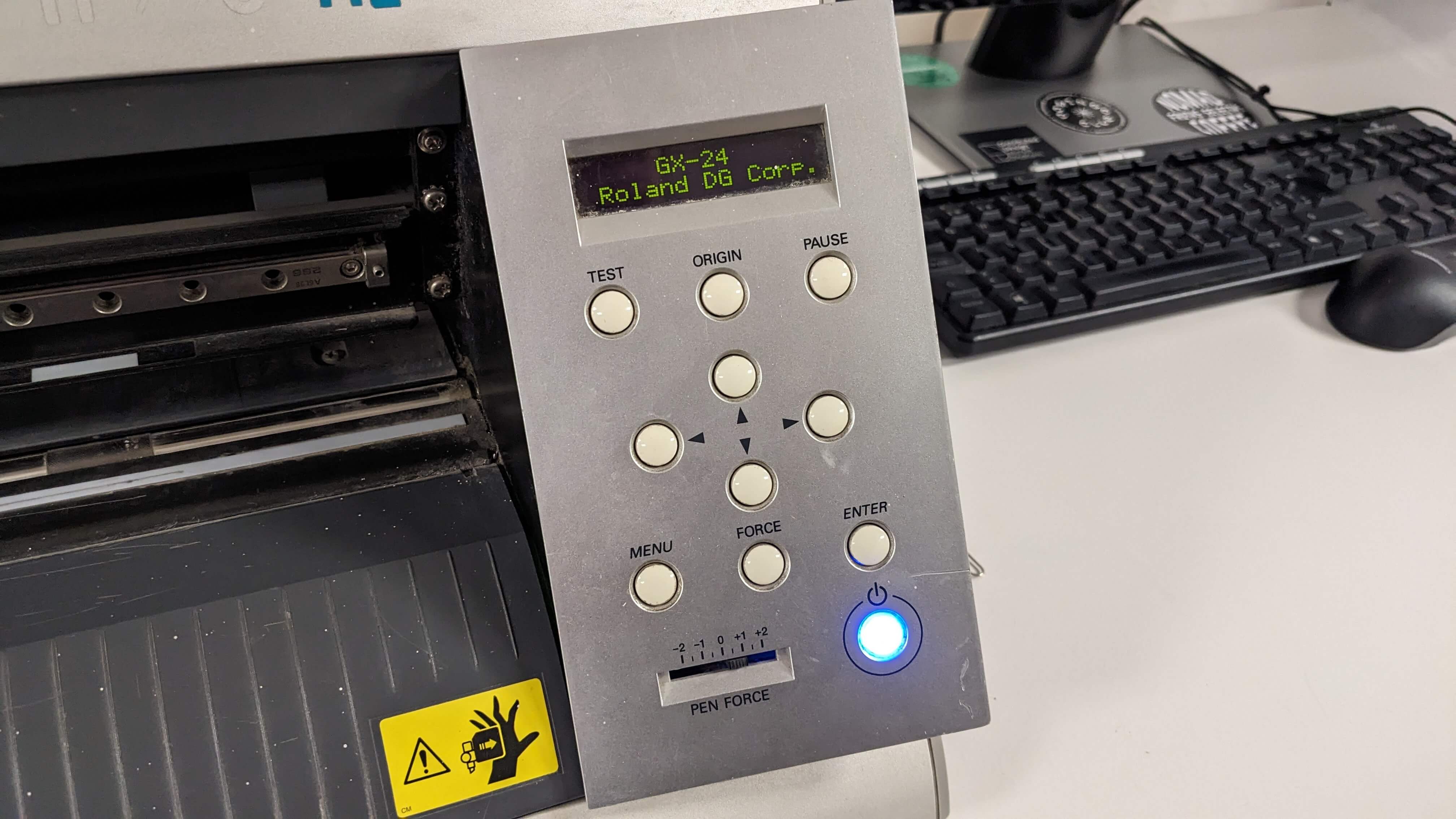
The vinyl cutter I used was a Roland CAMM-1 GX-24. I will explain below the process of working with the vinyl cutter in step by step.
- Unlock the roller by pushing down a handle
- Insert a sheet of material from the back of the machine
- Adjust the roller position in areas highlighted in white
- Make sure the material is set beyond the white line
- Set the roller by pulling up the handle
- Turn on the vinyl cutter
- Select the type of material either Roll or Piece
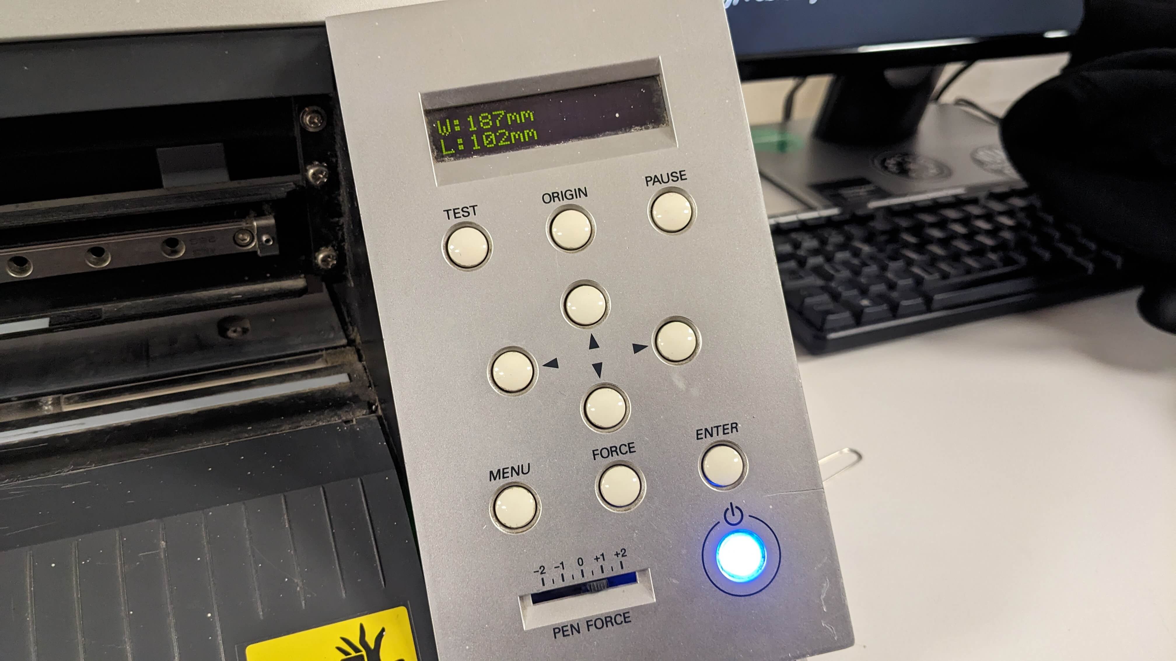
- Press Enter, and then the machine will automatically measure the dimensions of the material
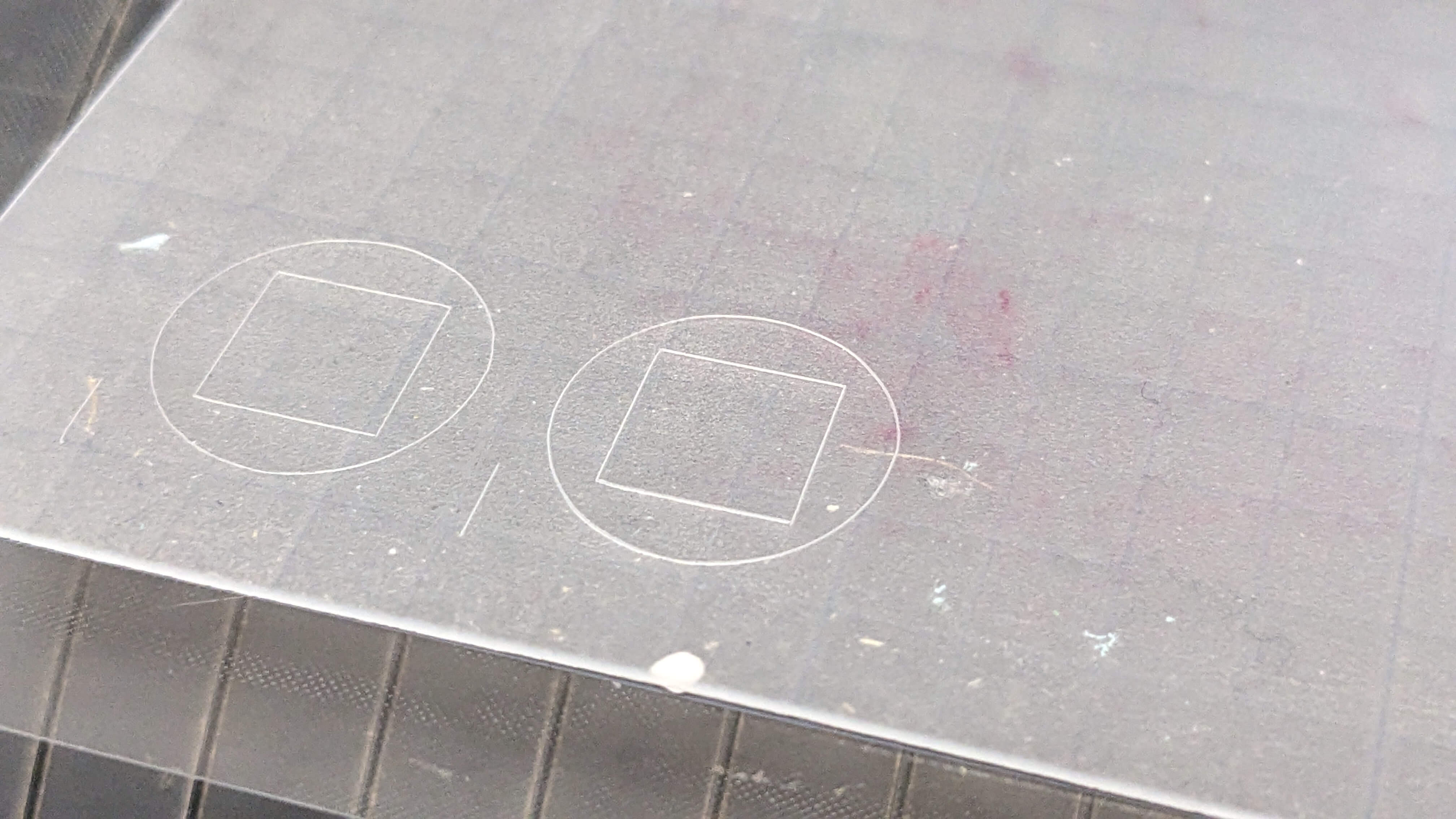
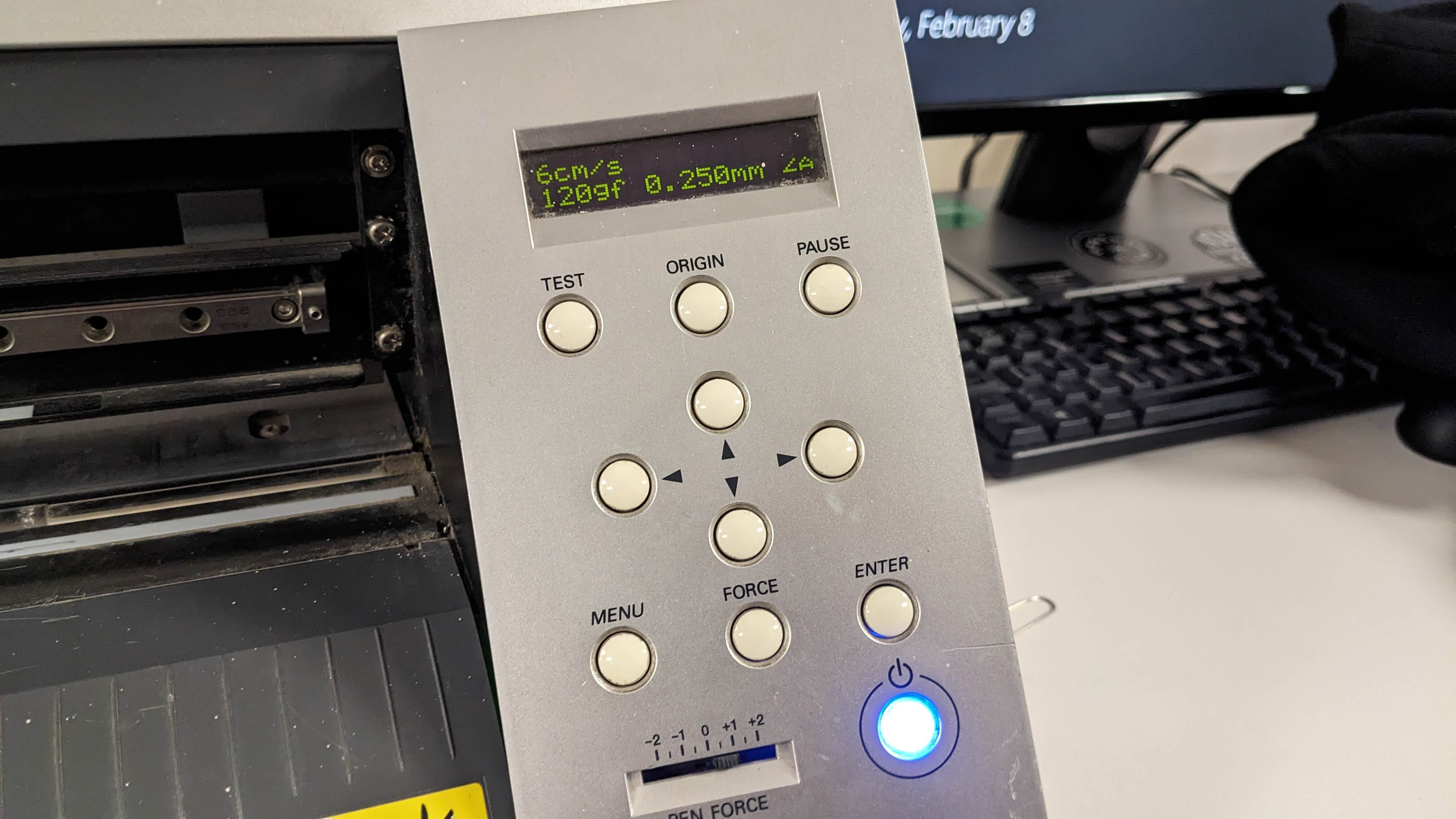
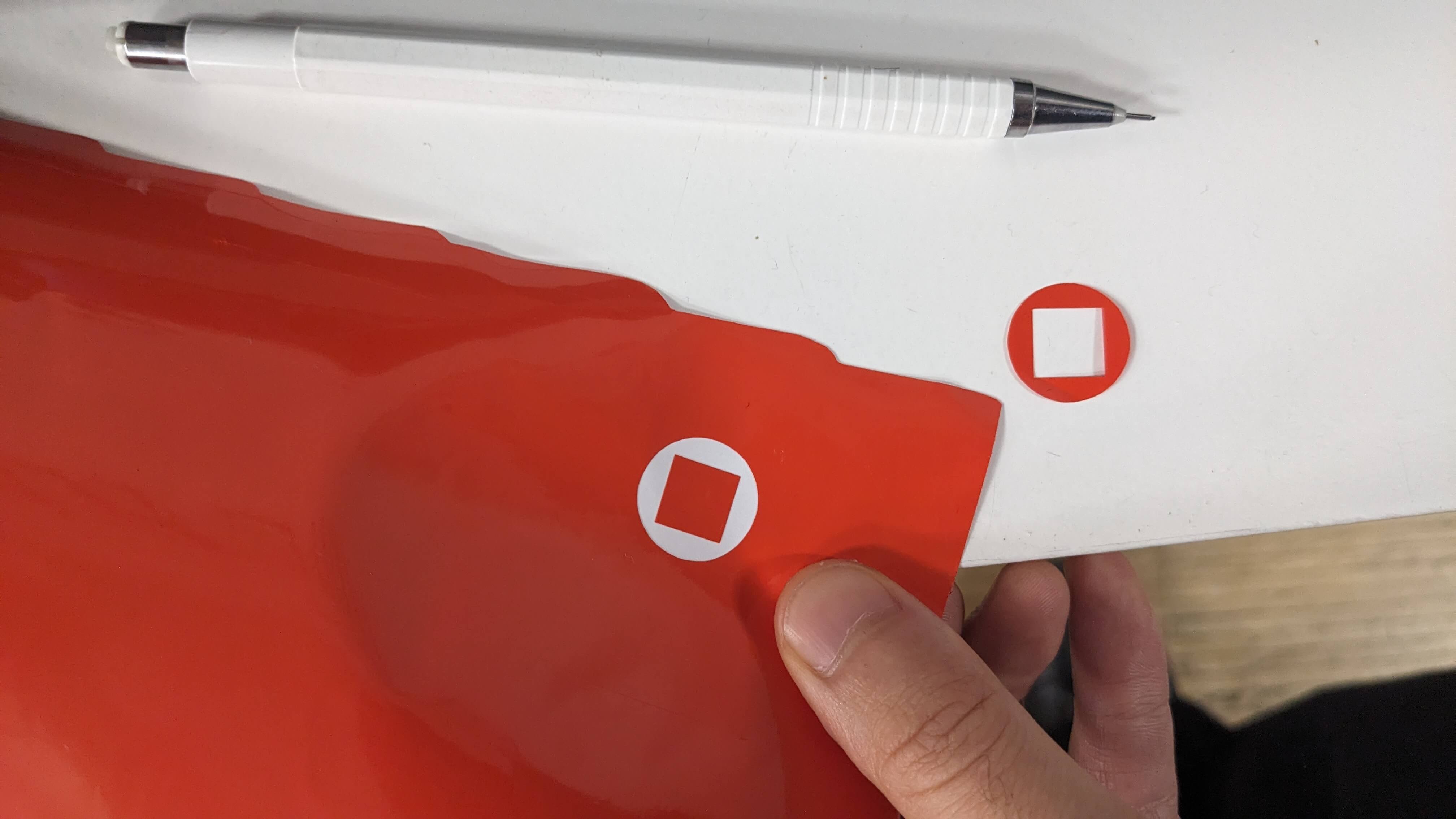
- Press Test to test cut the material
- Peel off the test piece (if the circle part comes out without a square, the setting is correct, if not adjust the speed and the pressure.)
- Move the cutting head by pressing the Origin and arrow keys
- Go to the computer and open the file
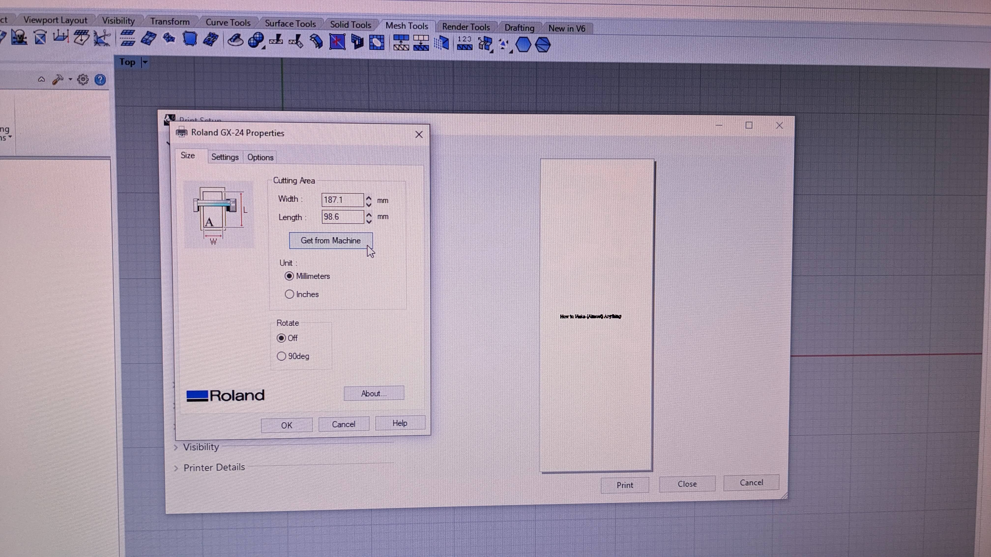
- Hit Print, make sure the machine is chosen as a printer, then hit Properties
- Hit Get from Machine to get the dimension measured by the machine
- Make sure the scale, view, and data type are correct
- Hit Window, and position the vector lines on the material by moving the working area
- Finally, hit Print
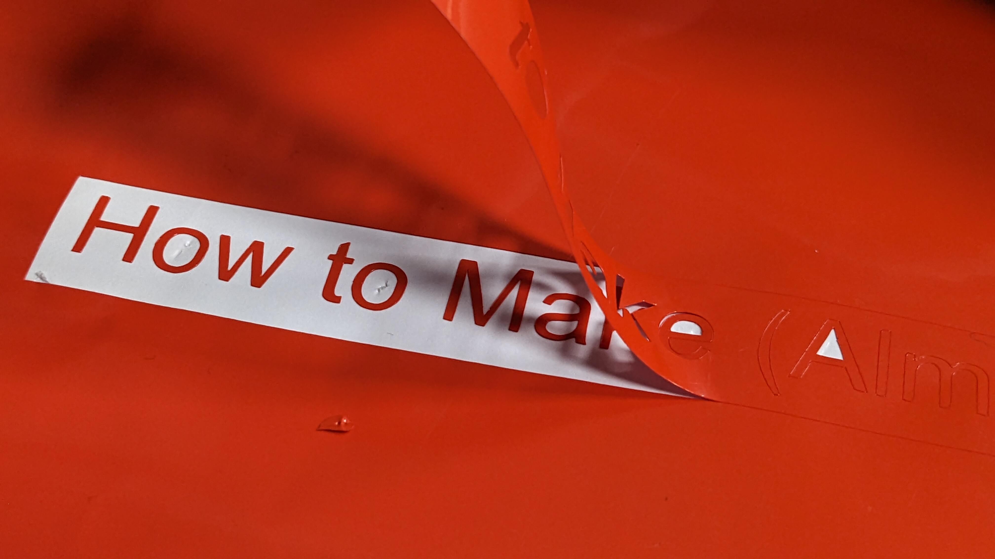
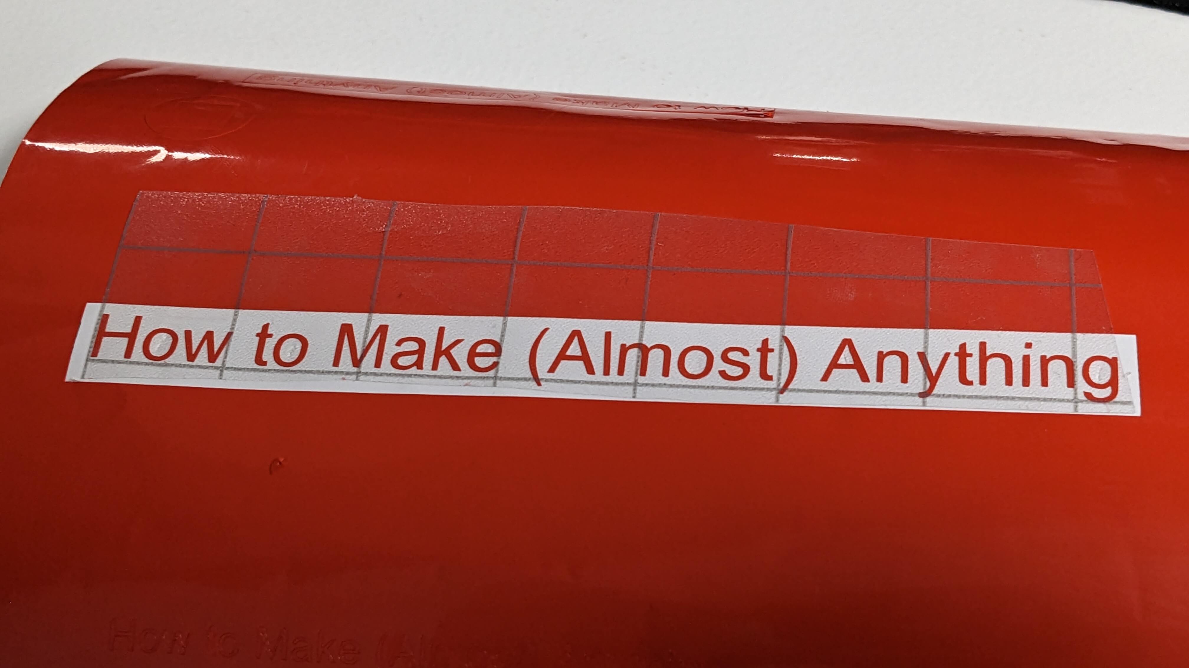
The outcome was successfully cut, however, because it was a series of characters, it was painful to peel off the void pieces. After removing those void pieces, I used a transferring sheet to transfer the vinyl to my sketchbook, but again it was painful to stick thin pieces to the transferring sheet. Anyway, I was able to have the “How to Make (Almost ) Anything” vinyl stuck on the front cover of my sketchbook (also I stuck the offcut to my laptop as well)
Files
VinylCut_CUT.3dm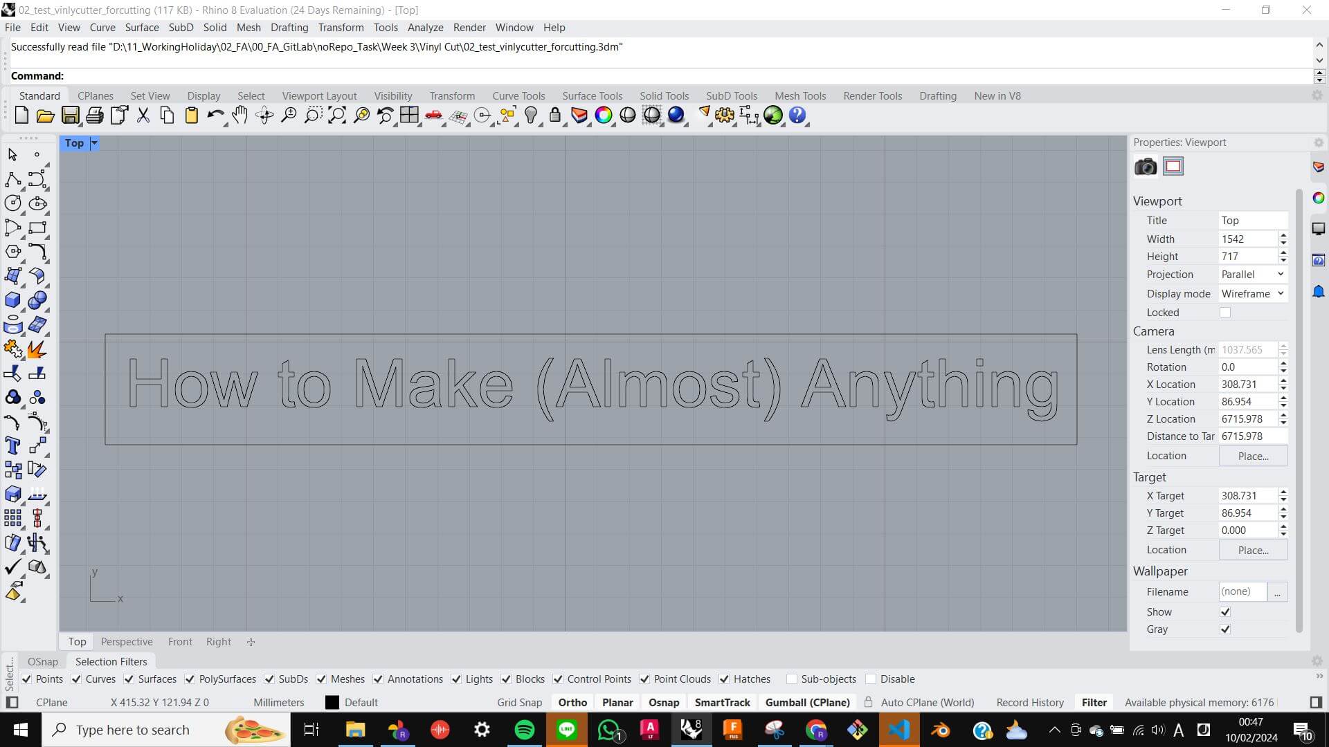
Press Fit Kit
Parametric Modelling
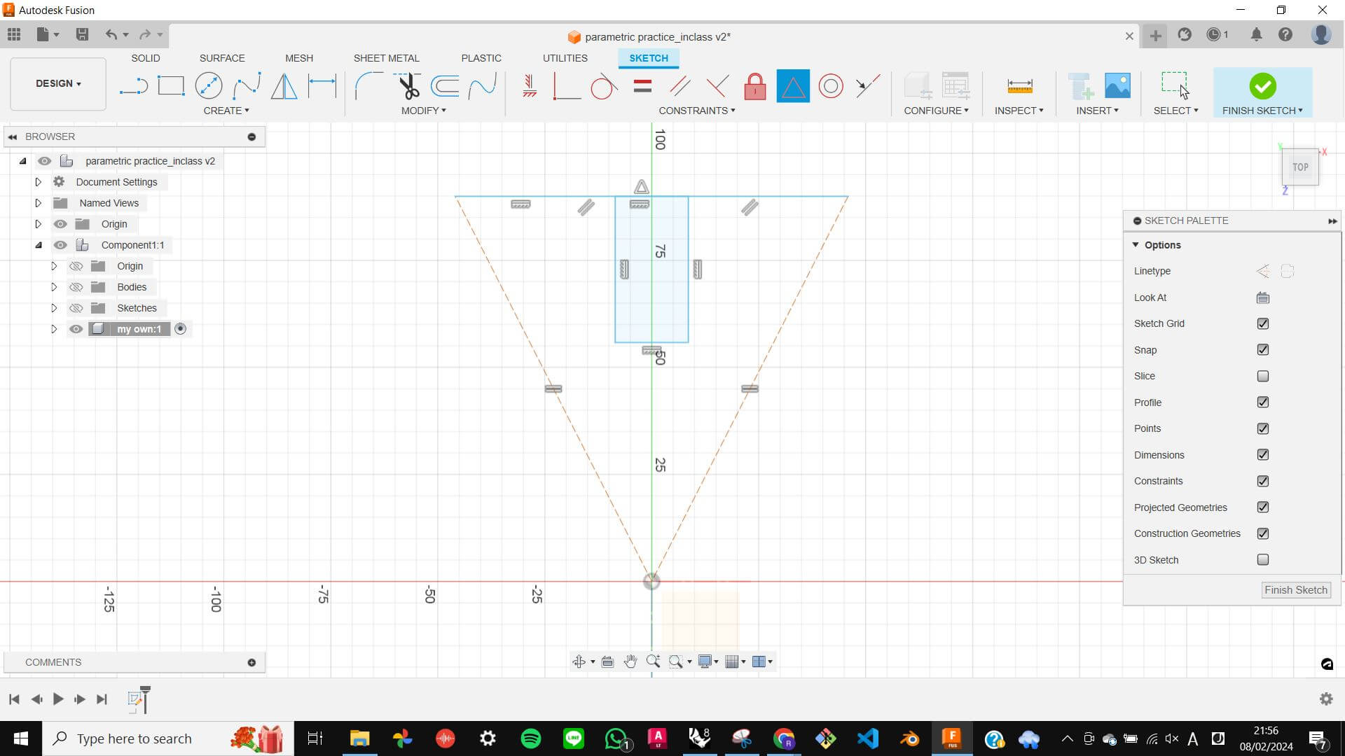
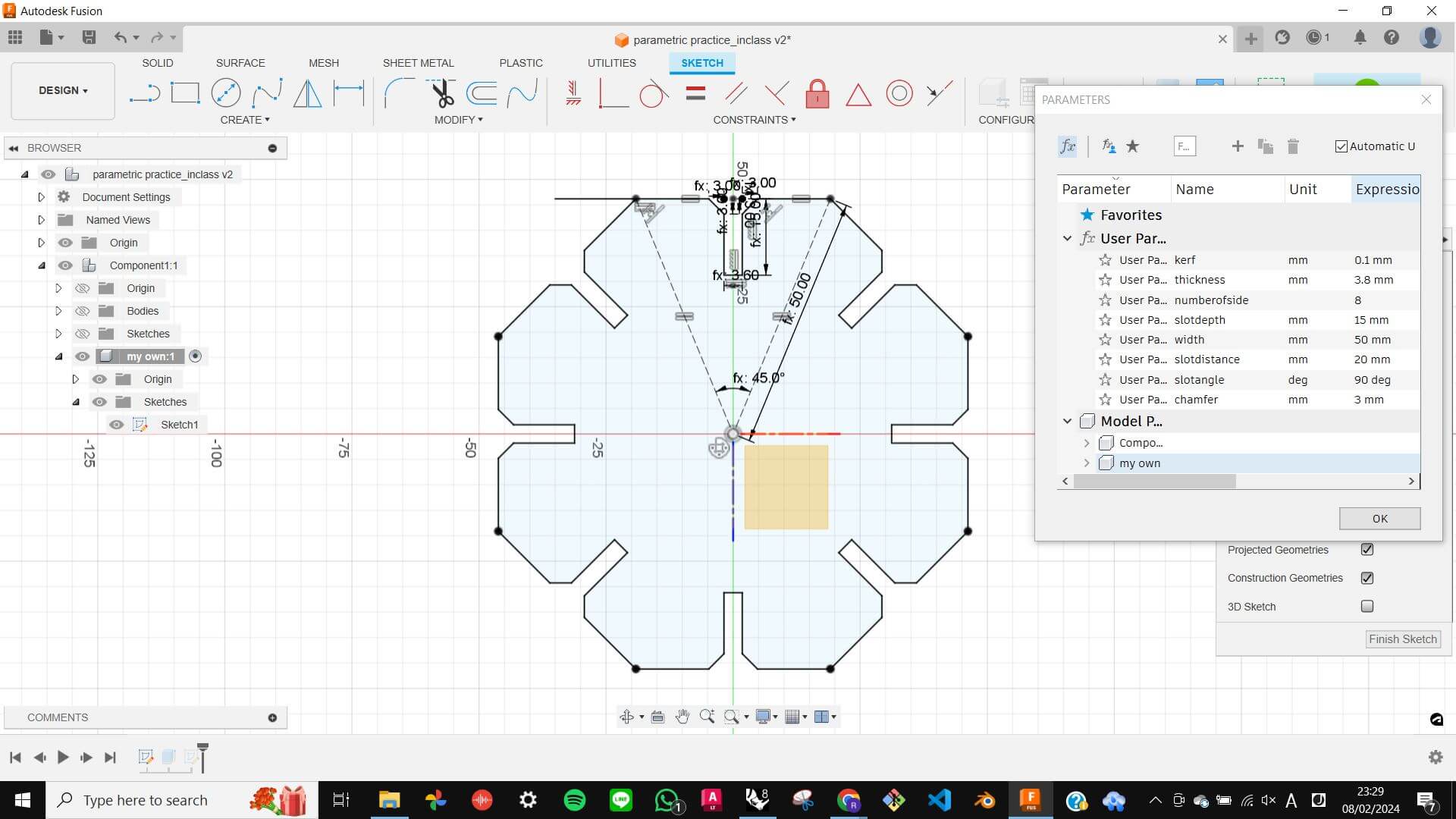
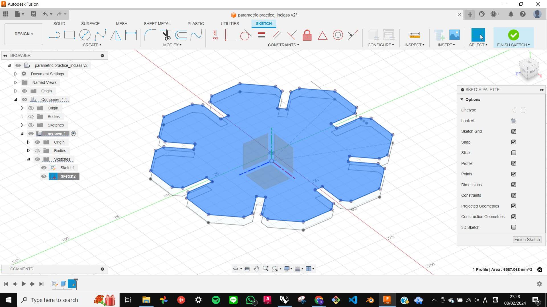
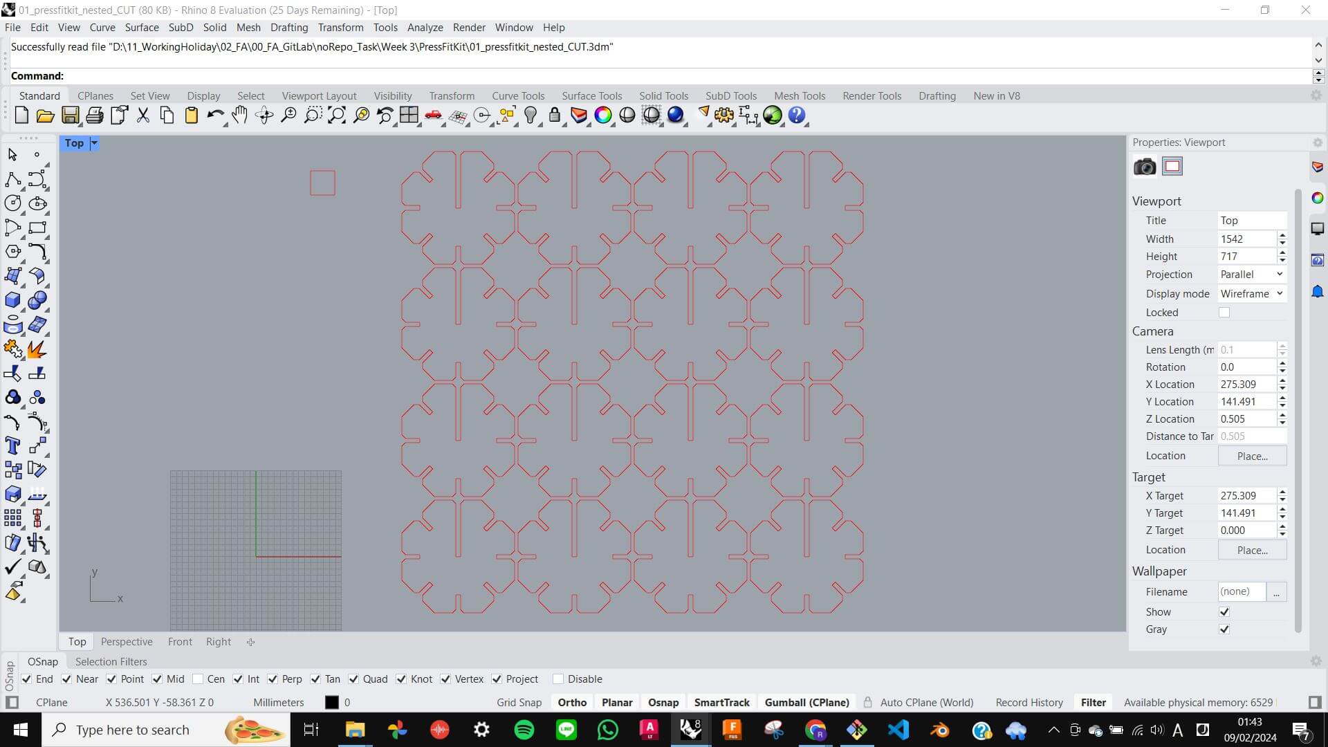
This was an assignment to make a press-fit kit with parametric modelling and a laser cutter. To create a parametric model, I decided to use Fusion 360 because it seems very straightforward to work with. The workflow of parametric modelling is very different to normal modelling. First I needed to think about what kind of parameter I needed to create the shape I wanted, then set parameters with a label for each parameter such as Kerf, Slot Depth, Thickness, Number of Side, etc. Next, I insert the basic shape which is suitable for the parameterising process, this time I used a triangle. Next, I constrain some objects that I don't want to be affected when parameters change, such as equal, parallel, perpendicular, and position. Then I finally set the dimensions of objects with parameters by using the dimension tool. Especially for the slot width, I used the equation (Thickness - Kerf*2), so that I can later use the parameter even when material thickness changes. Once, the triangle was ready to be arrayed, I used a circular pattern tool to make an Octagon. In this process, I also used a parameter with an equation (360/Number of Side)-1deg, so that geometry can be adjusted only with a parameter. Before I exported the shape, I extruded the sketch to create a solid model, then a project tool to get the surface to easily select the vector line. Finally, I exported the vector data by Save as DXF to transfer to Rhino. In Rhino, I simply nested the Octogon and prepared the file data specially for the laser cutting.
Laser Cutting
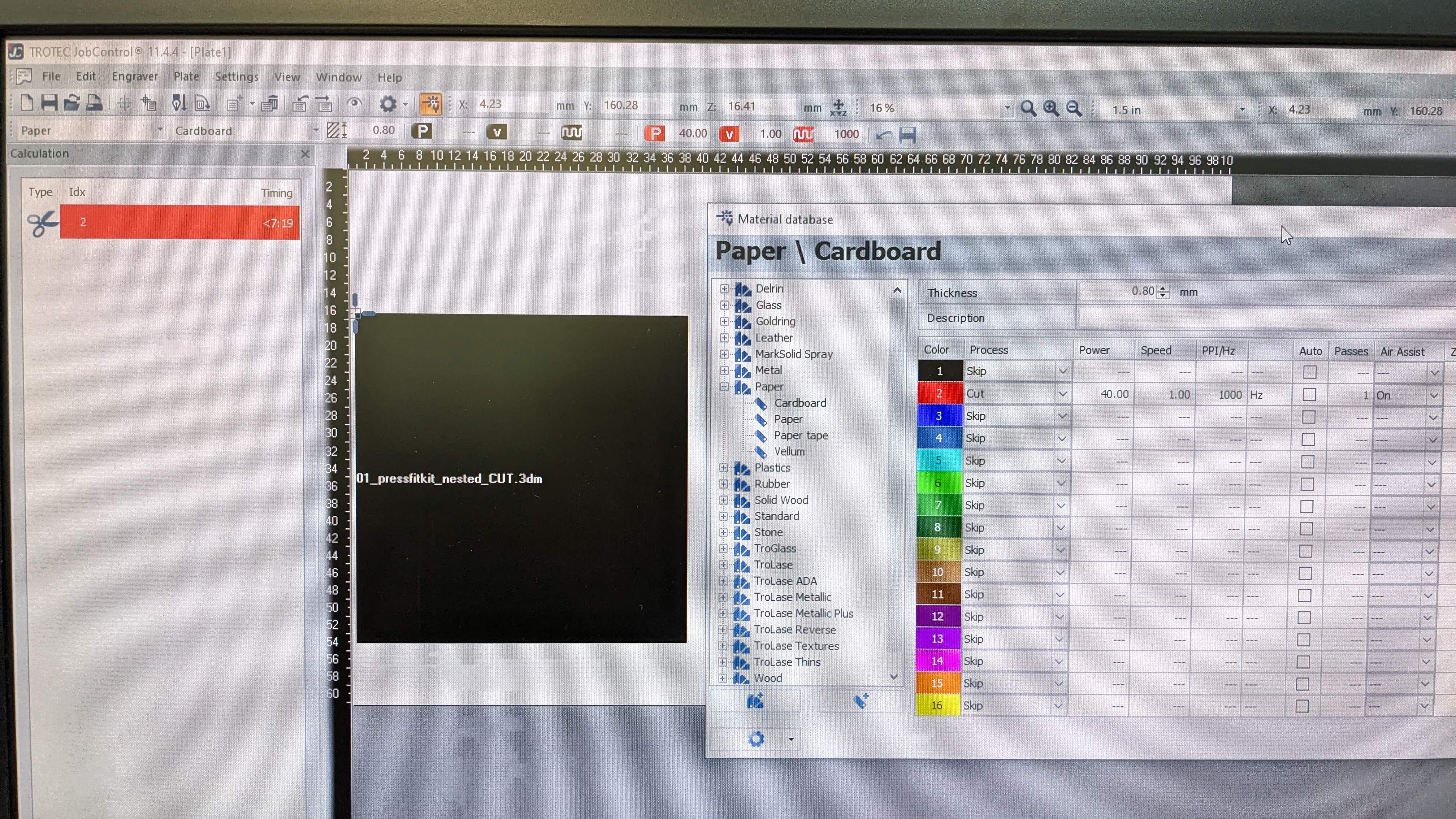
For laser cutting, I simply repeated the process I learned from the group assignment. Also, for the material, I decided to use the same cardboard from the group assignment, because I felt comfortable with it and it seemed suitable for quick testing.
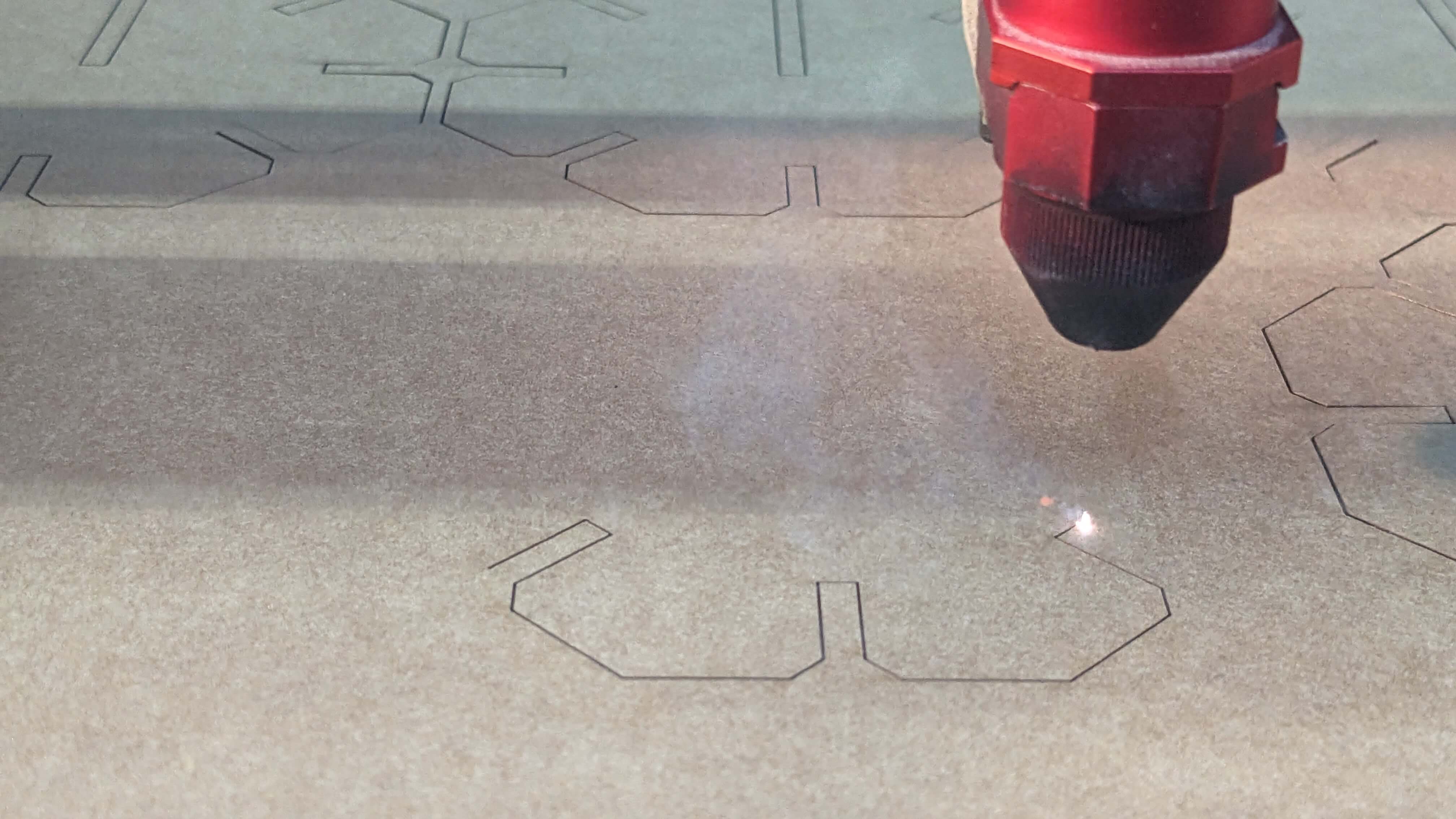
As the outcome, the octagons were nicely cut and the slot worked very precisely. However, If I were to do it again, I would make slots a little bit wider because it was pretty tight. The best thing about this model is that I can easily make the change by adjusting only one parameter.
Files
PressFitKit_piece.dxf PressFitKit_CUT.3dm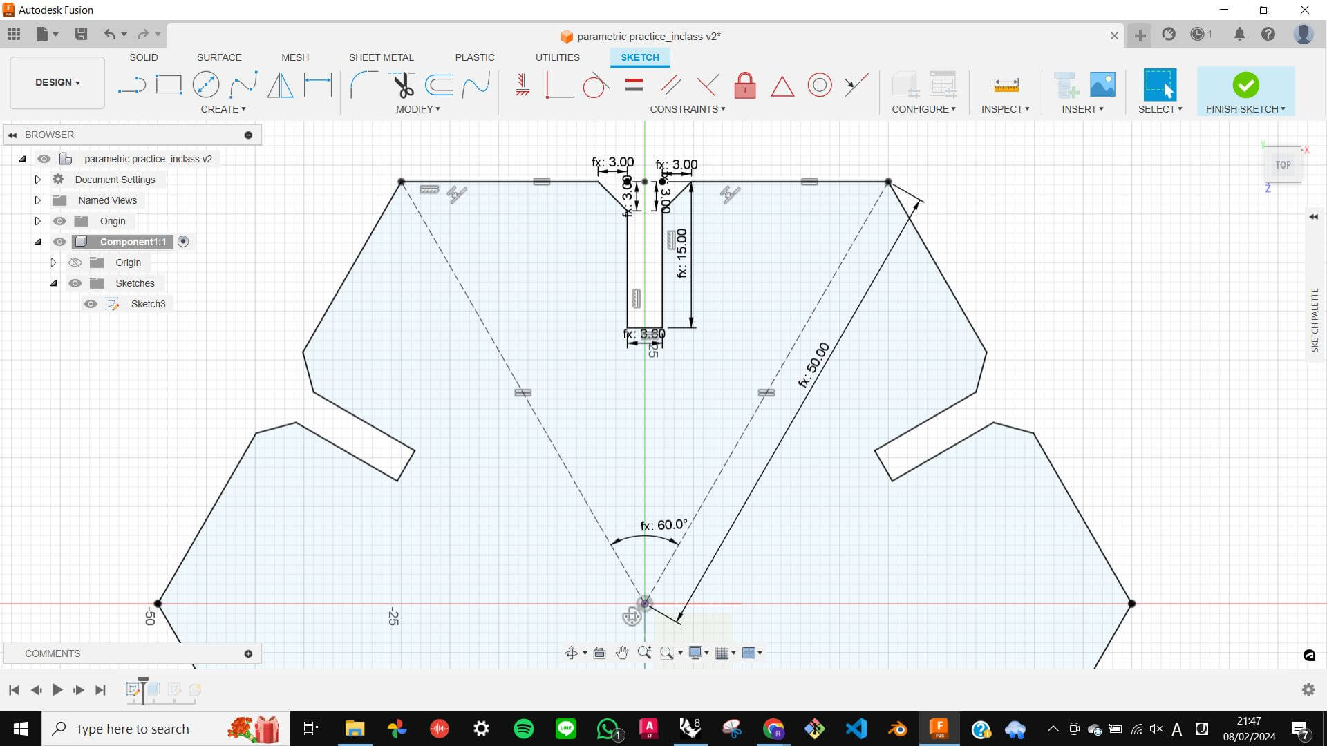
Living Hinge Test
Since my final project focuses on a movement, I wanted to try making Living Hinge. (Also because I have seen living hinge a lot in the architecture discipline, I always wanted to experiment with it)
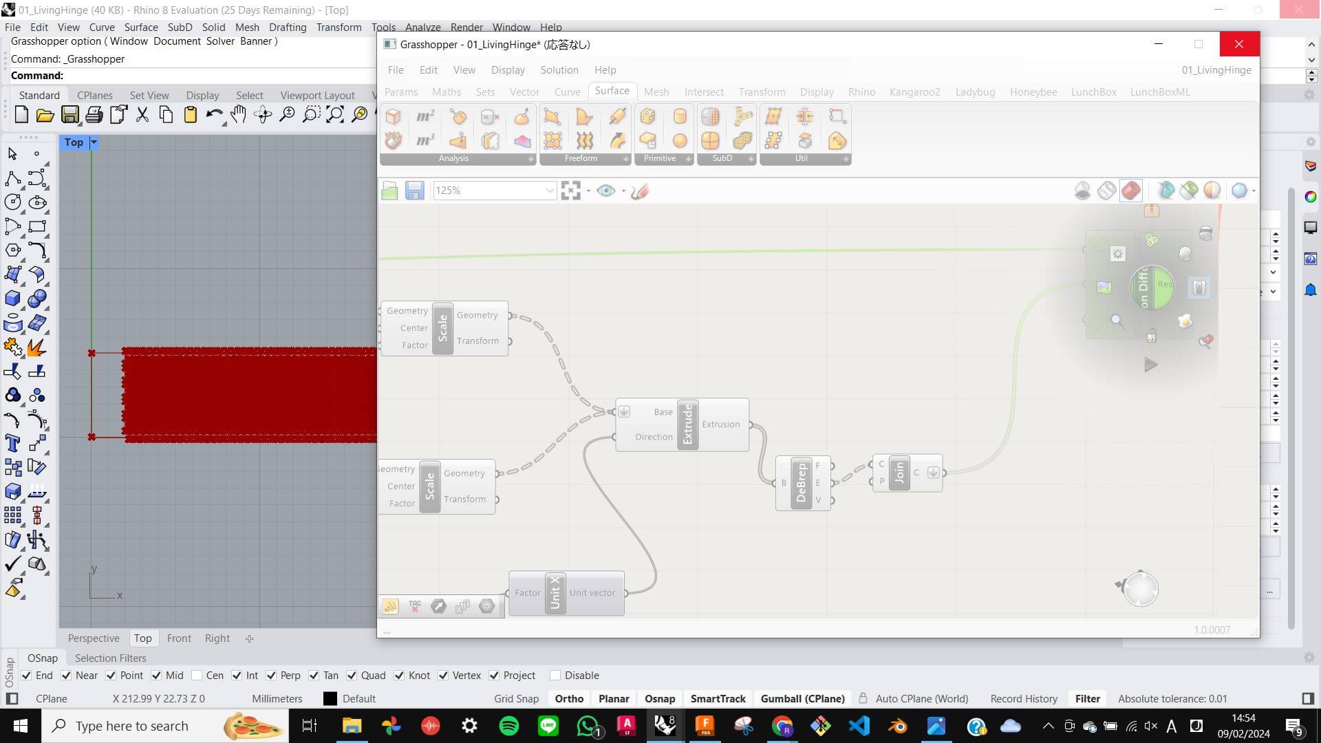
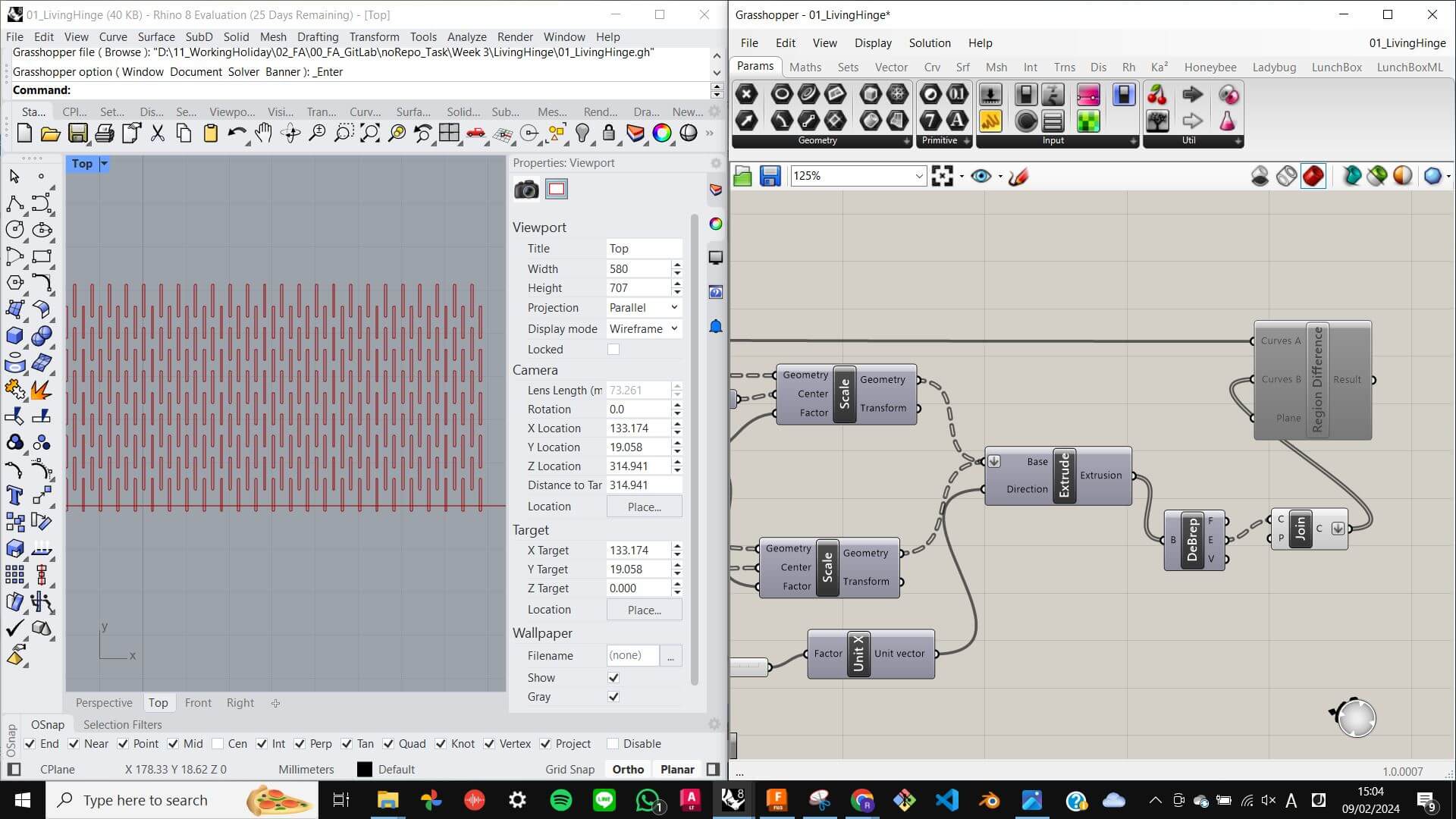
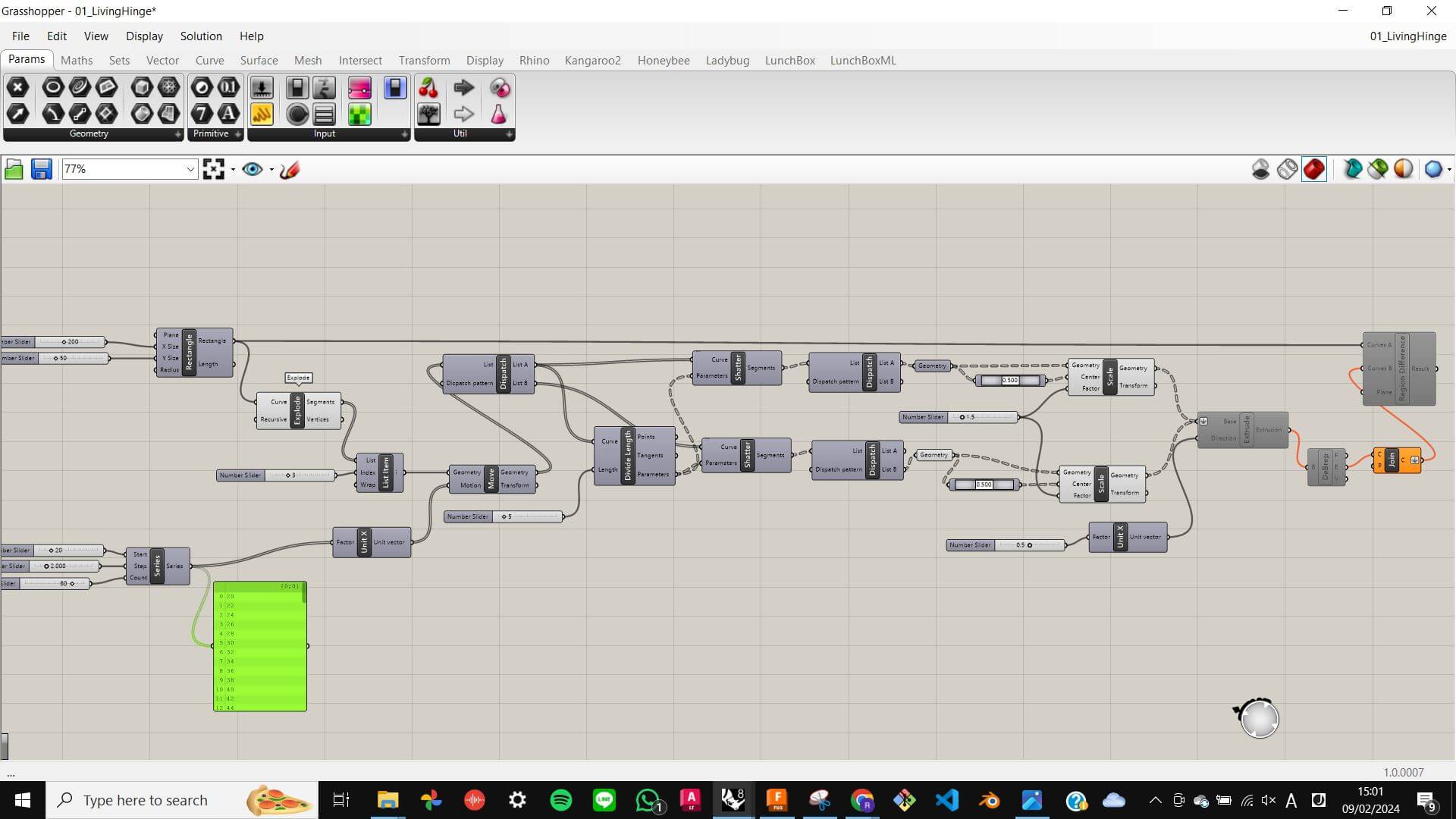
For me to get my hands on the parametric making of Living Hinge, I started with understanding the grasshopper node template which was prepared by my tutor. It was quite difficult to get my head around the node equation, but with help from my tutor, I briefly understood the node process and what parameters I needed to adjust to create the model I wanted.
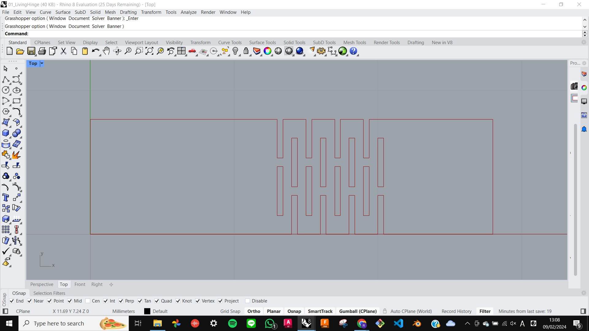
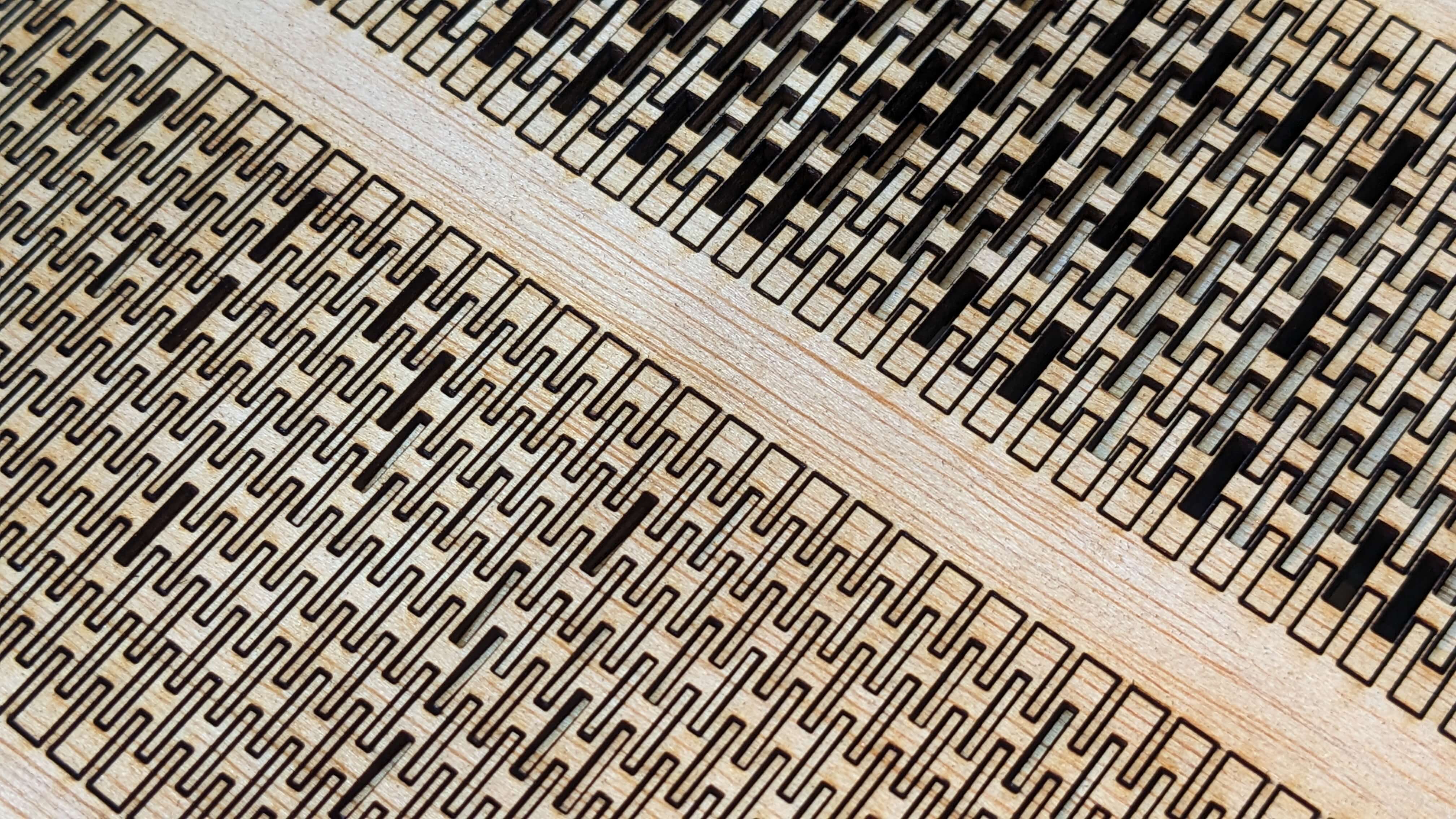
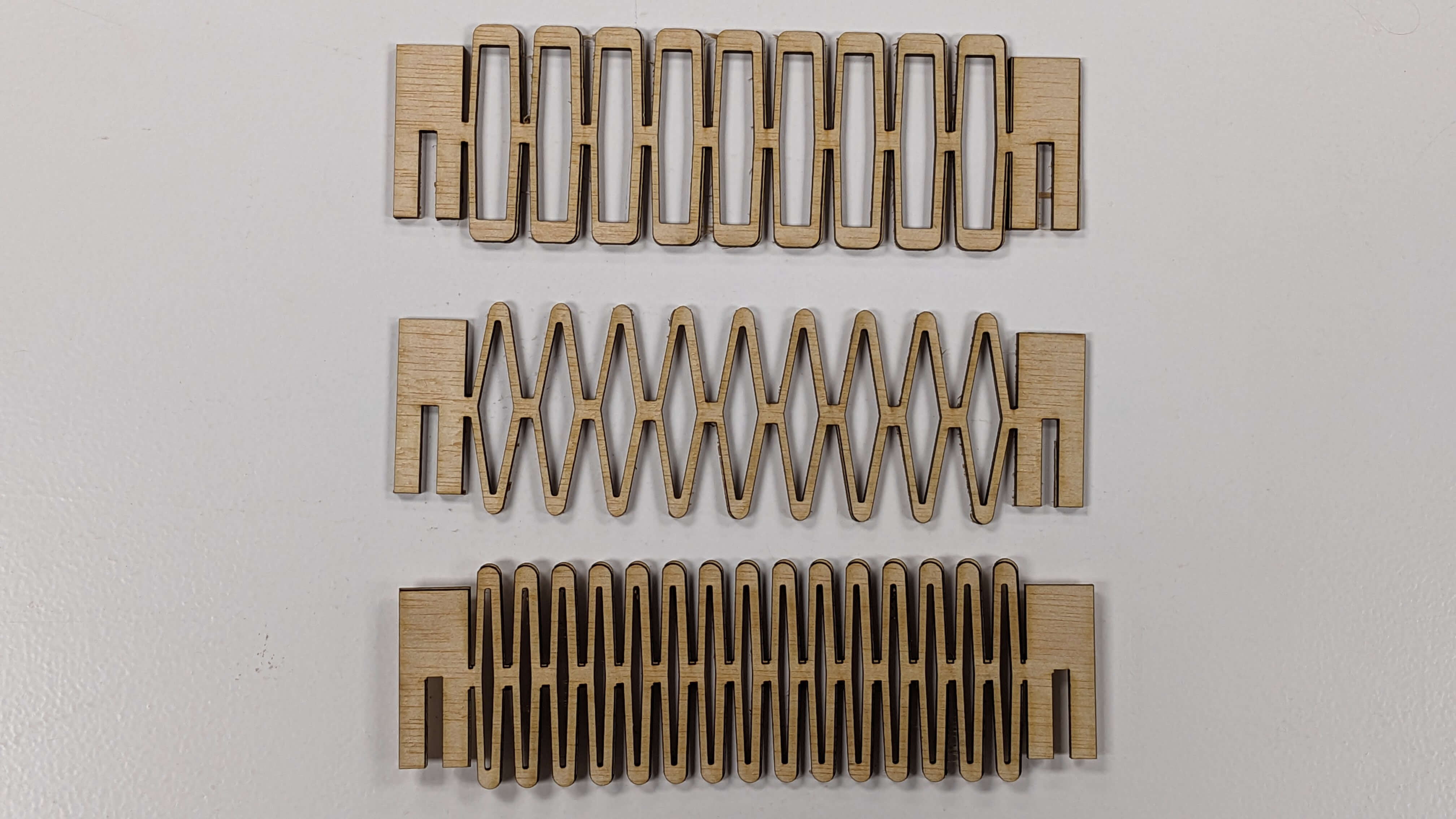
I set the dimensions for a base rectangle to be 200mm x 50mm, and offset the hinge area by 20mm on each side. As the gid for the hinge structure, I set 80 grids with 1mm spacing. To create the hinge pattern, I tweaked the parameters for division and hollow size. I created 6 test models with 3 types of division (1/2 1/5 1/10) and 3 types of hollow size (0.5, 1.0, 1.5)
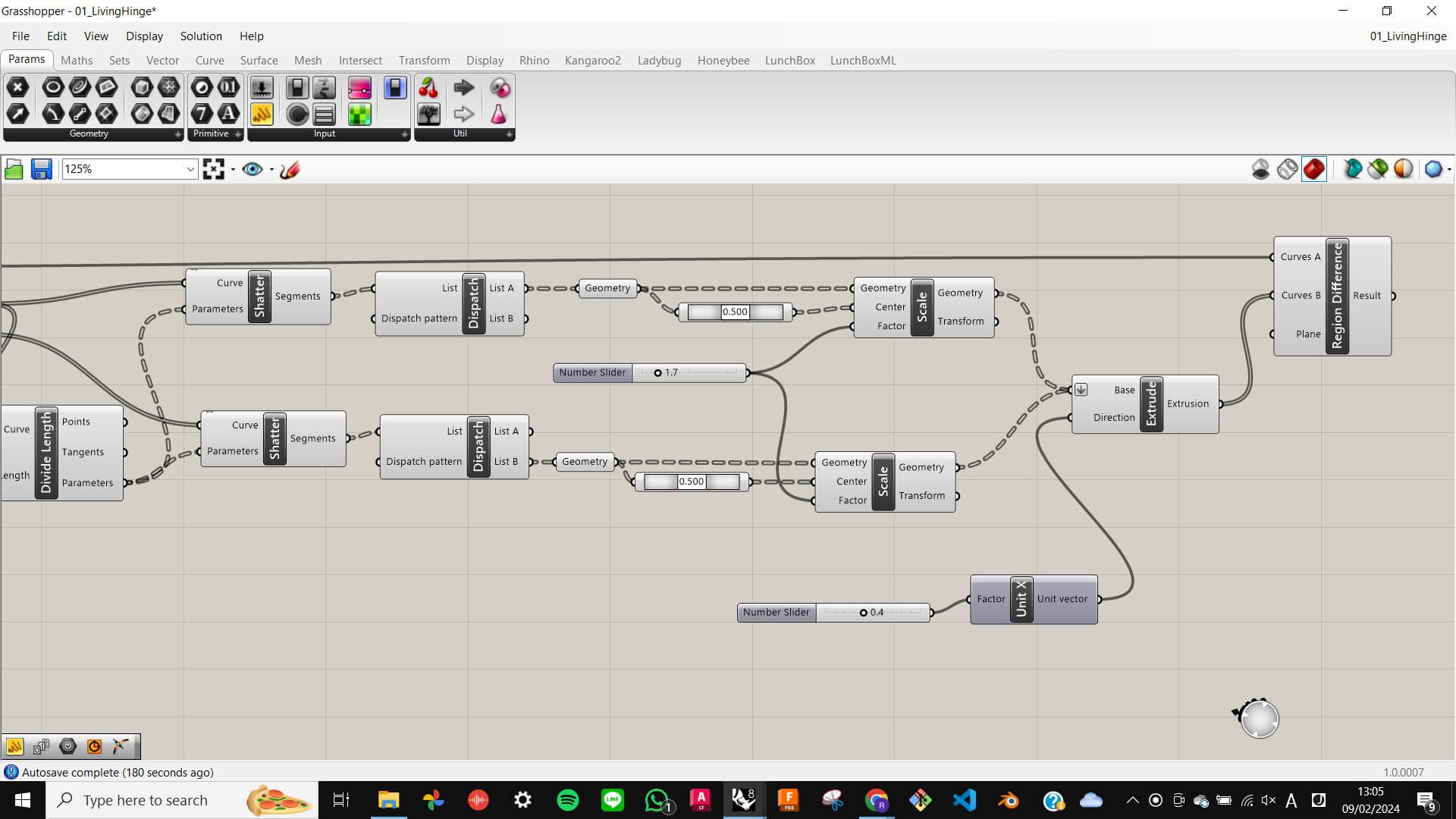
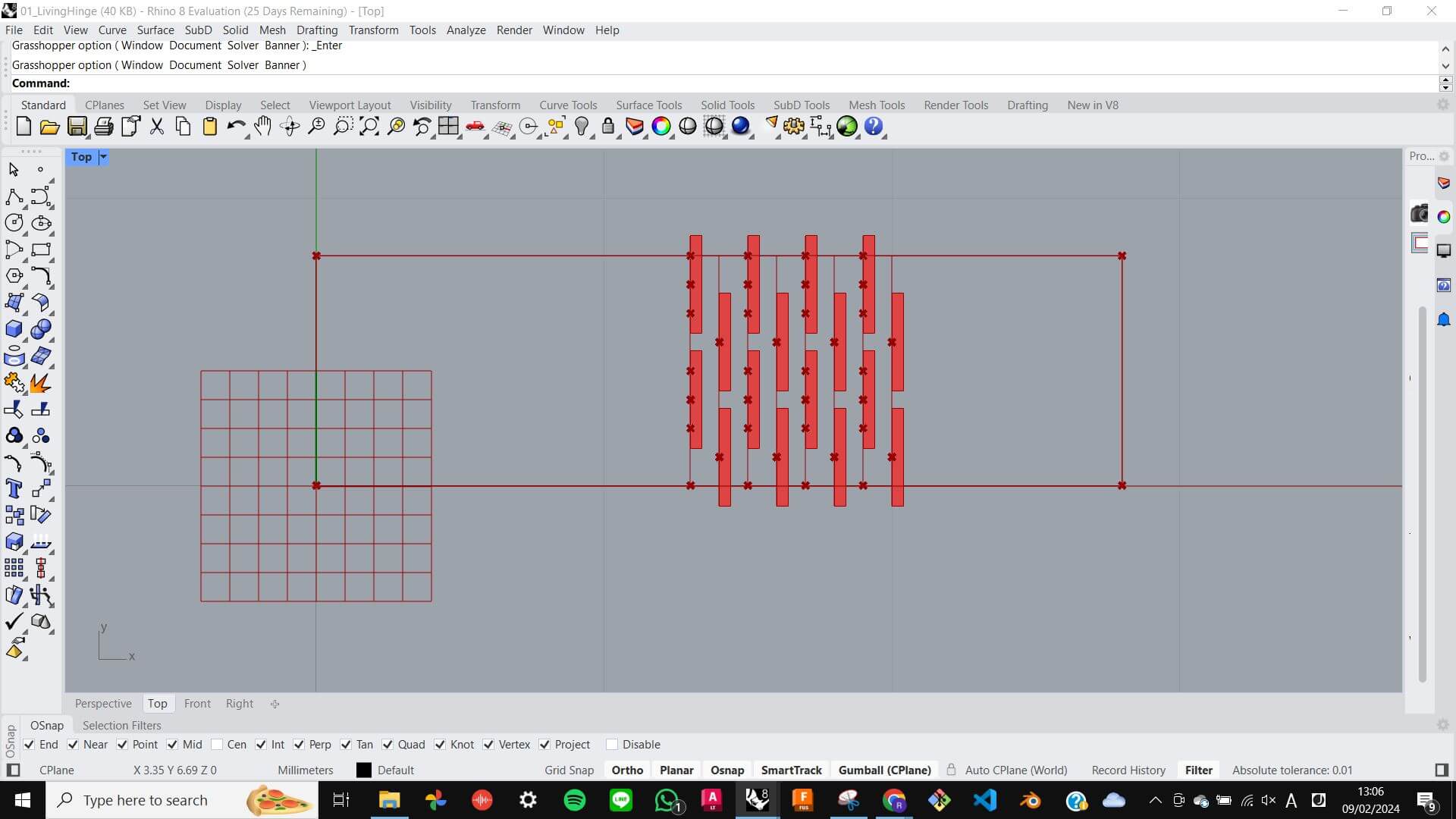
Problem
When I was setting up parameters in Grasshopper, I experienced a serious delay when I set parameters high value. Because those values were necessary to achieve the size and density of my test model, I needed to figure out a solution without changing the value. With my tutor's help, I figured out the cause of the problem and how to avoid the problem. The cause was that Grasshopper kept doing boolean differences between the base rectangle and hinge pattern as I changed parameters, so the solution for this problem was to deactivate the boolean difference function until the parameters were set. However, this problem was not fully solved because I still needed to activate the boolean difference function before I bake which was not possible due to the heavy calculation load. Instead, I decided to back the base rectangle and hinge pattern separately, and then boolean difference manually on Rhino which was a very time-consuming task. This was only a get-by solution, so I like to find a way to reduce the calculation load and do everything in
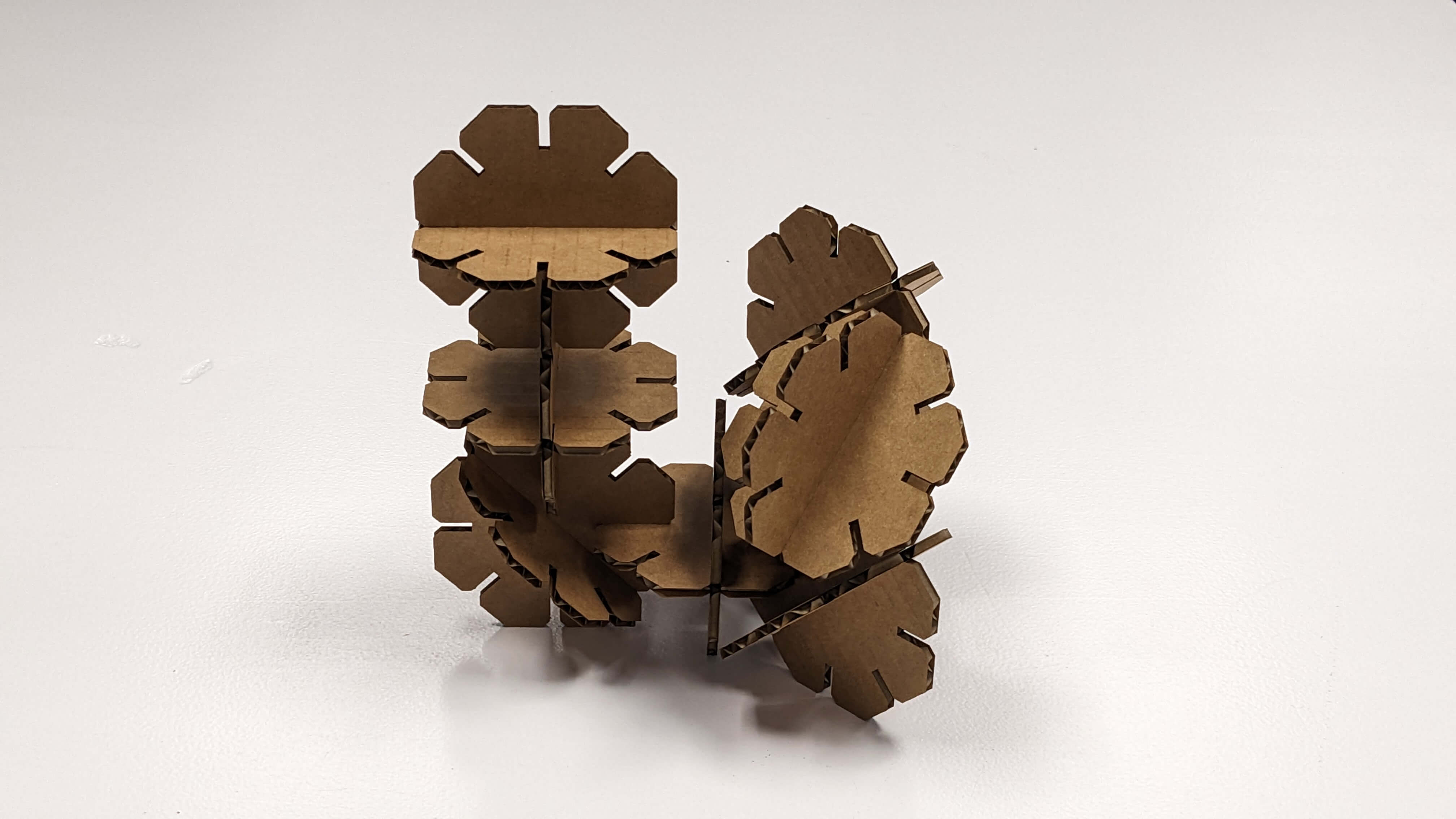
Living Hinge Test : Result
Files
LivingHinge.gh LivingHinge_CUT_25.3dm LivingHinge_CUT_10.3dm LivingHinge_CUT_5.3dm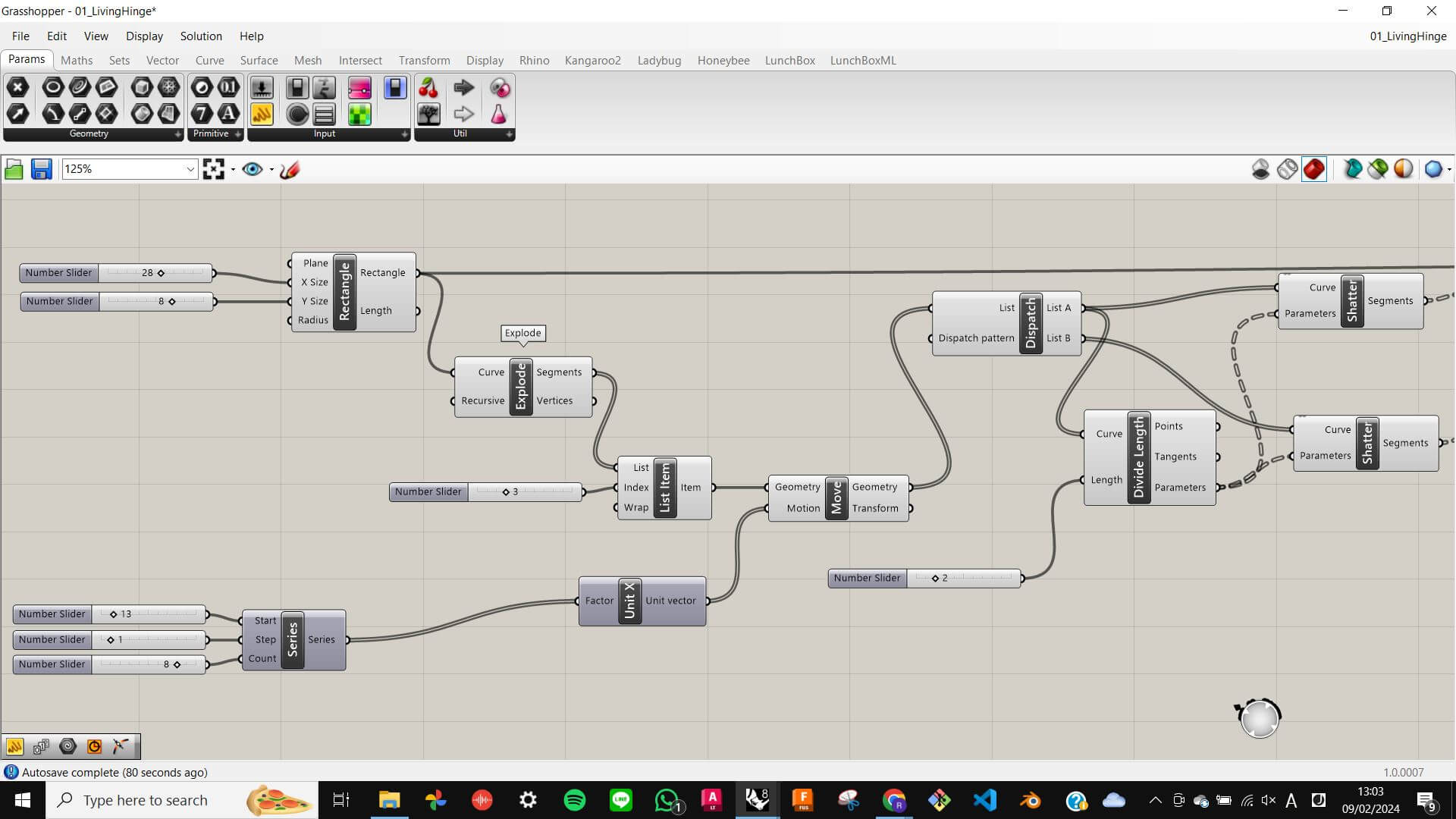
Living Hinge Test: Result
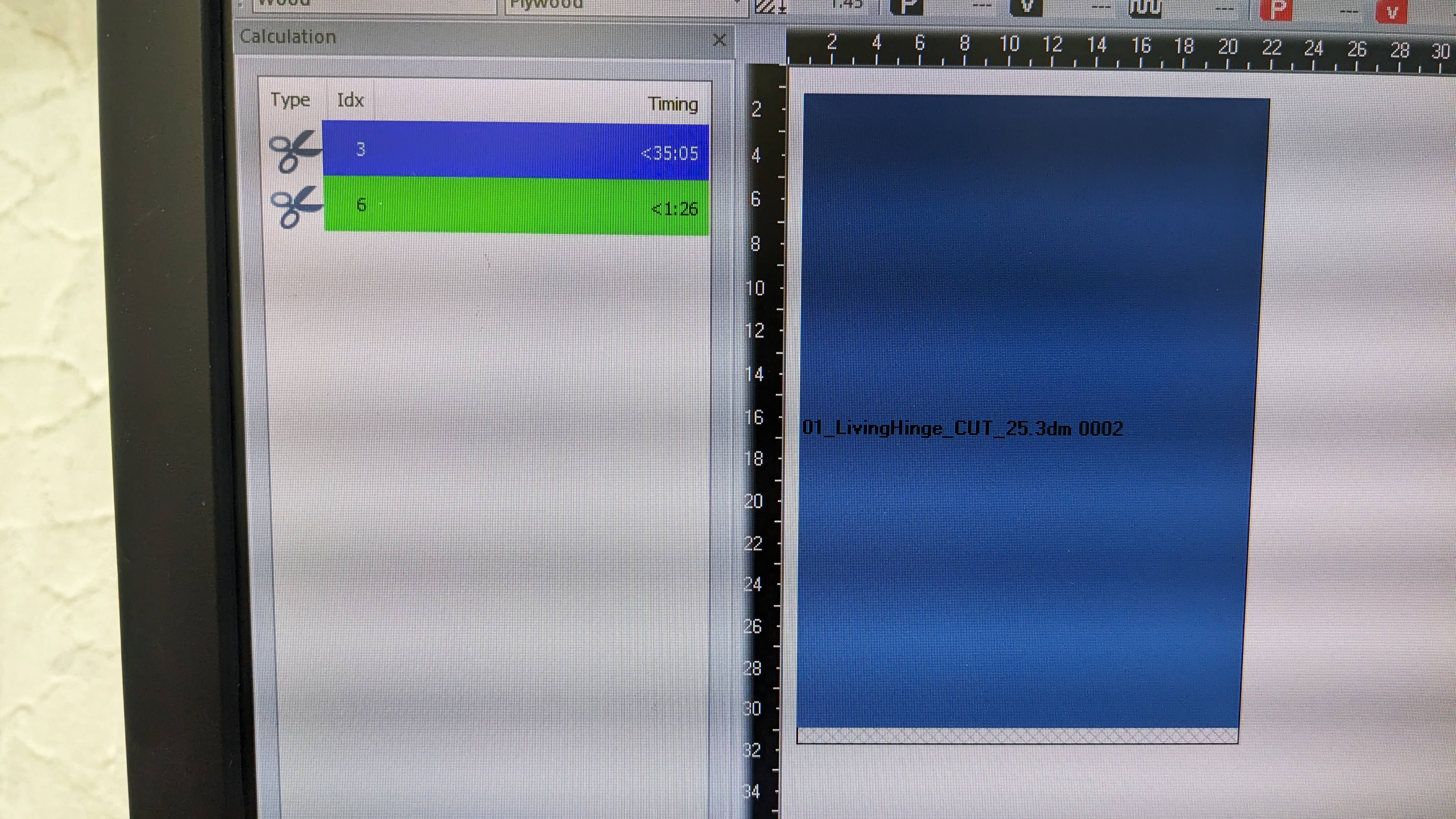
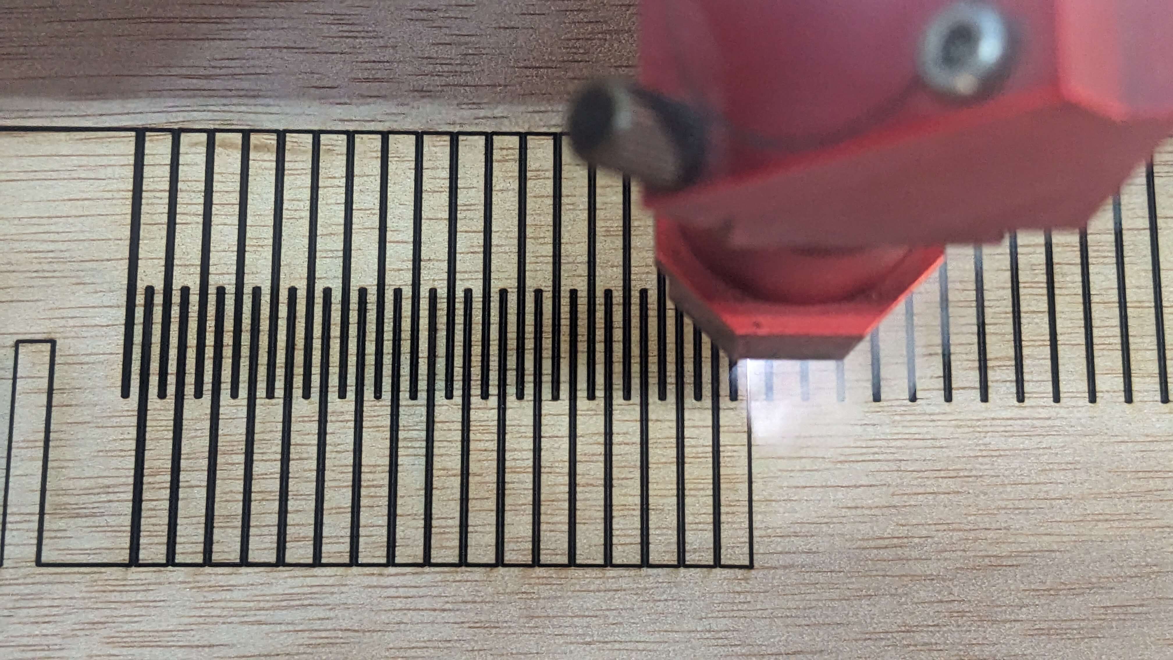
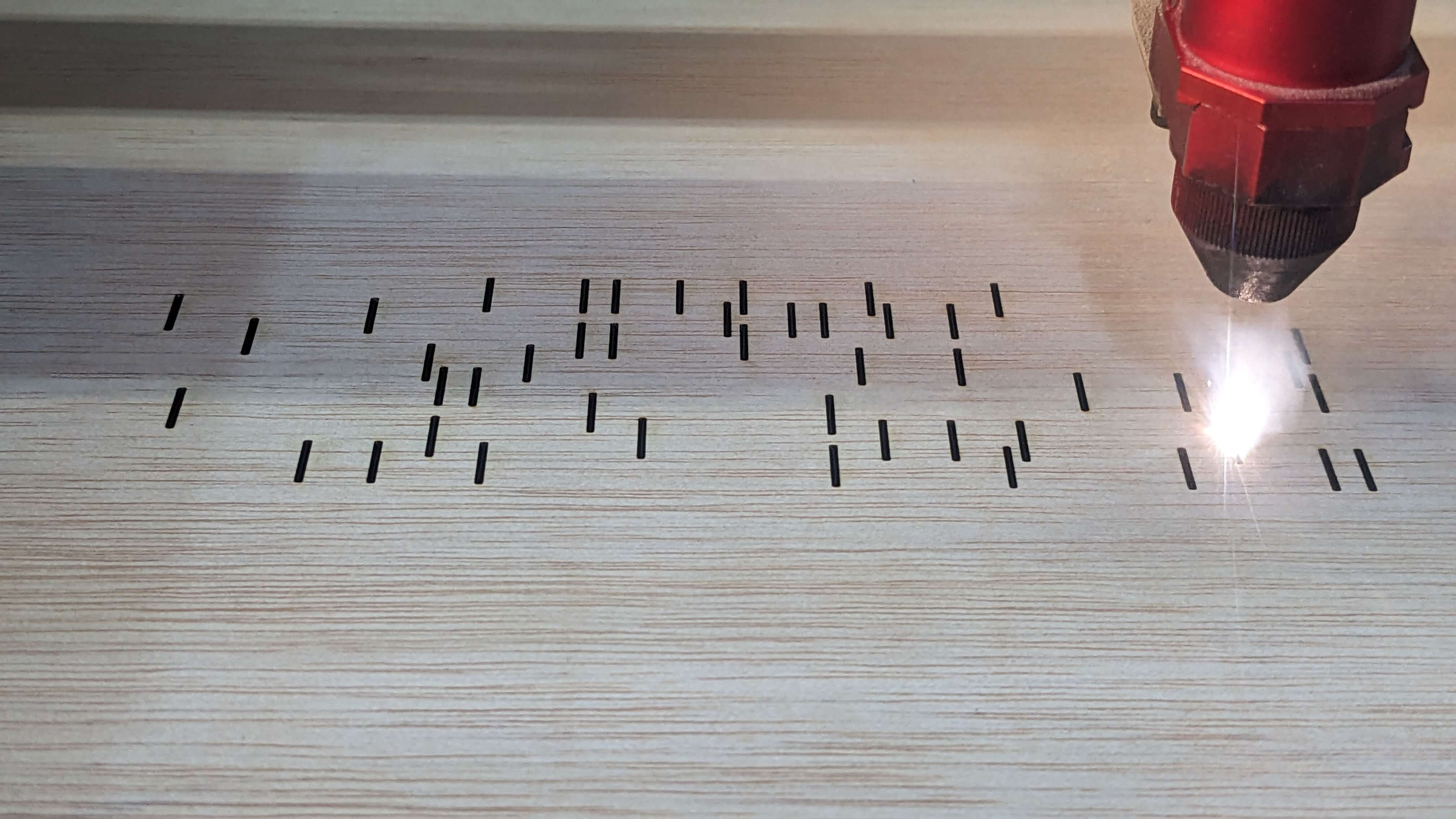
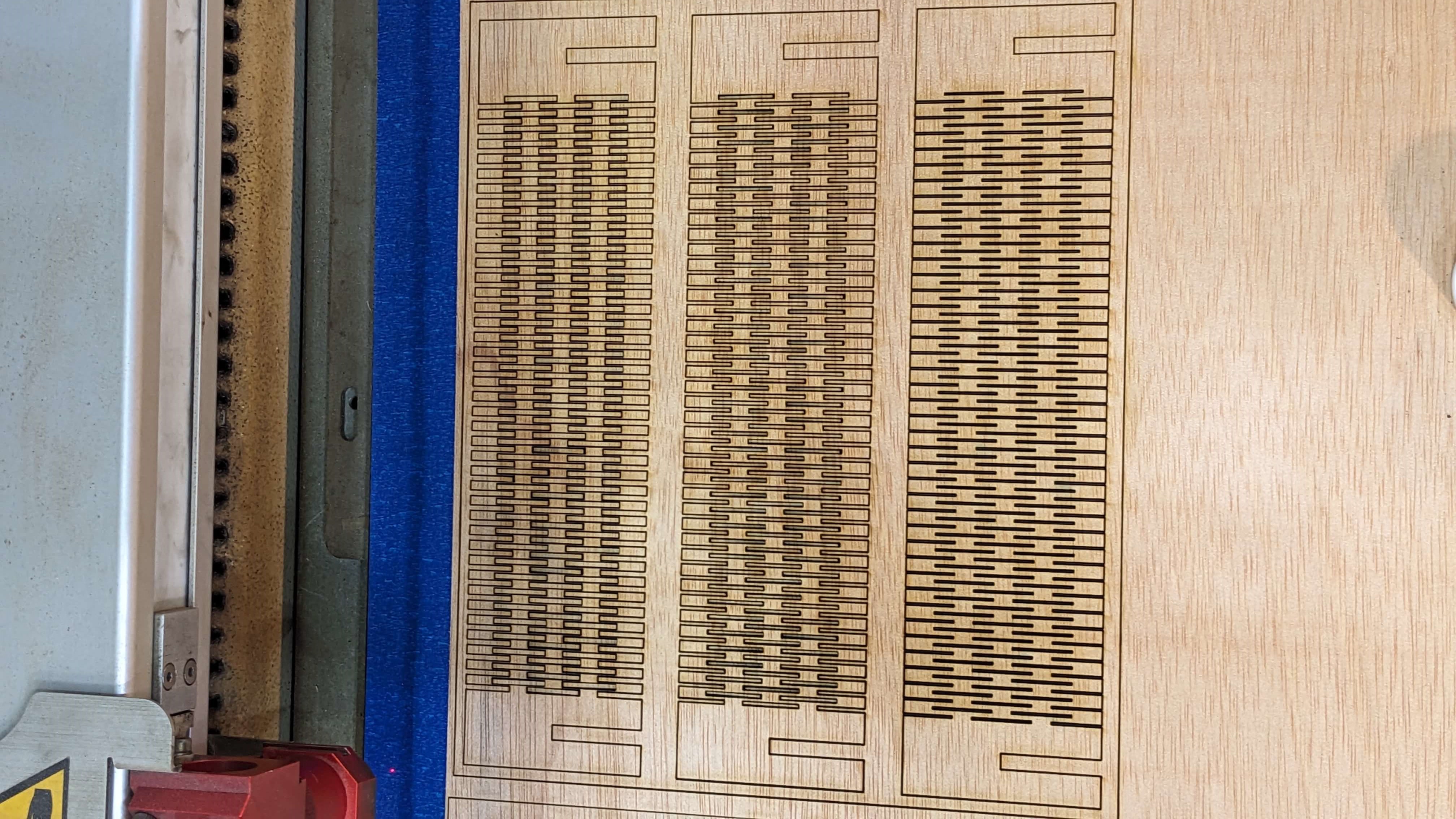
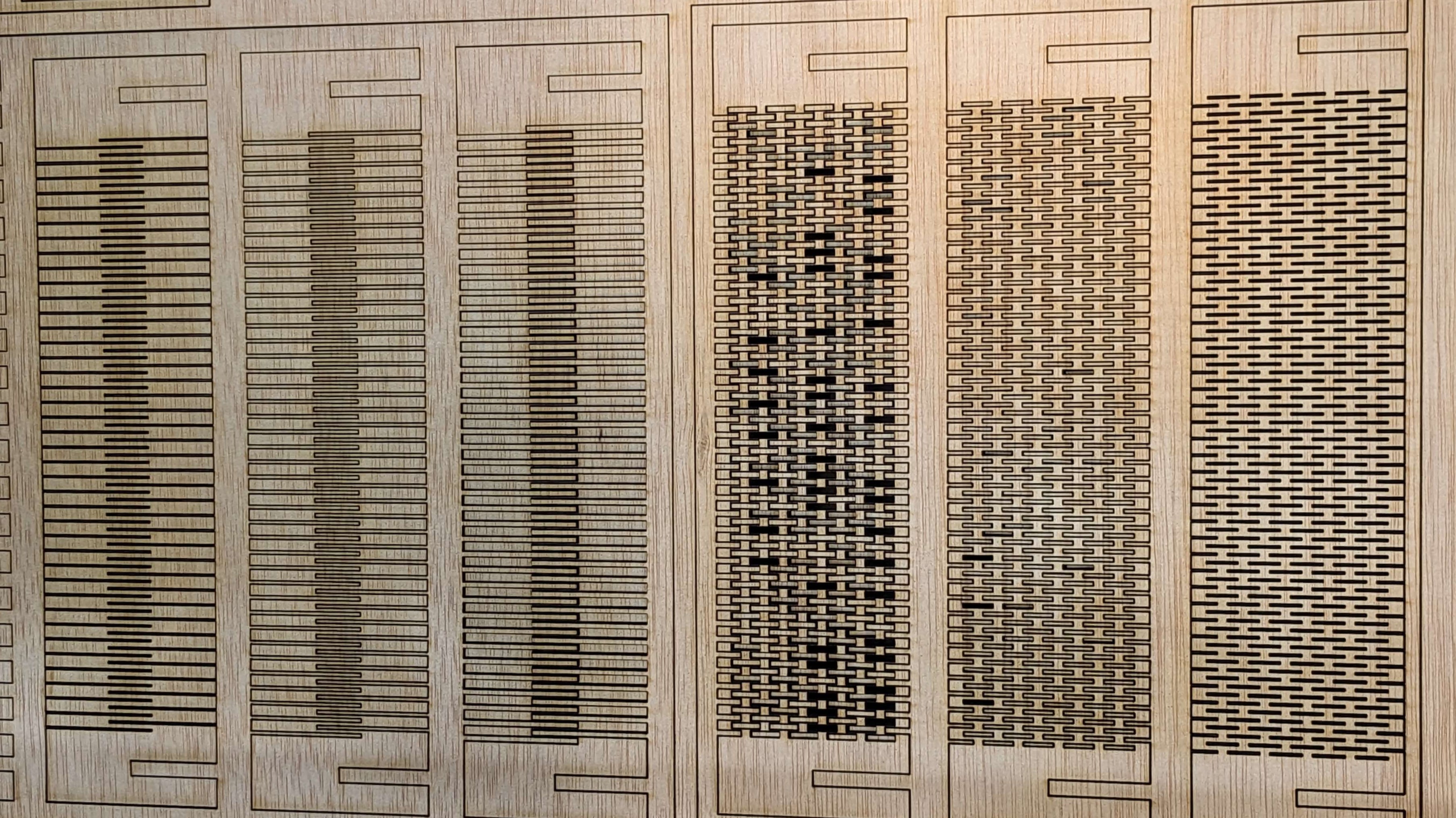
I was able to laser cut all of the living hinges successfully, however, It took around 20 min for each three hinges to laser cut. This was due to the dense pattern that I made. Especially those parts that I used 0.5mm as a value for the thickness of the ribs.
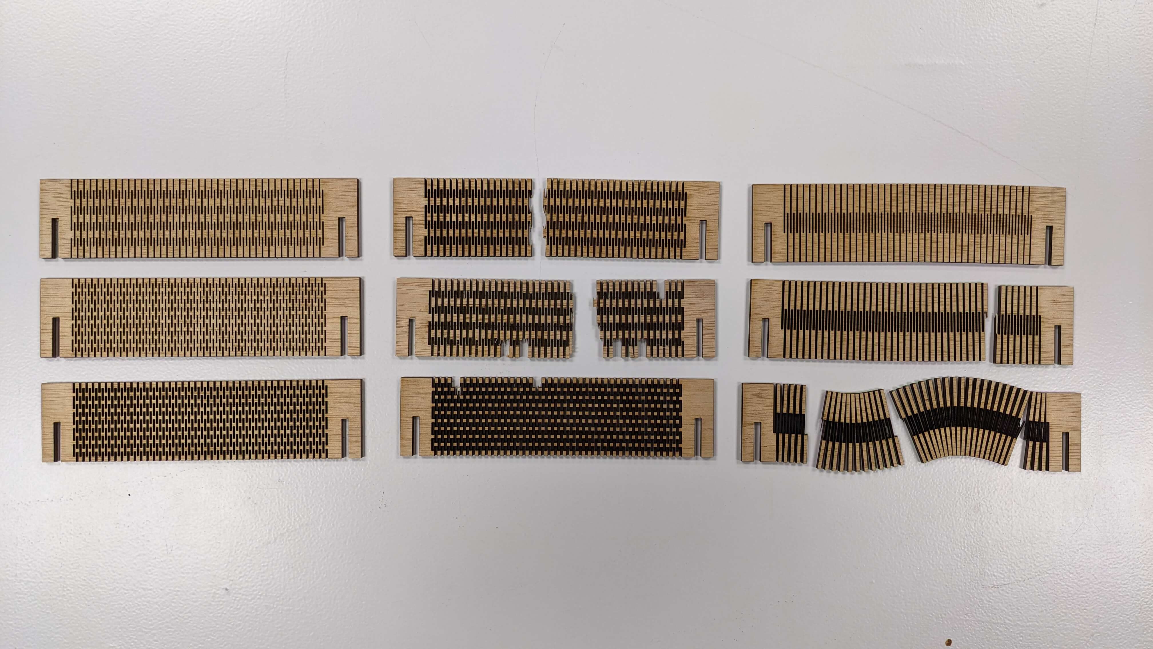
2 Divisions
These living hinges are made of 2 divisions and 3 different thicknesses of the ribs( top 0.5mm, middle 1.0mm, bottom 1.5mm). As you can see in the photo apart from 1.5mm ribs, broke in the process of laser cutting and bending test. A lesson from this test is that, when the thickness of ribs is under 1.5, it becomes significantly fragile.
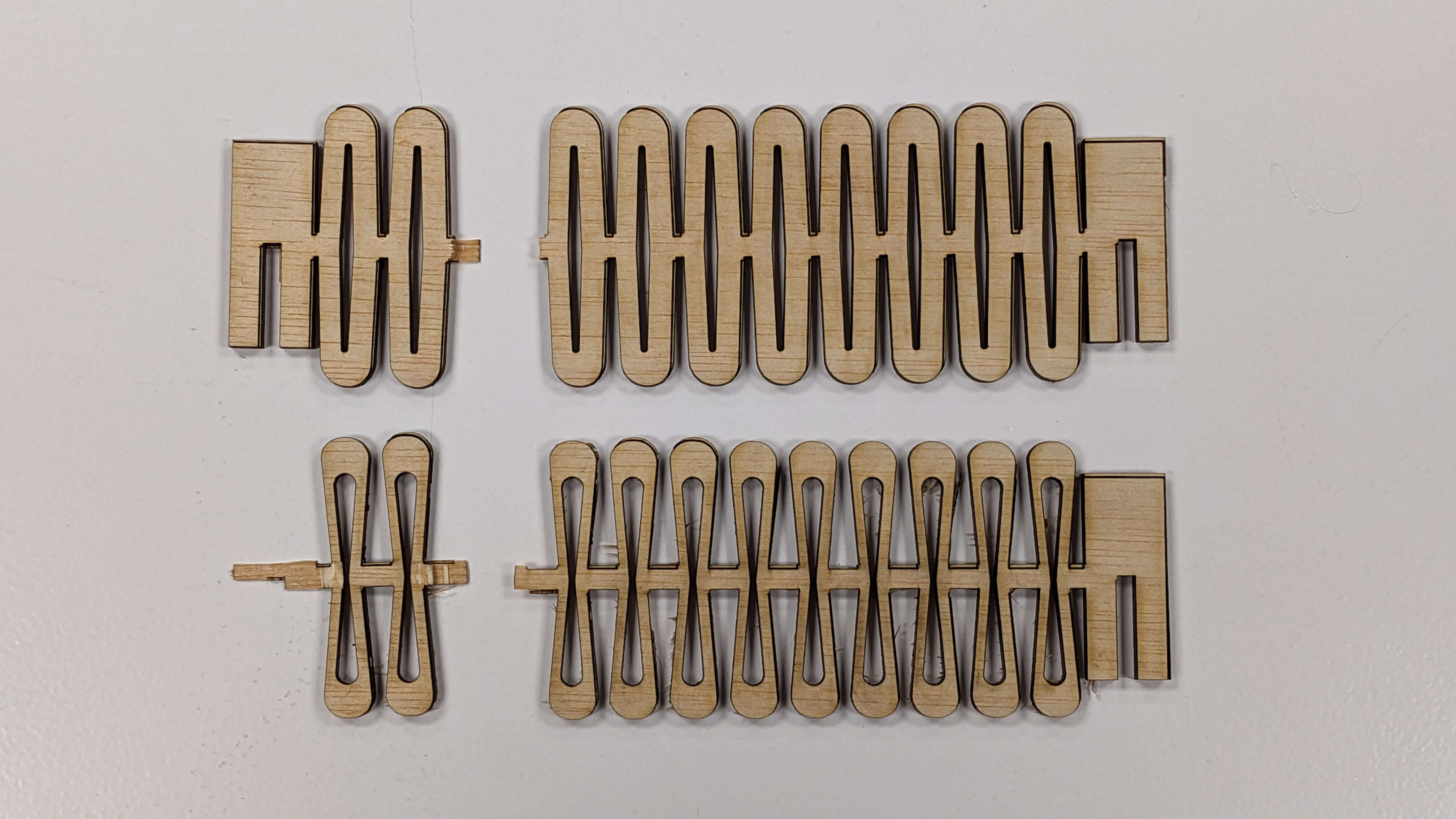
5 Divisions
These living hinges are made of 5 divisions and 3 different thicknesses of the ribs( top 0.5mm, middle 1.0mm, bottom 1.5mm). These patterns were also fragile and ended it up breaking in the process of the bending test. The 0.5mm pattern looks less broken but some of the parts came off as I was taking it out after laser cutting, so I assume it is also very fragile. I was surprised that these patterns are most fragile even though they have more connecting points than 2 division patterns.
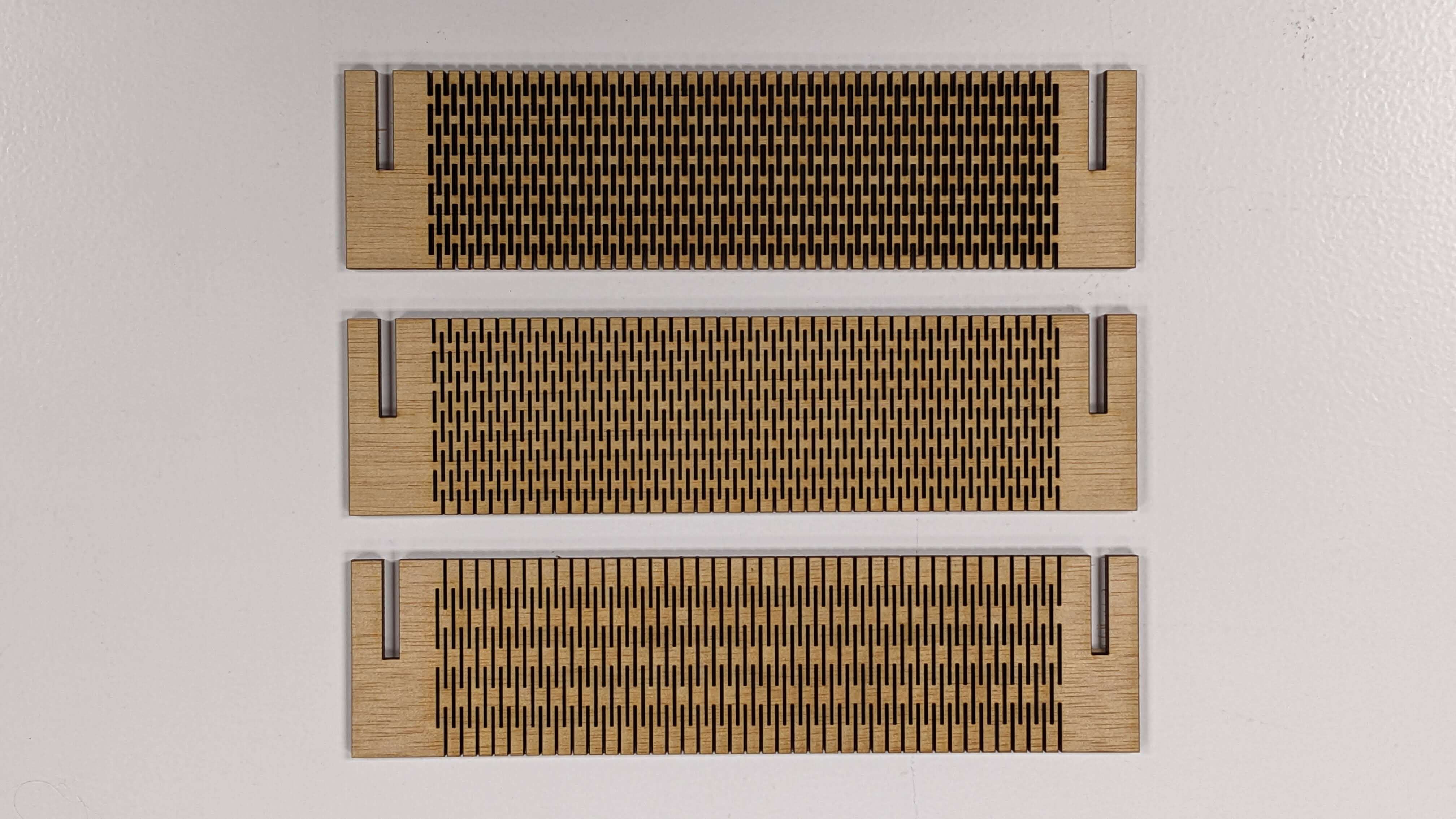
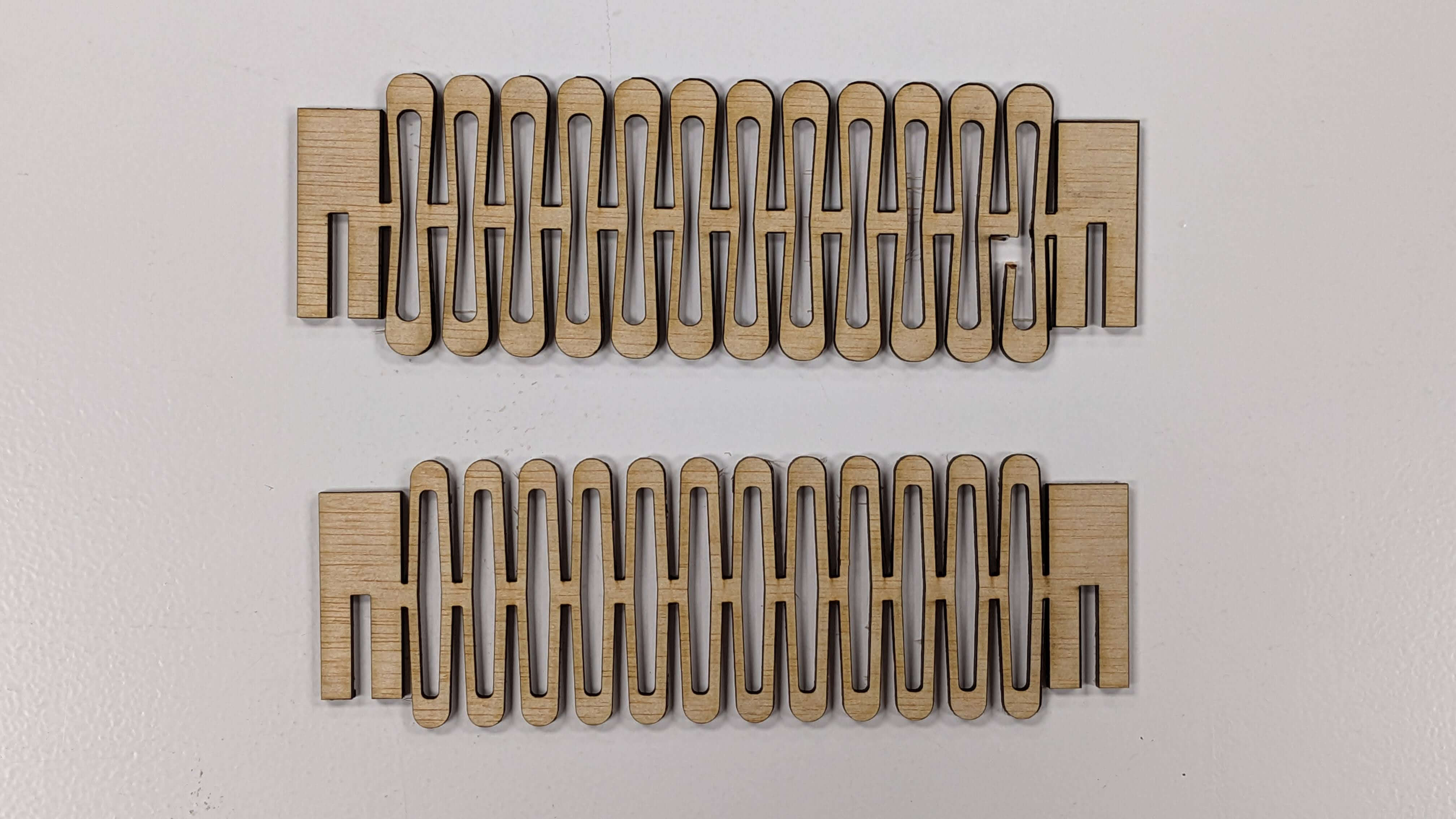
10 Divisions
These living hinges are made of 10 divisions and 3 different thicknesses of the ribs( top 0.5mm, middle 1.0mm, bottom 1.5mm). This pattern was the strongest above other patterns. It is understandable because it has more connecting points than other patterns, however, given the fact that 5 divisions were more fragile than 2division, I think it is not only about the number of connecting points. I am guessing it is a matter of finding right the number of divisions that are strong enough to connect esch ribs and at the same time flexible enough to parry pressure.
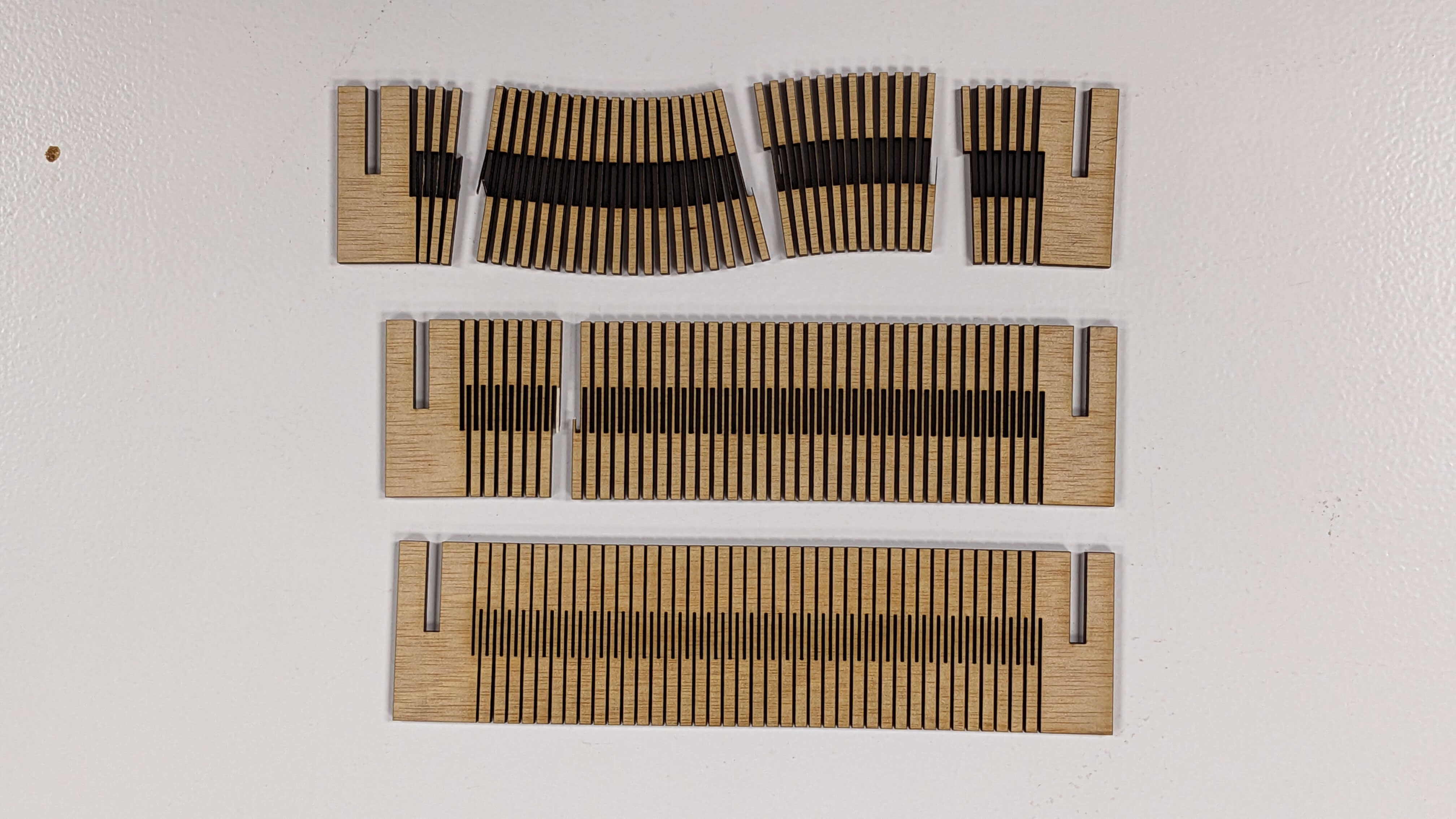
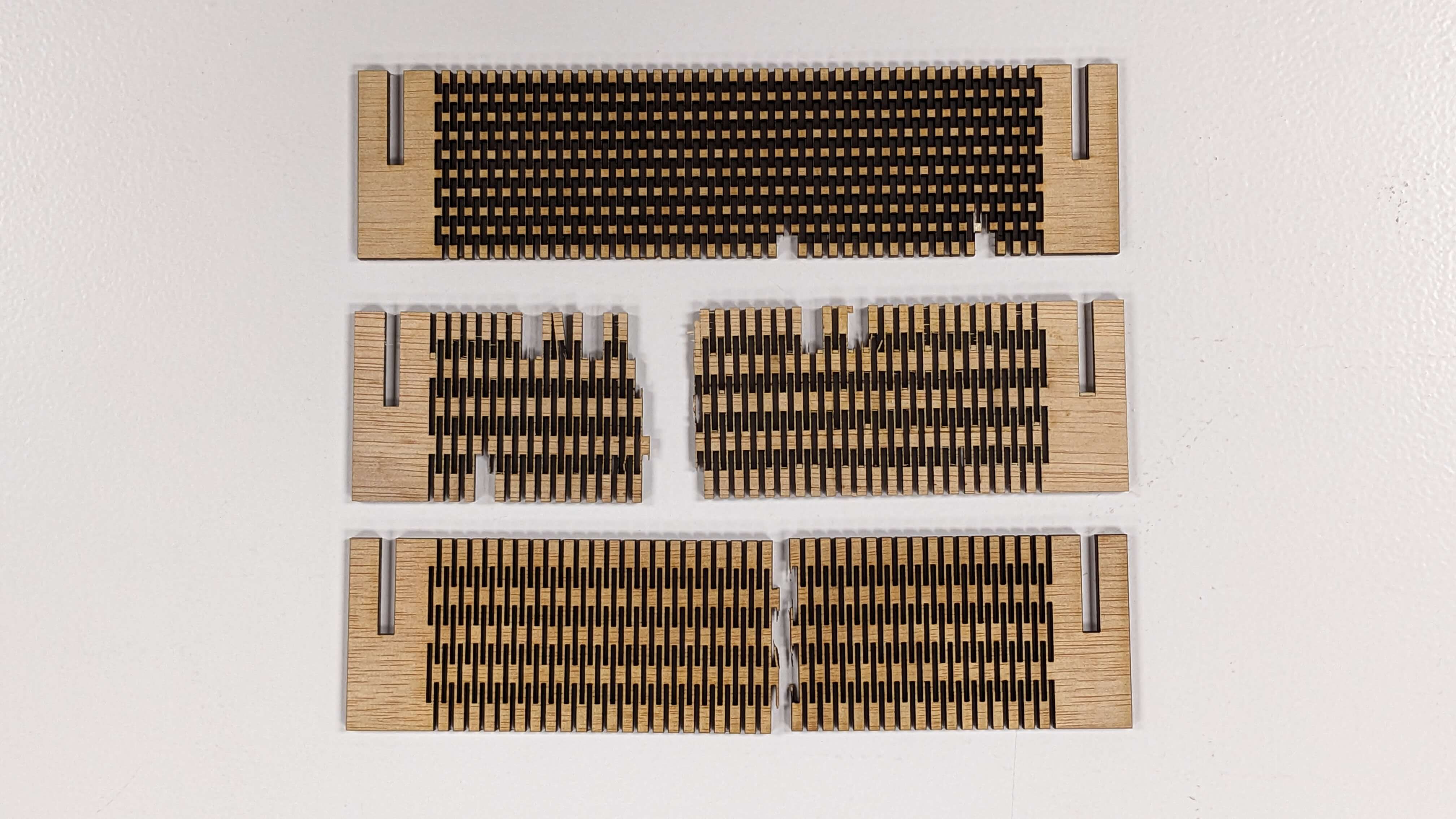
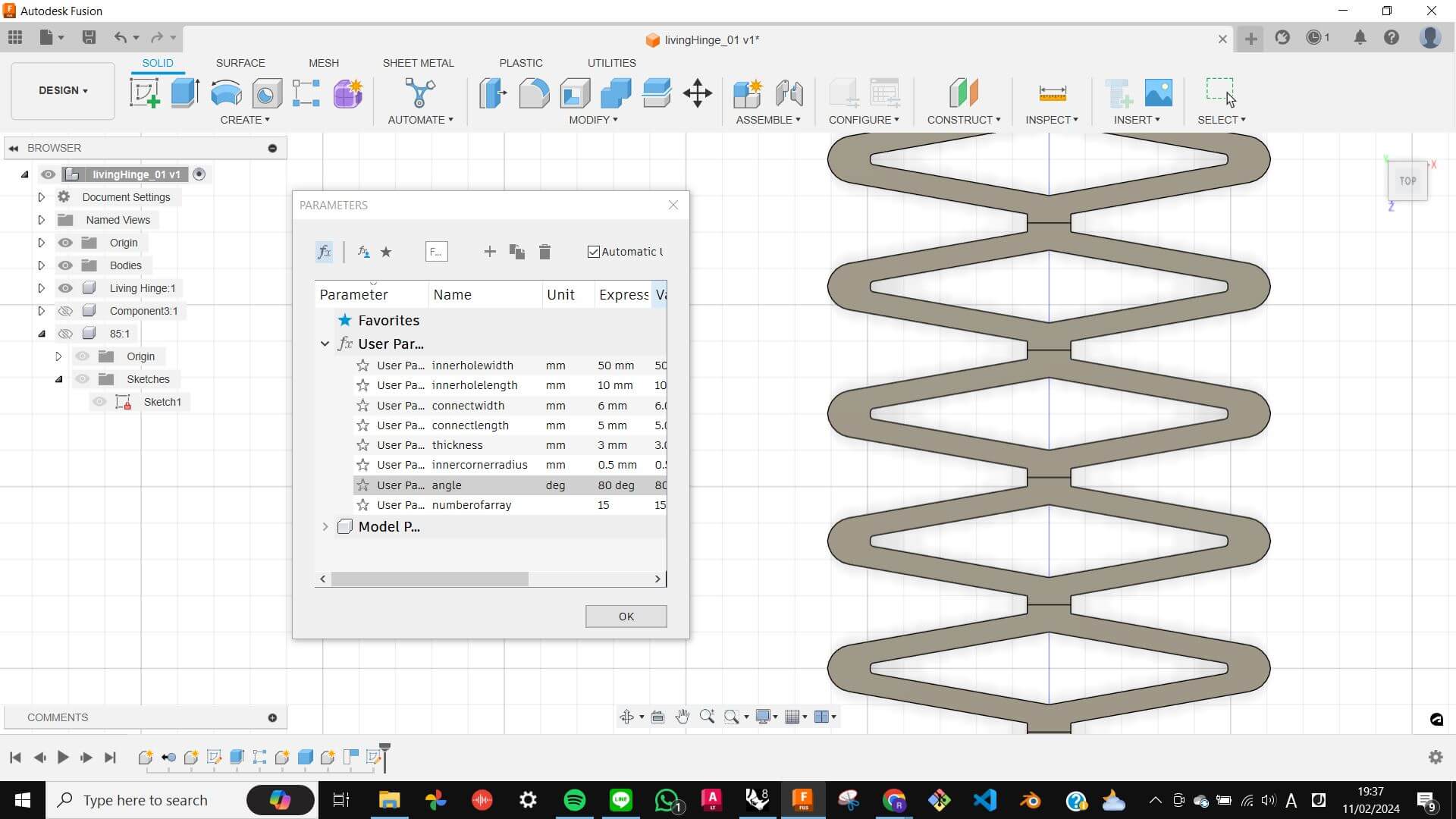
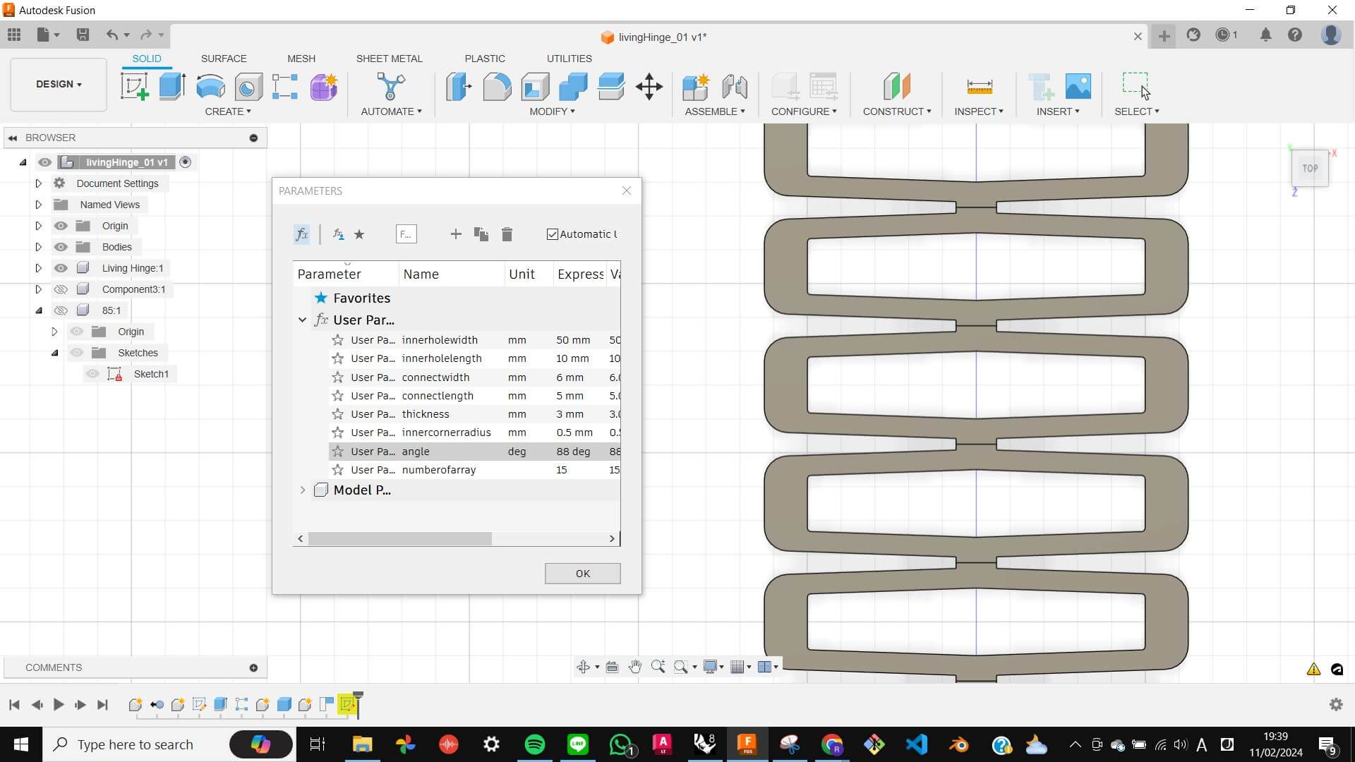
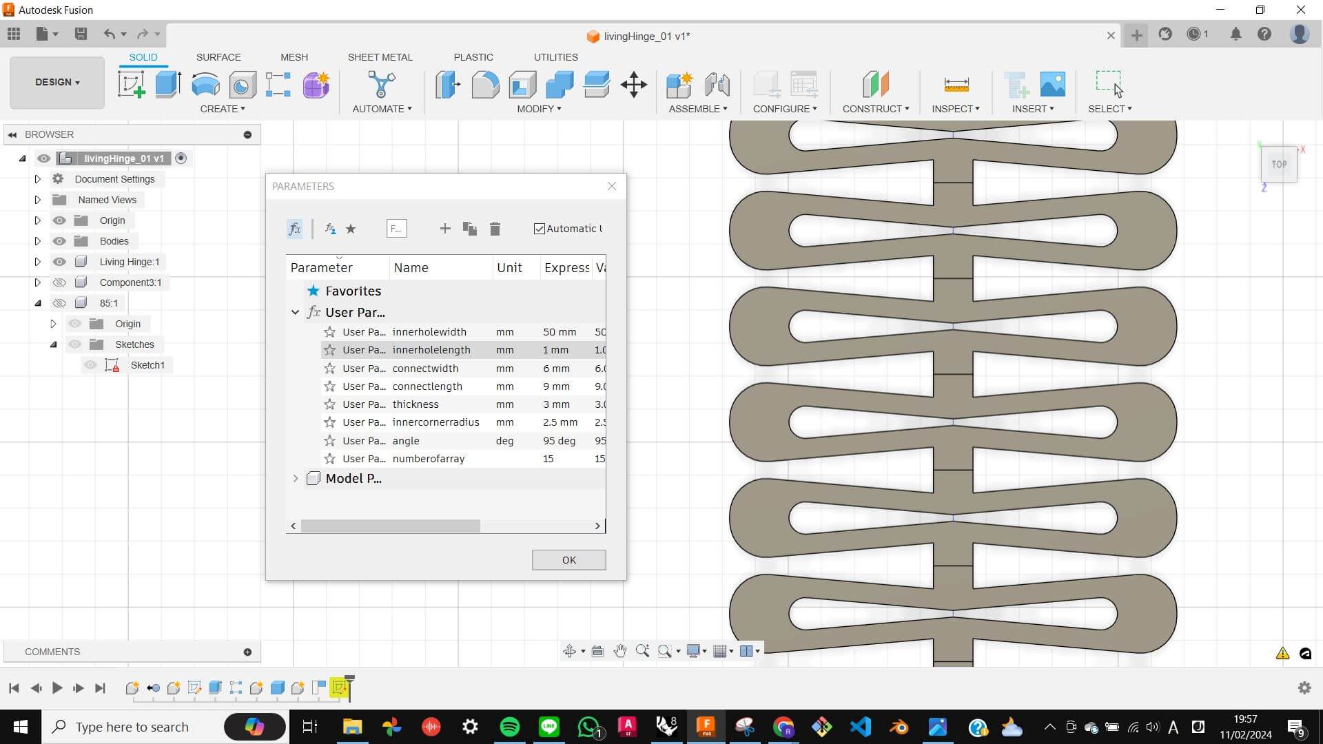
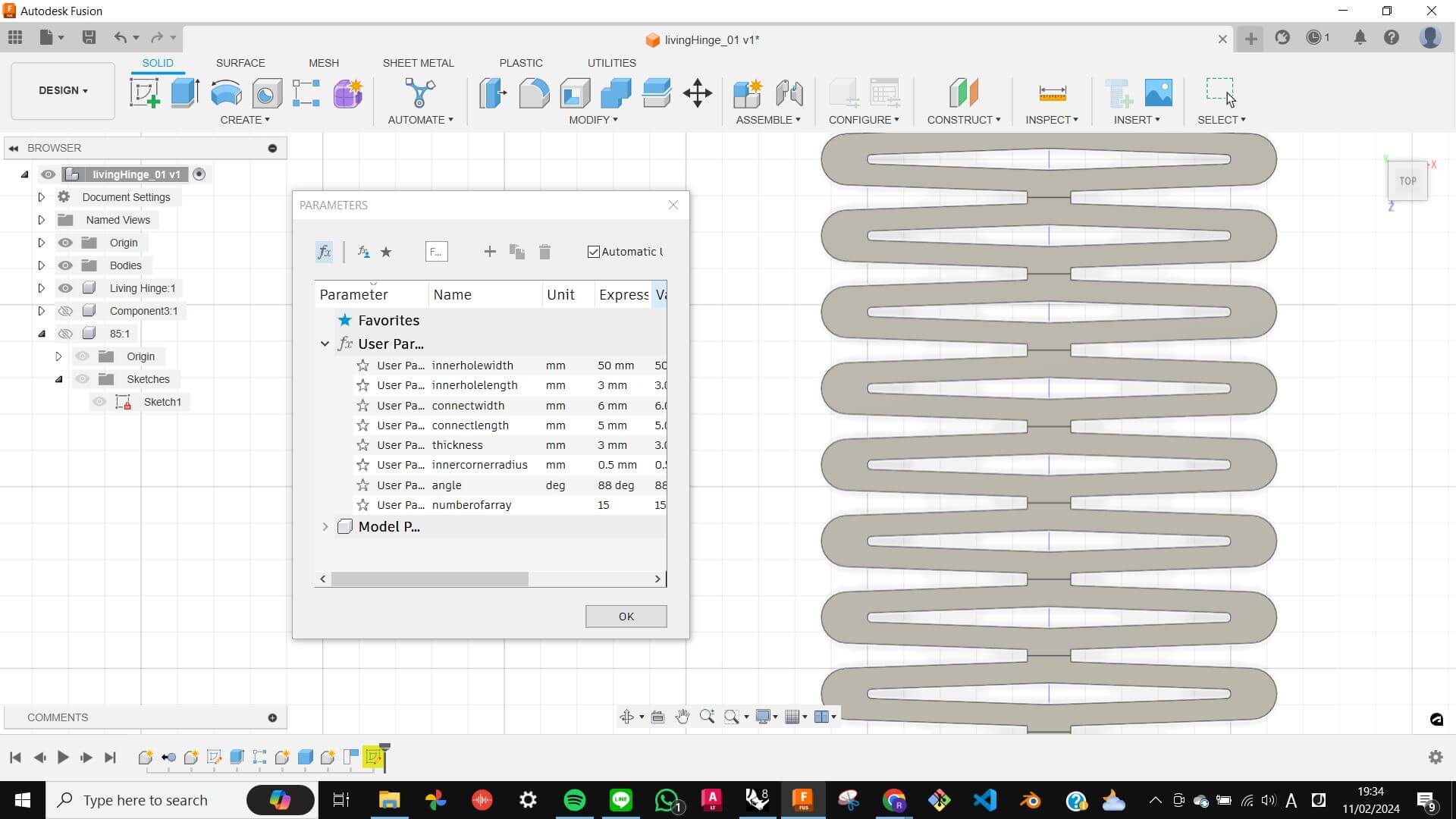
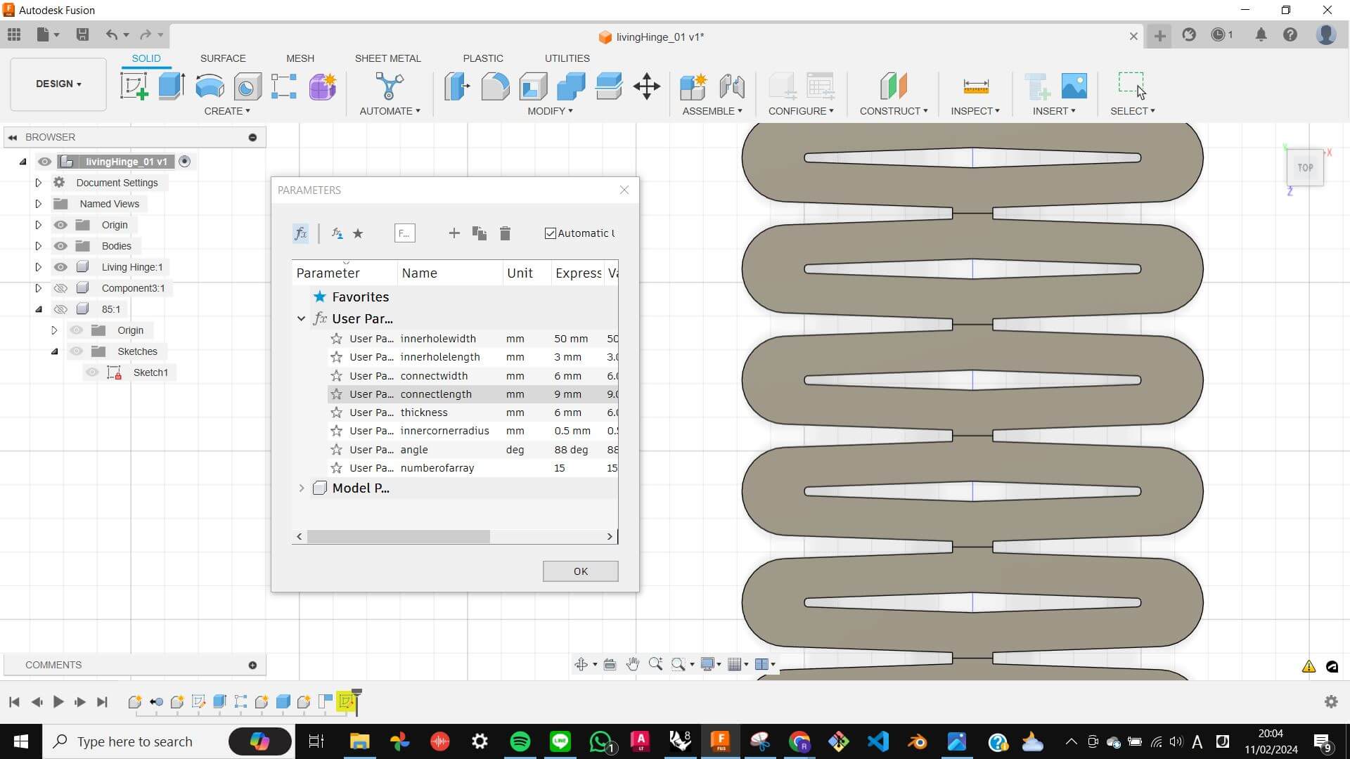
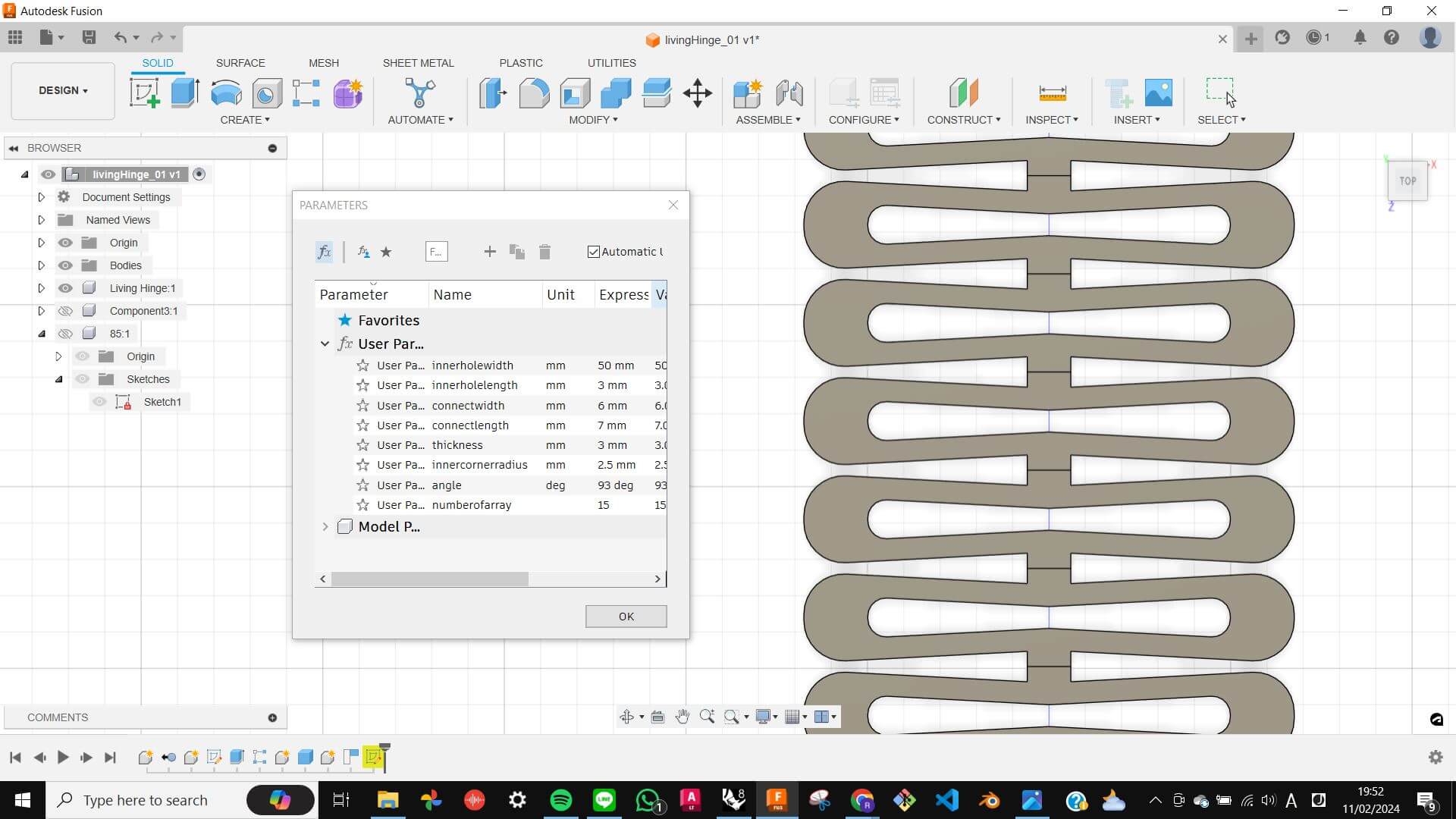
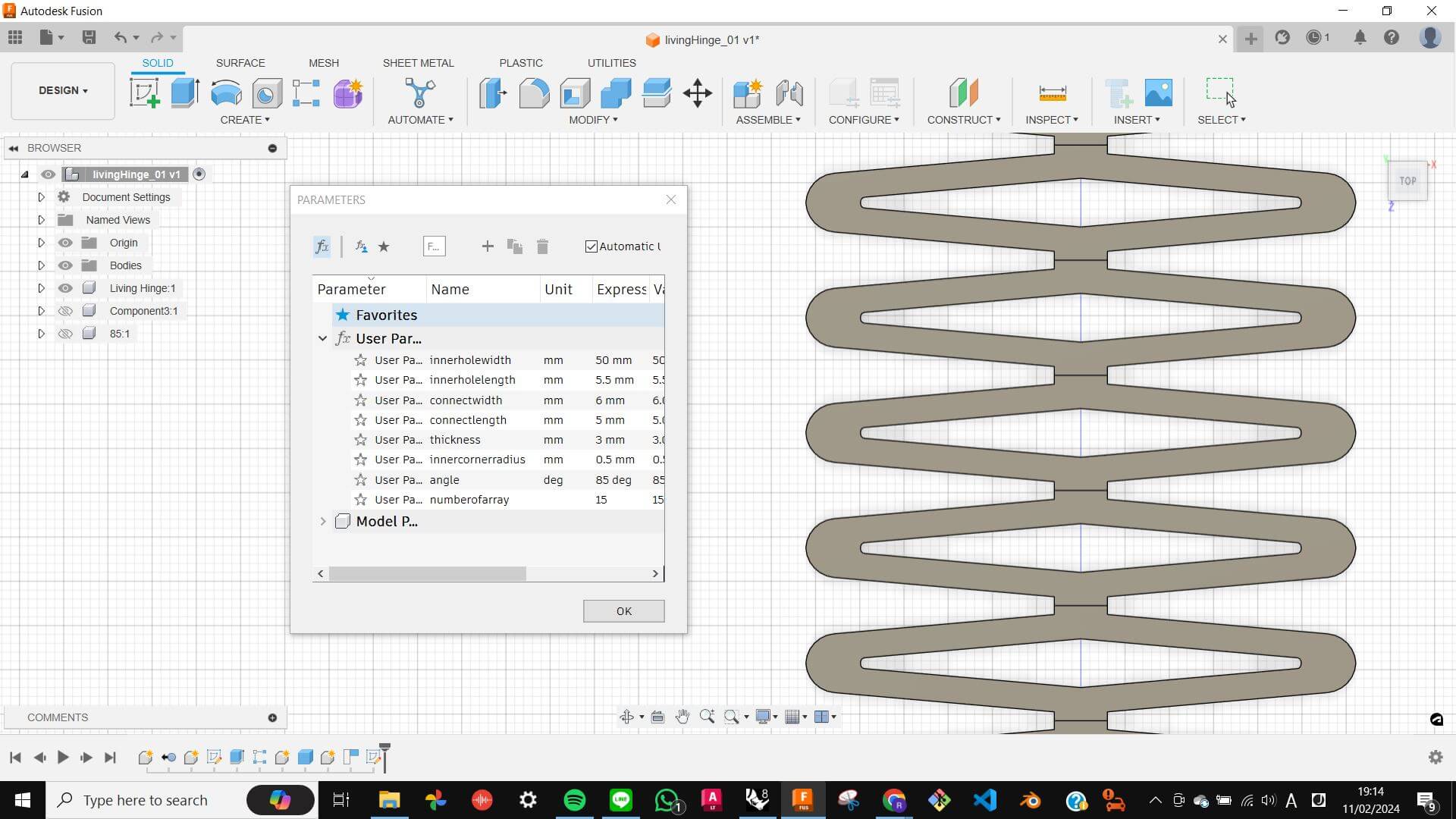
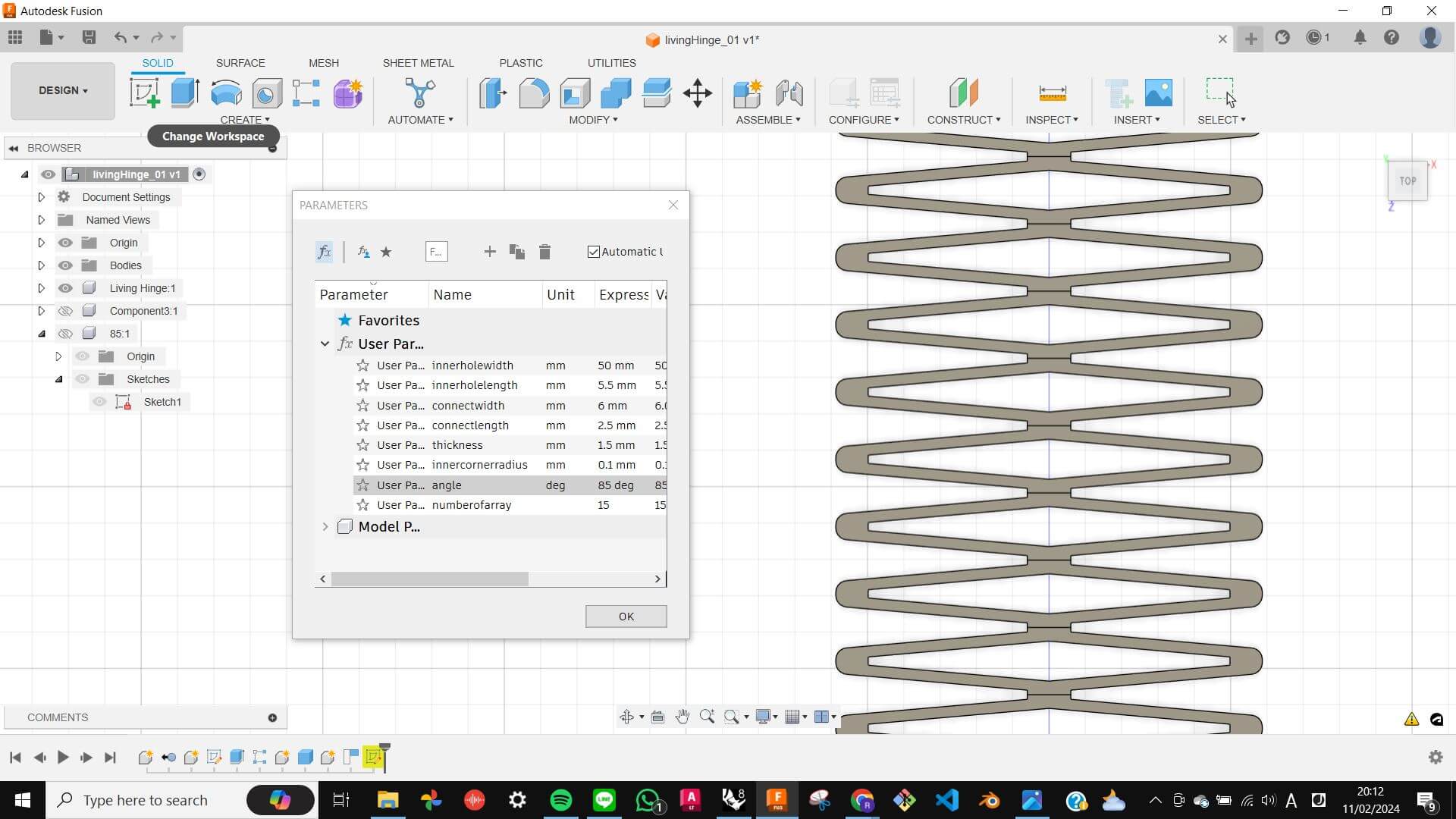
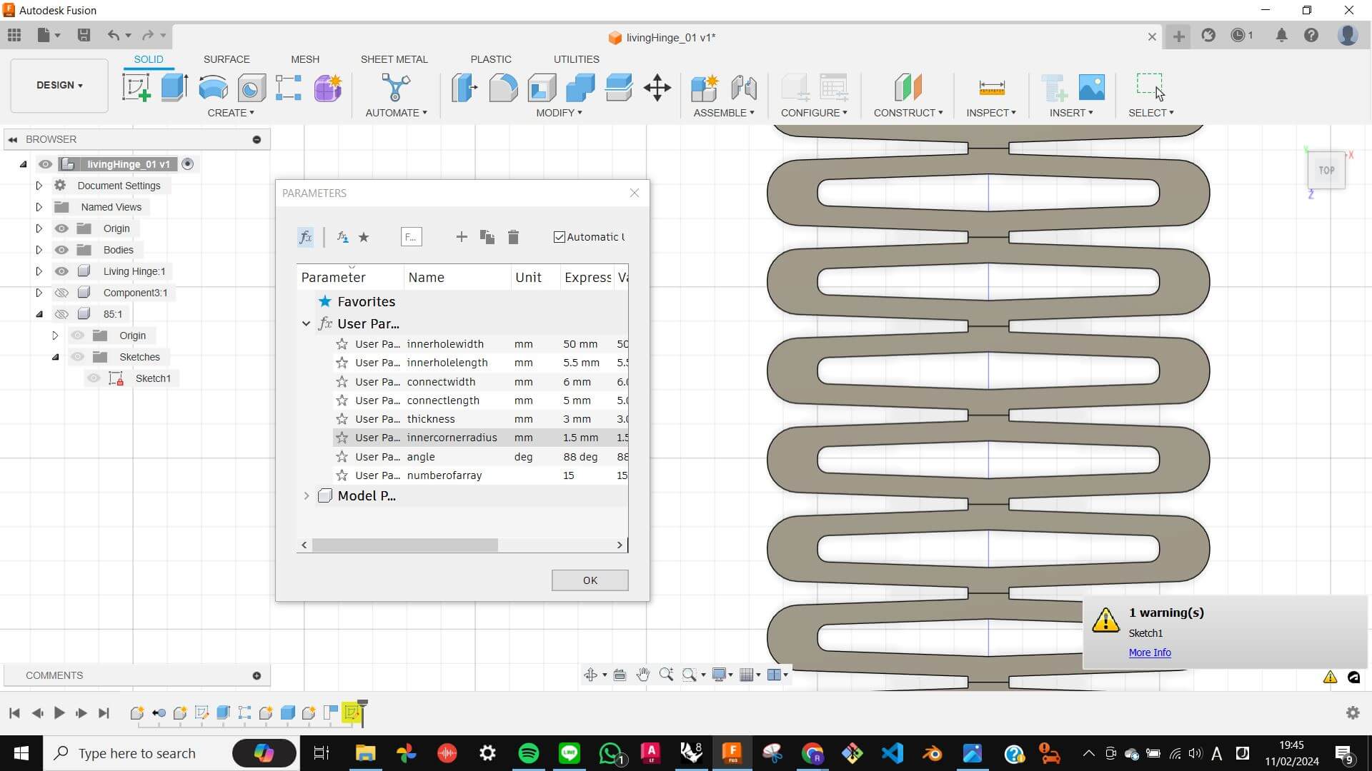
Living Hinge with angle
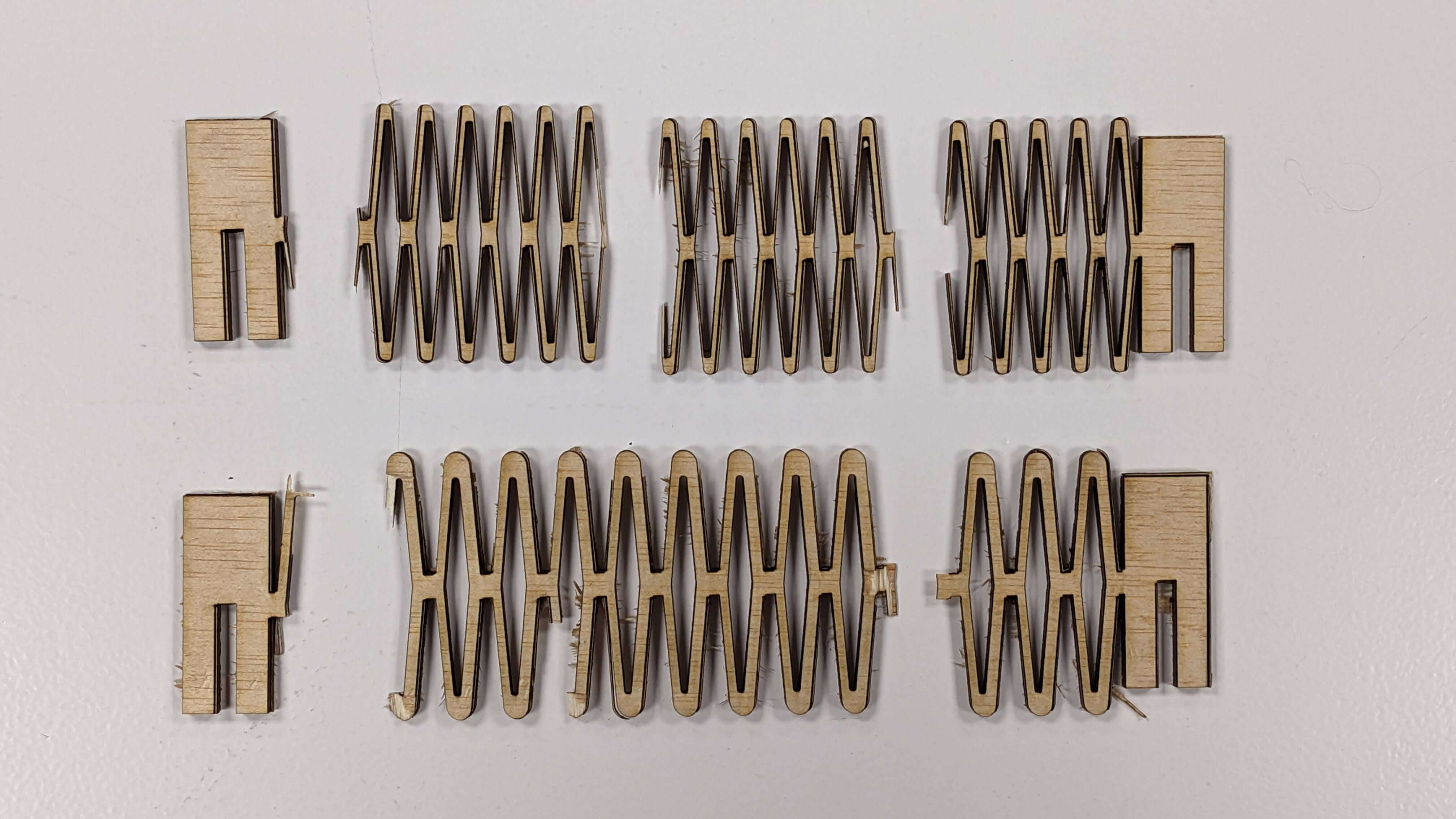
Next, I wanted to make a living hinge with angled ribs. I made 9 different patterns for angled rib hinges with parametric in Fusion 360. For the parametric making, I started with half of a rib. After constraining values, I simply mirrored and arrayed the model.
Files
02_LivingHinge_Angle_CUT_all.3dm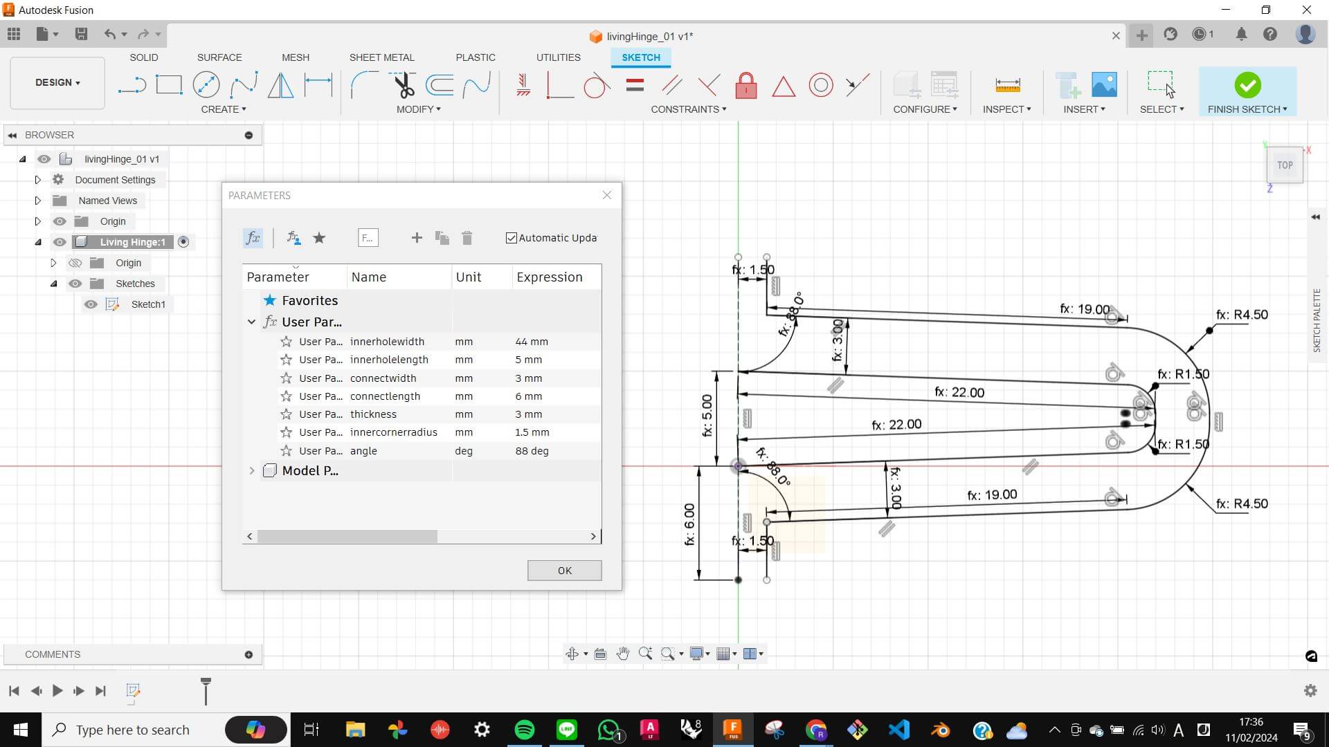
Unfortunately, all of them were not entirely cut out during the laser cut process, so I needed to cut by hand on the upset side, which caused the breaking of some of these hinges.
Overall, all of them were flexible in one direction, and some of them were also flexible in a side way. This was archived due to the angles and rounded corners giving more space for the ribs to flex. However, those hinges that have more angled ribs tend to break easily.
By the way, I will give full credit to my tutor Snati for successfully breaking one of my living hinges.
Rail for bending
As an extra stuff, I quickly made this rail stand for measuring the degree of bending hinges. It came out as I imagined. However, If I were to make this again, I would give more space on the vertical edge of the triangle because the edge became an obstacle as the hinge bends.
Files
Rail for bending.3dm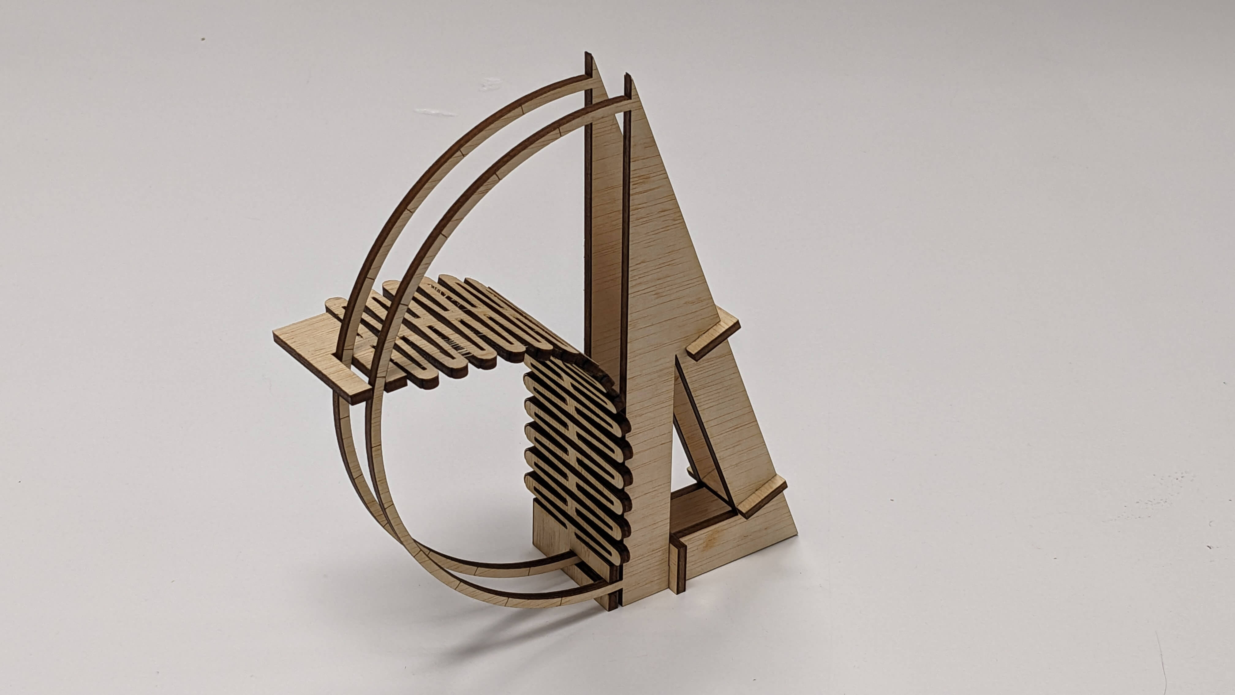
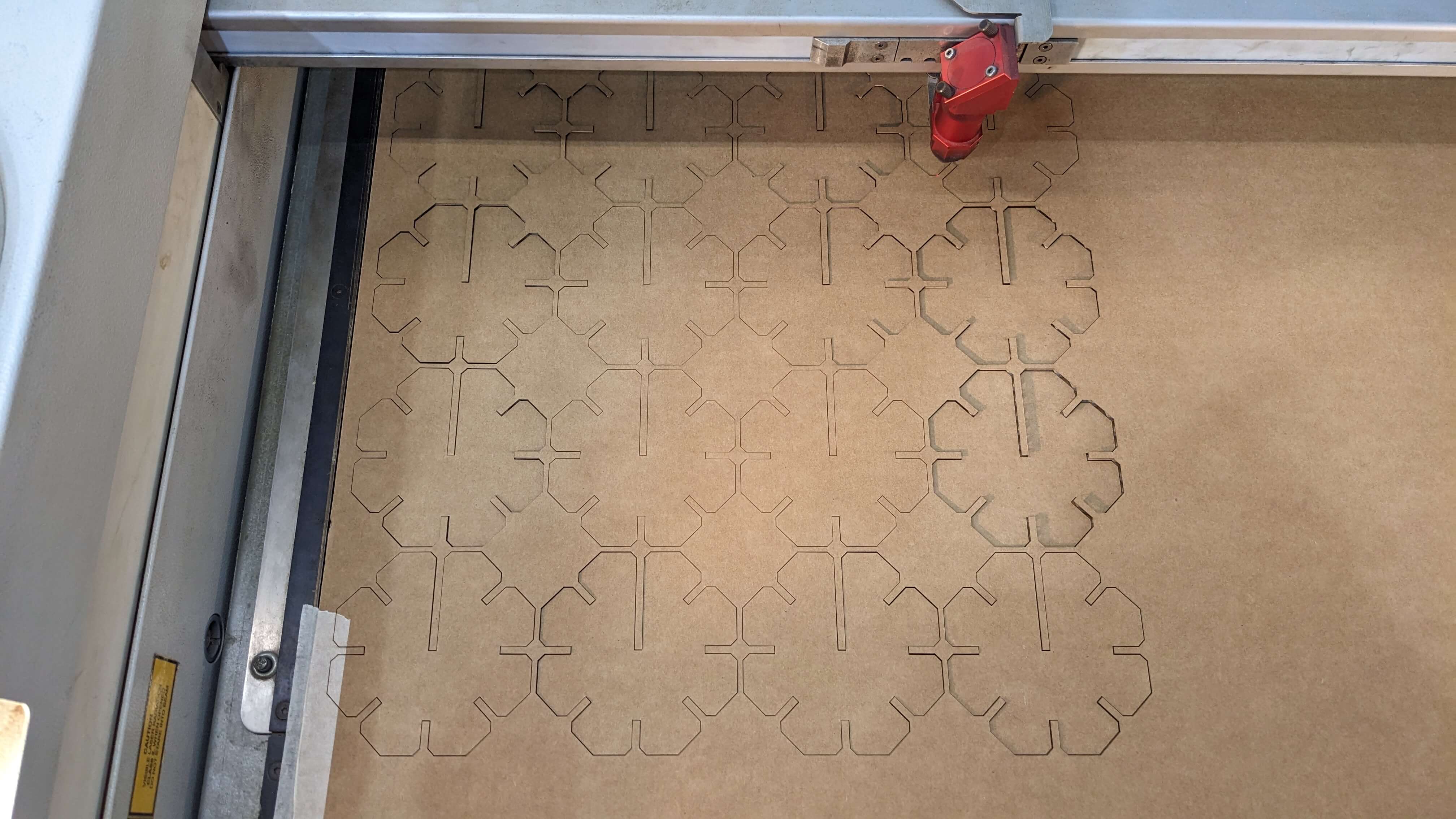
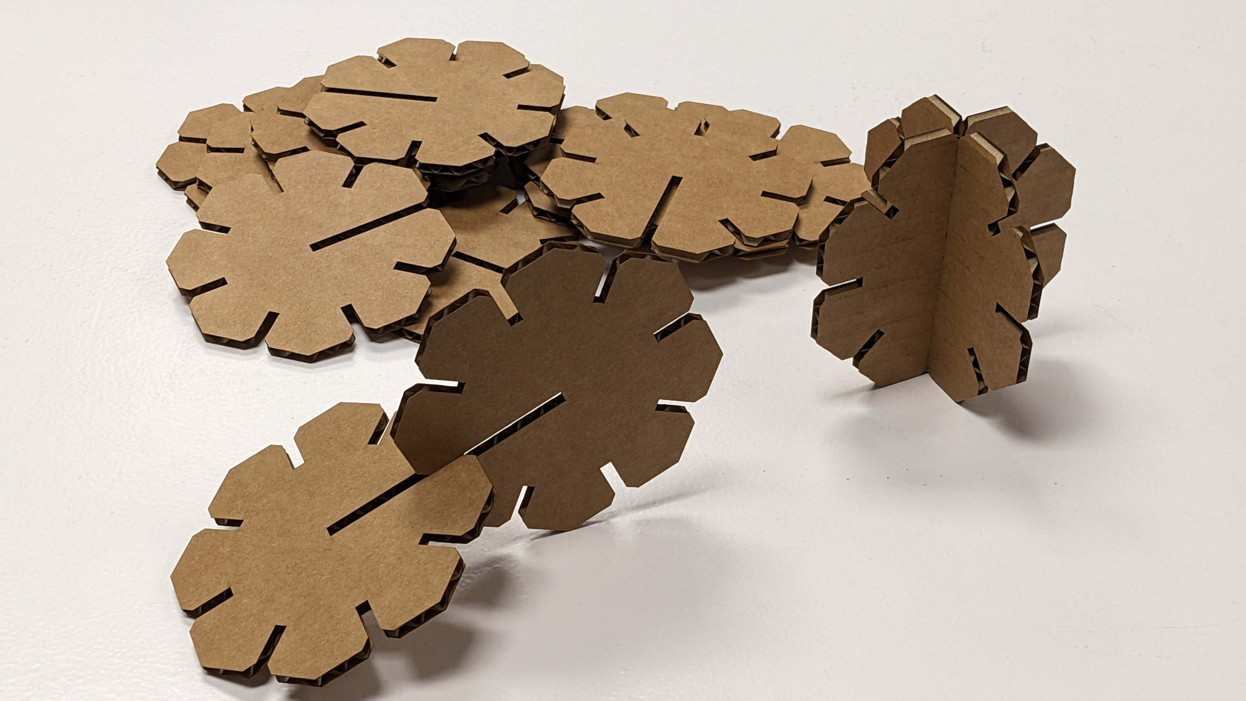
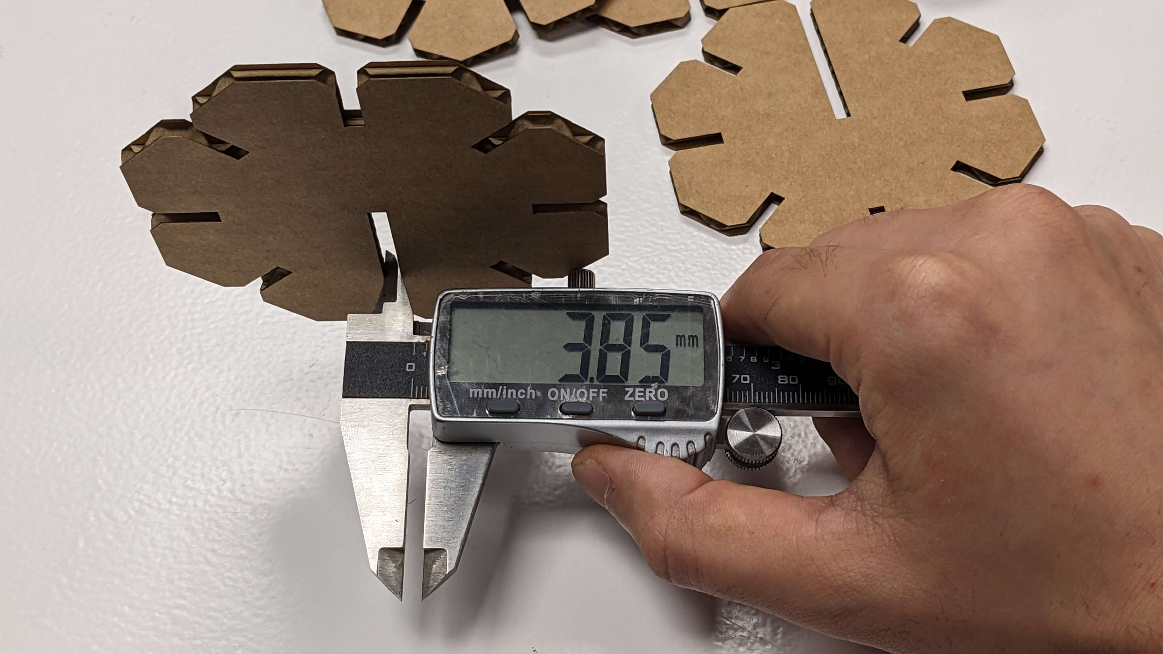
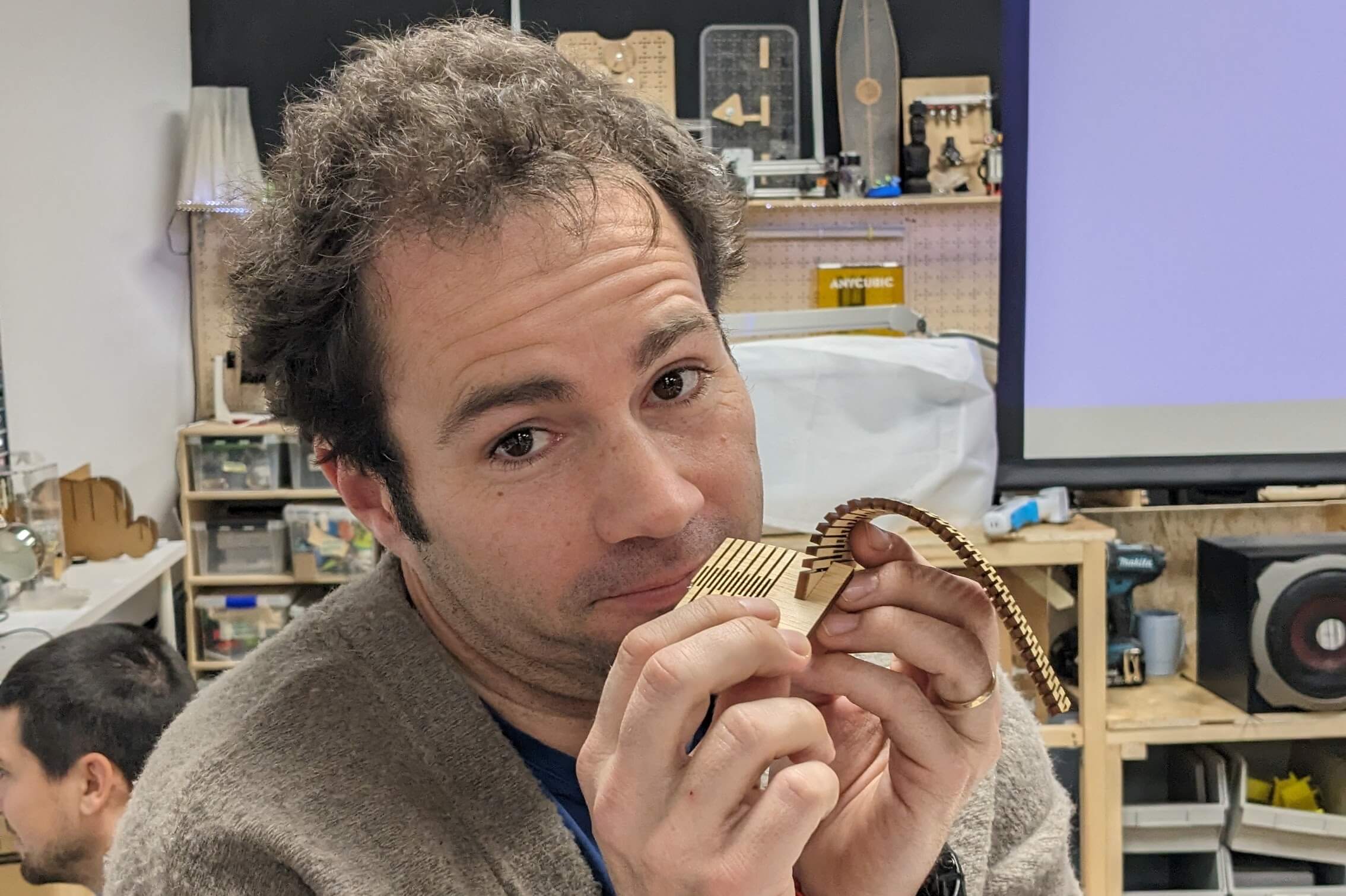
Double Curvature Surface
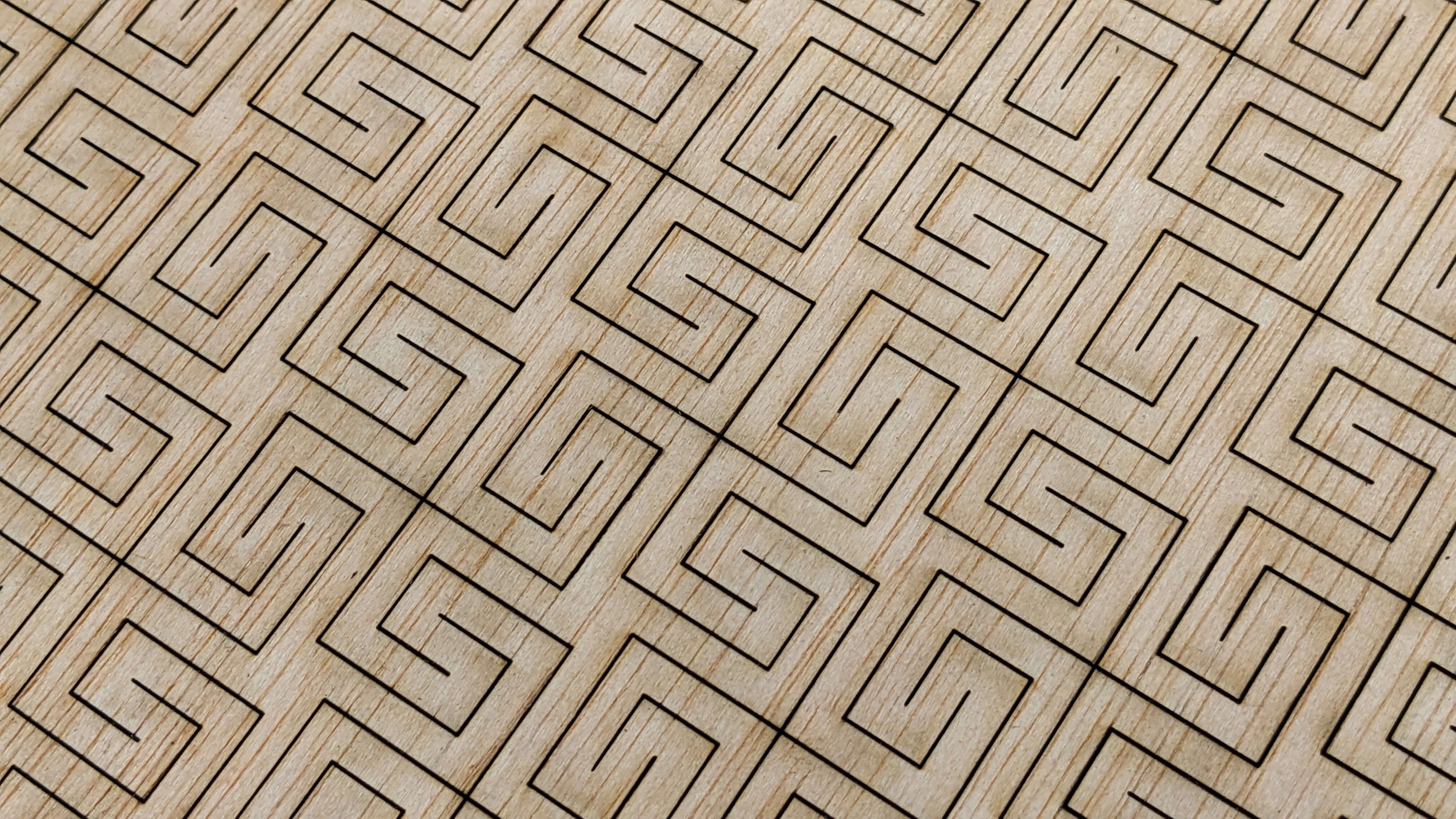
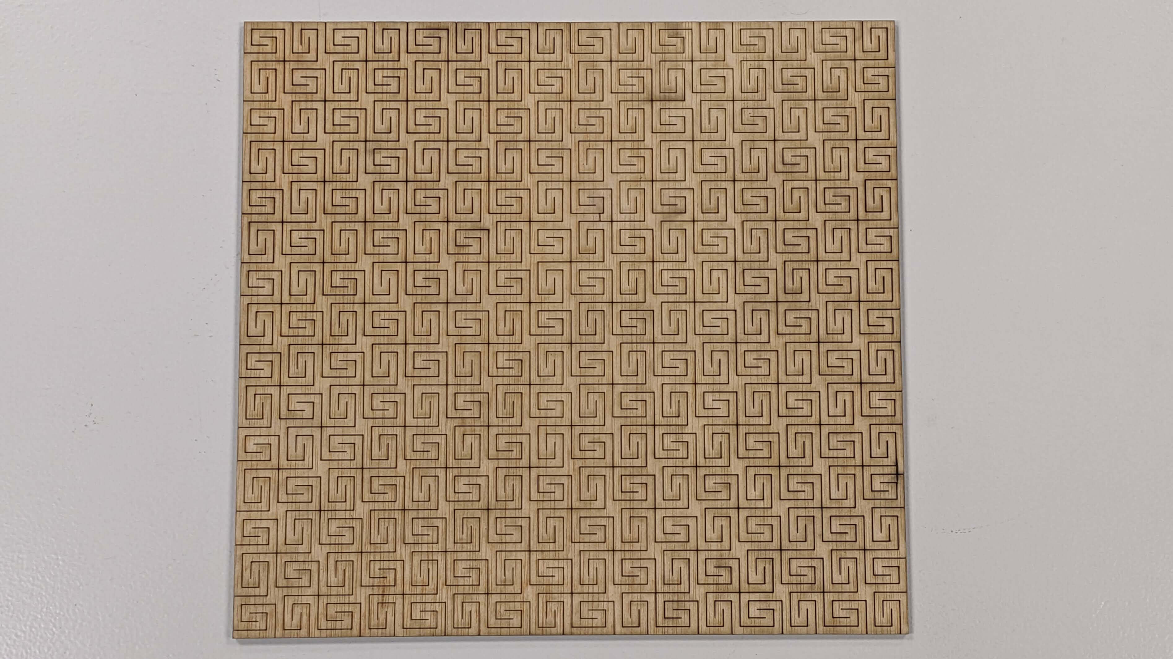
I wanted to try making Flexture because my final project will require some kind of movable surface. I simply watched the video clip of Flexture being laser cut and figured out the basic pattern. Then I modelled in Rhino in a way that suited the size I wanted to make. As I was modelling, I began to understand more about the structure of the pattern. It was very simple. It is a series of arrayed swastika-looking marks.
Files
03_Flexture_CUT.3dm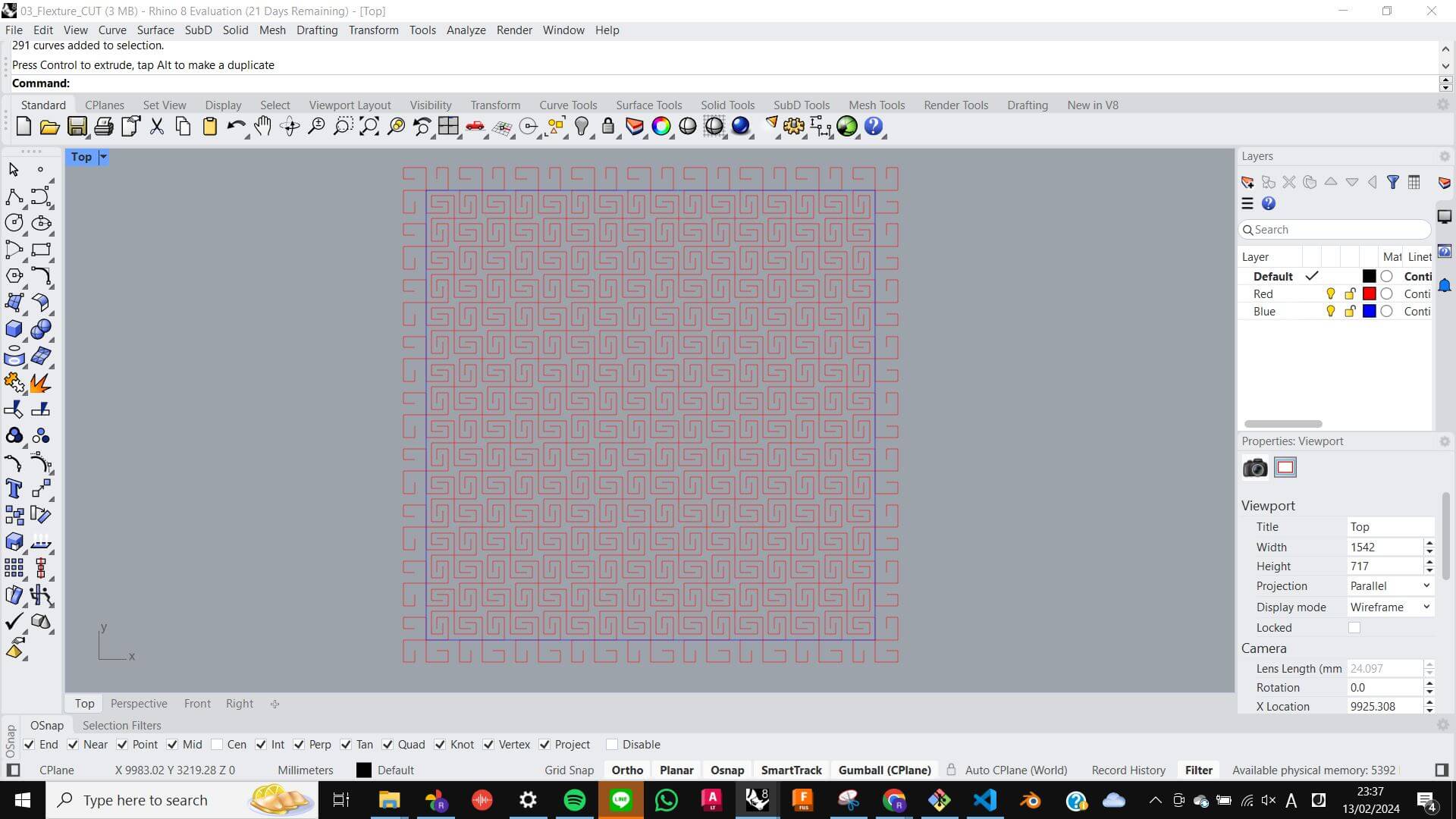
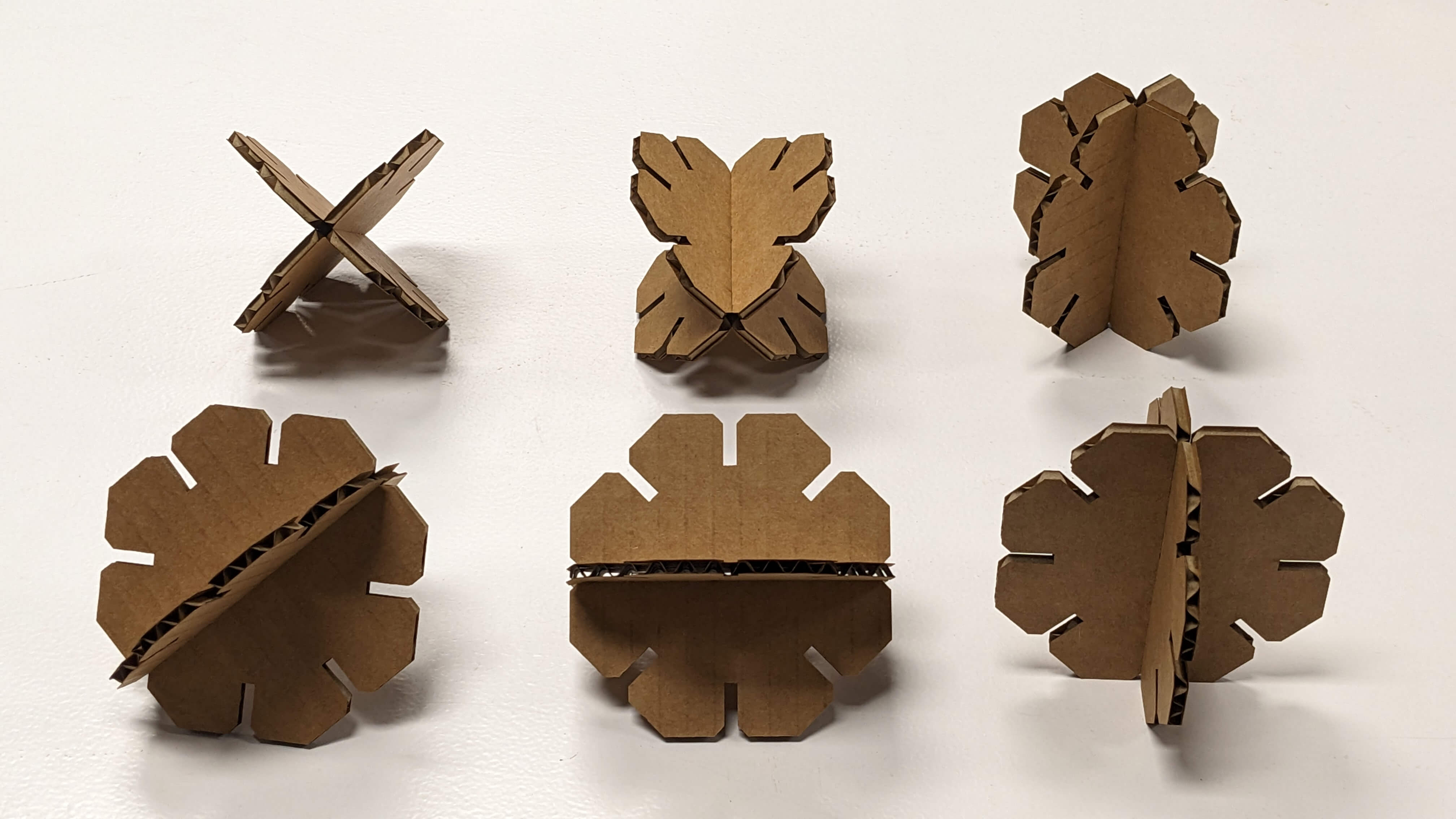
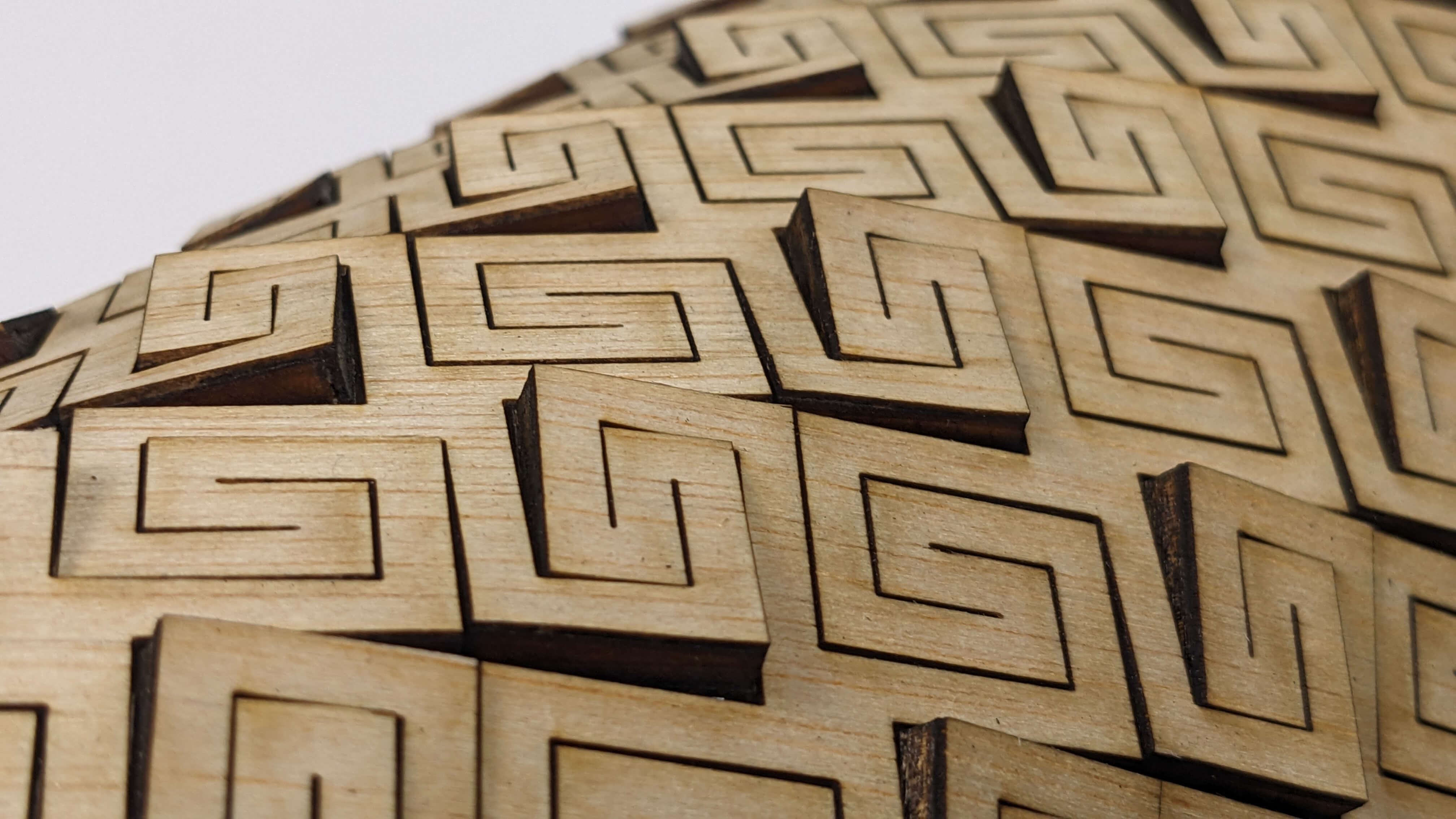
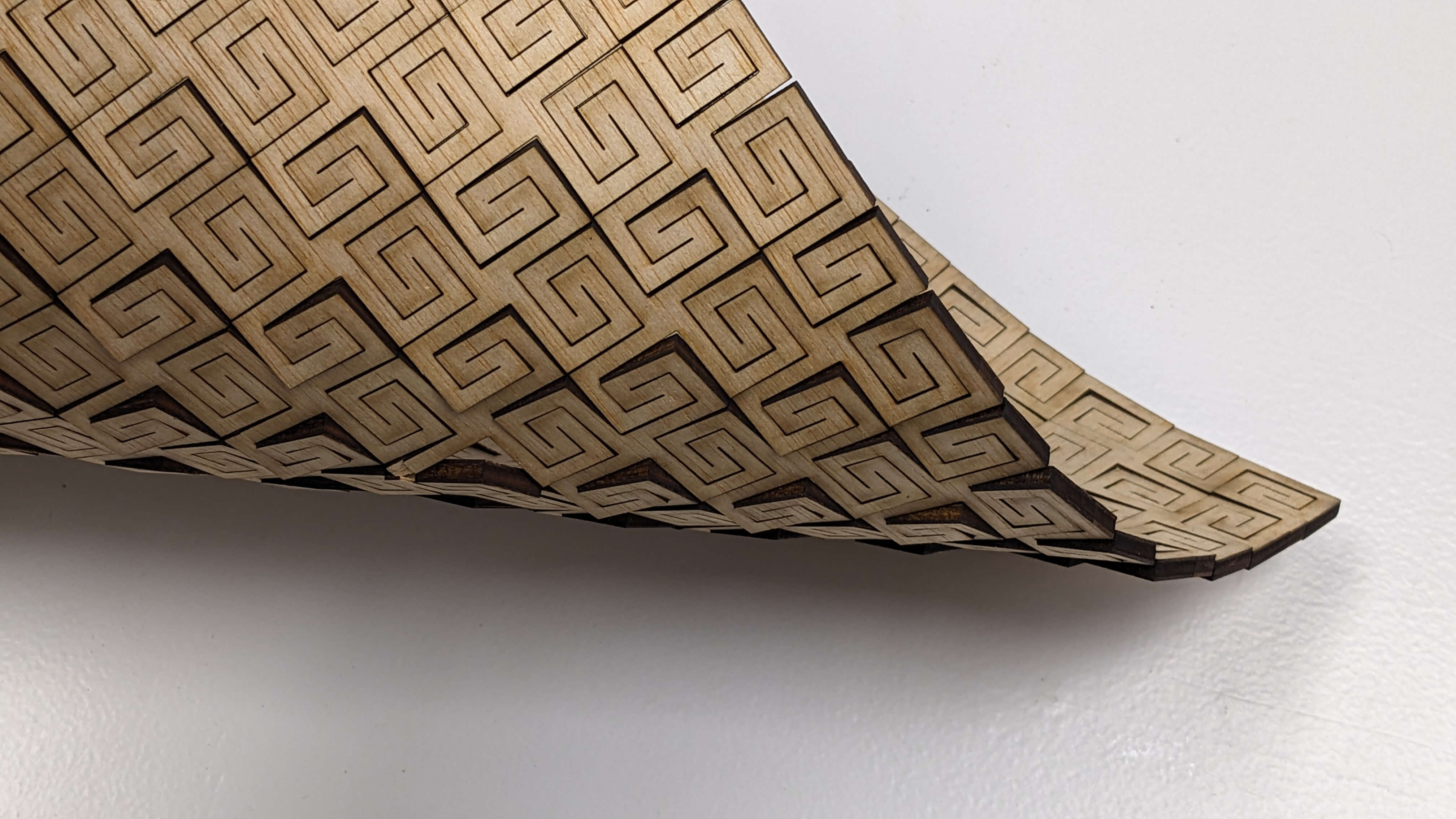
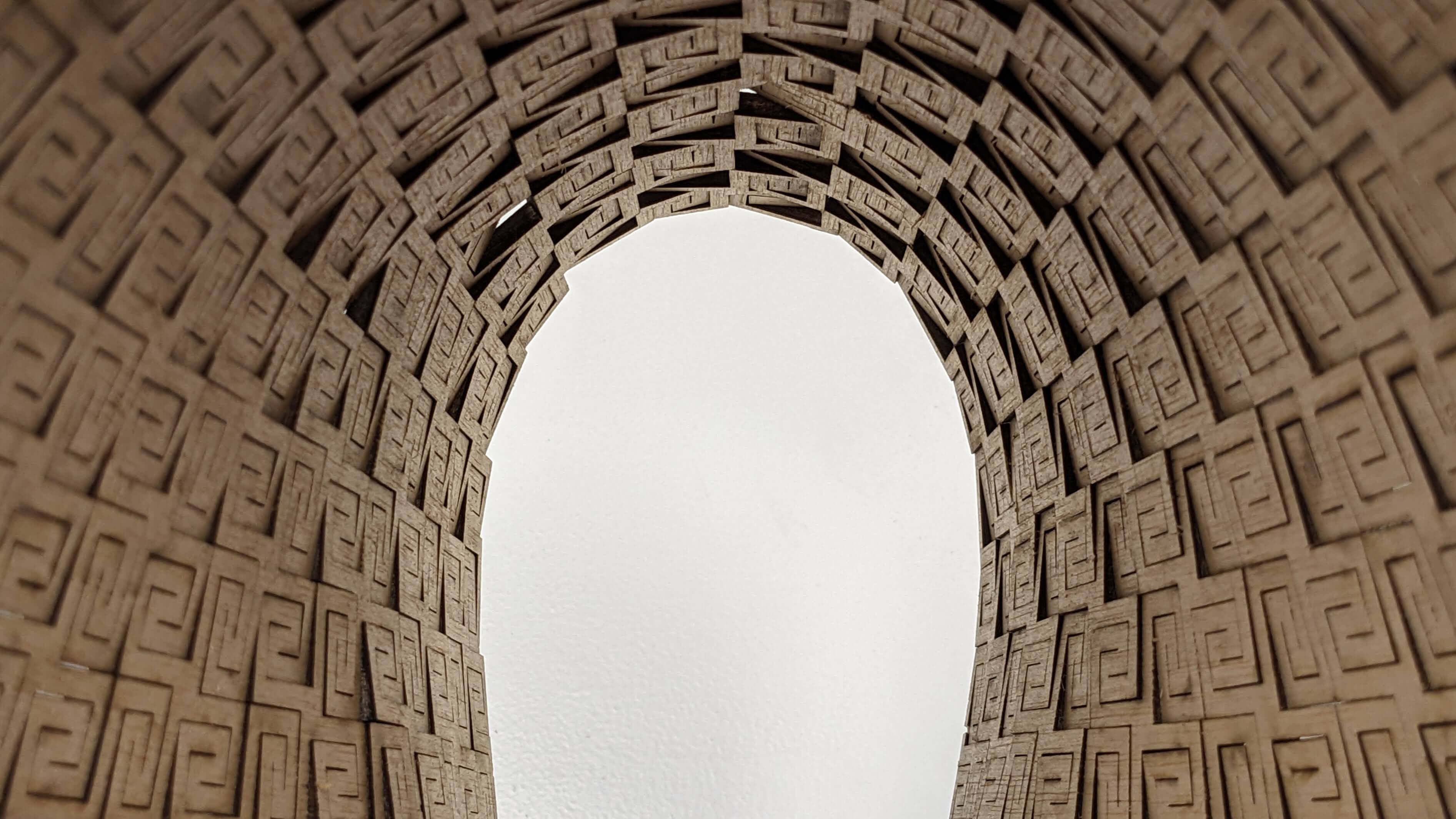
When it came out from the laser cutter, it still felt like a kind of wooden plate, however, as I bent it at a different angle it started to become more stretchy and felt something like springs. I find interesting about the texture on the surface when it is bent. Also, I found out that It looks beautiful from the bottom perspective.
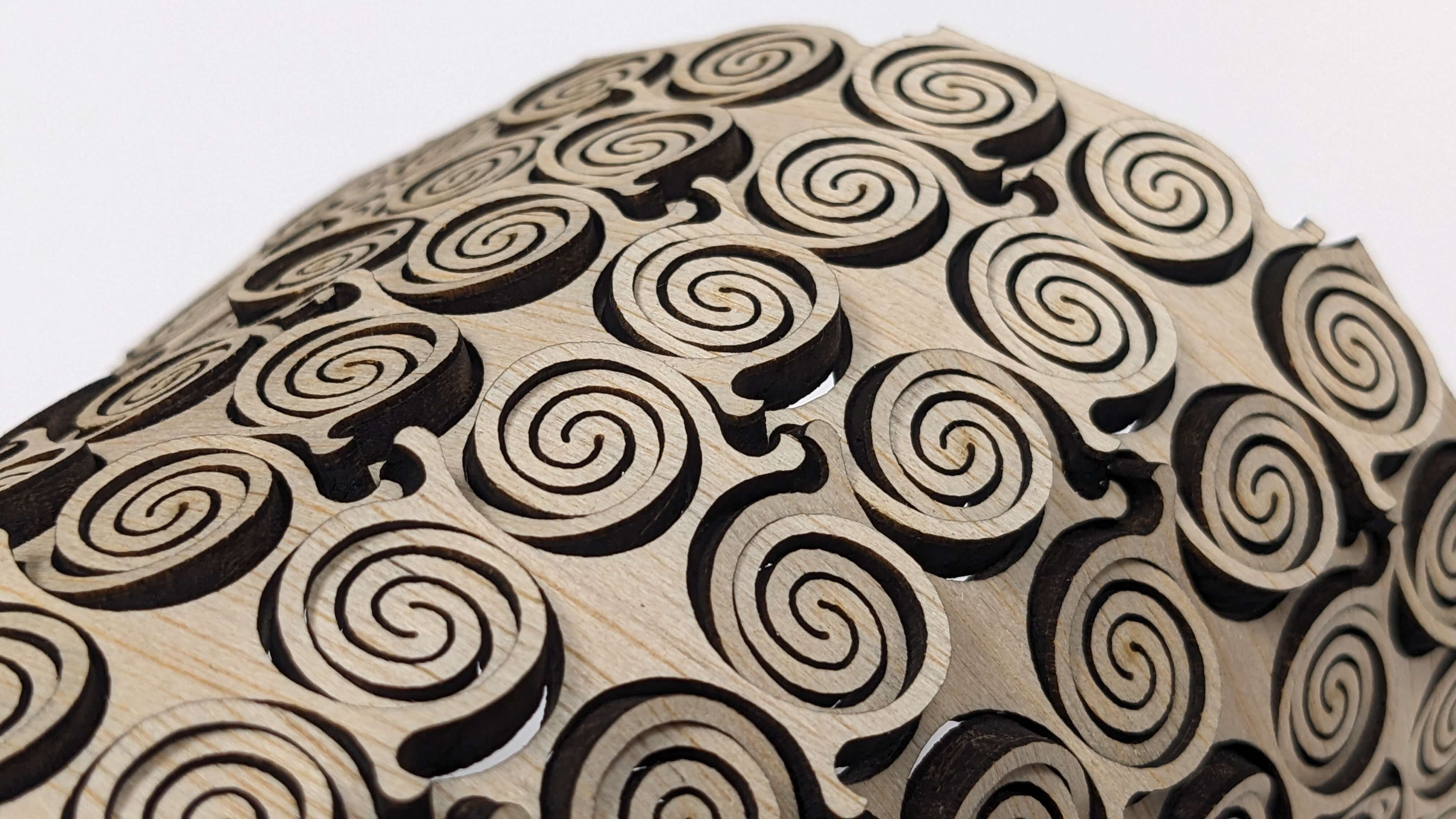
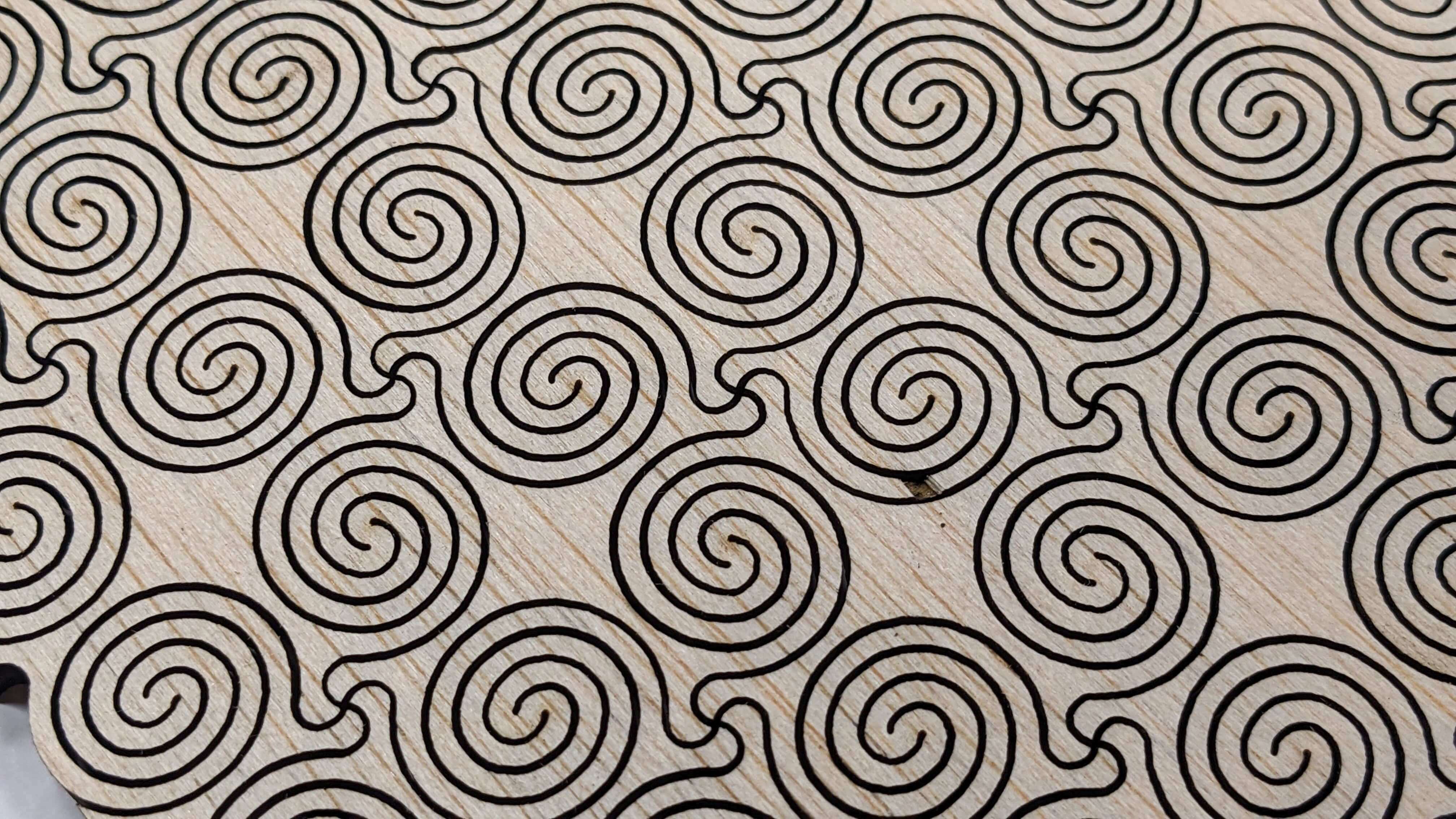
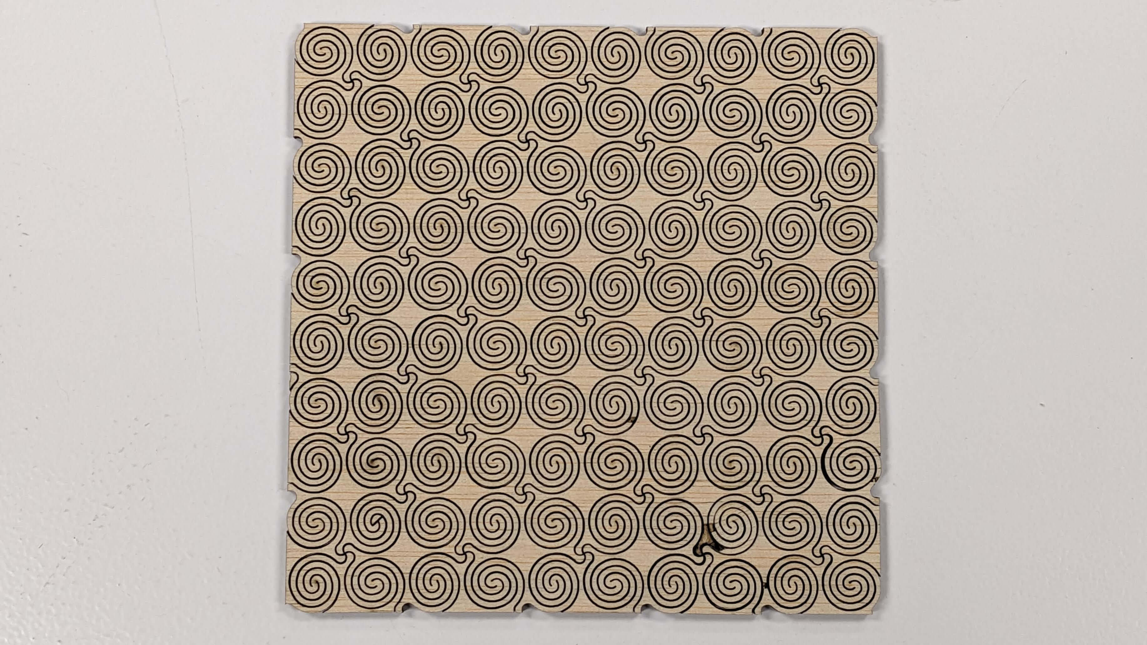
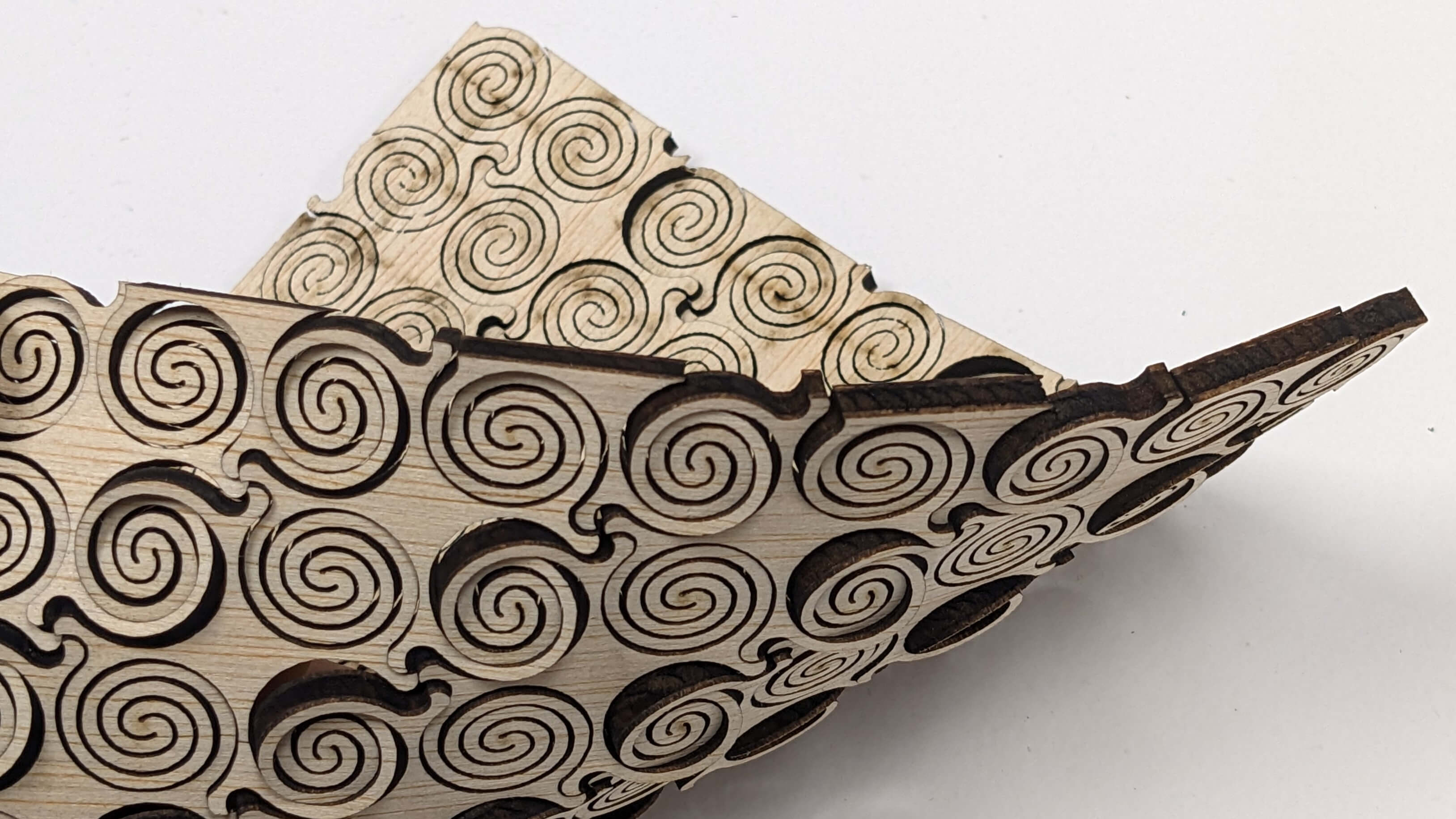
Double Curvature Surface with circle pattern
I wanted to create a circle-based pattern using the same structure as the previous Double Curvature Surface. I simply modelled in the same process as the previous one but used circles instead of squares, and then I and up this pattern.
Files
03_Flexture_CUT.3dm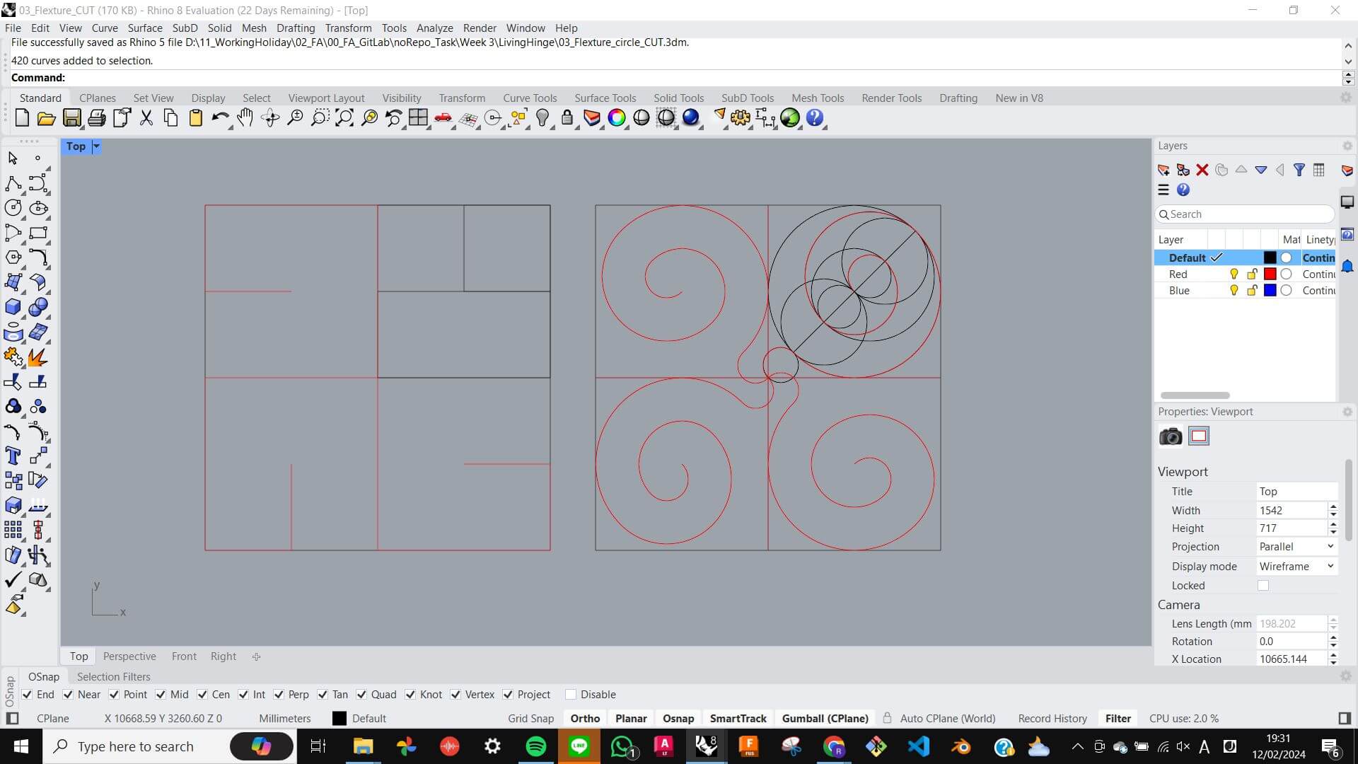
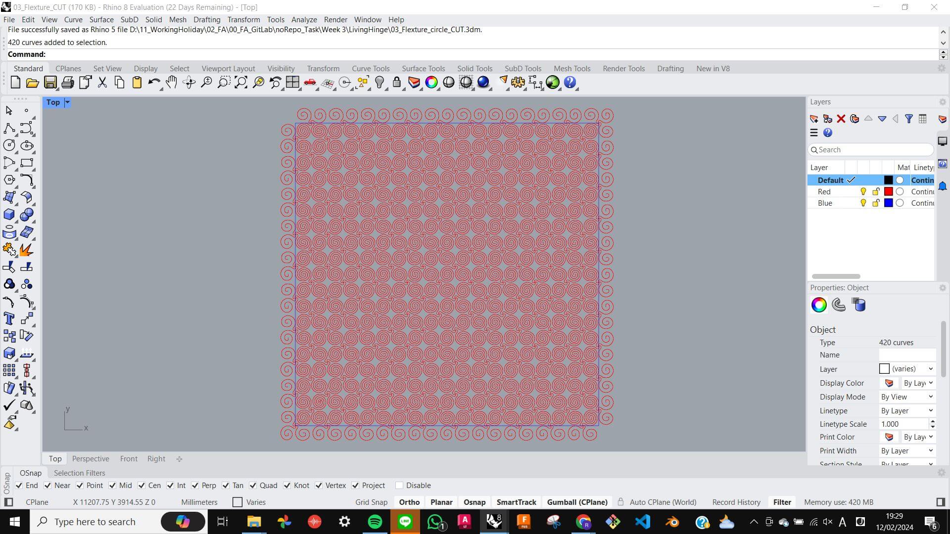
As a result, it was a beautiful pattern on the surface and also able to bend as much as the previous Double Curvature Surface, However, the ribs were a little thinner and caused it to break on some parts.
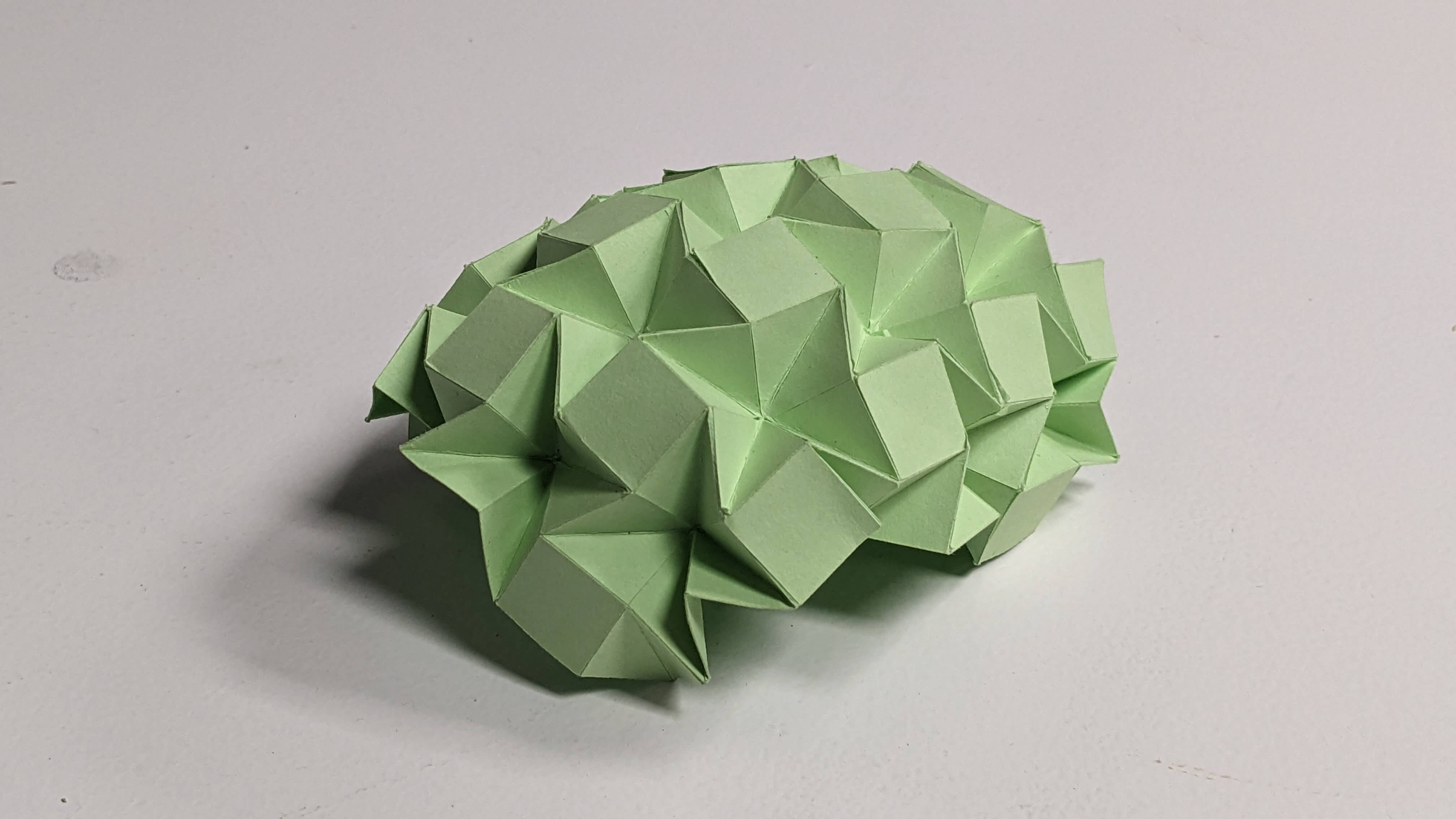
Origami
I wanted to try origami structure since it seems like something that allows movement.
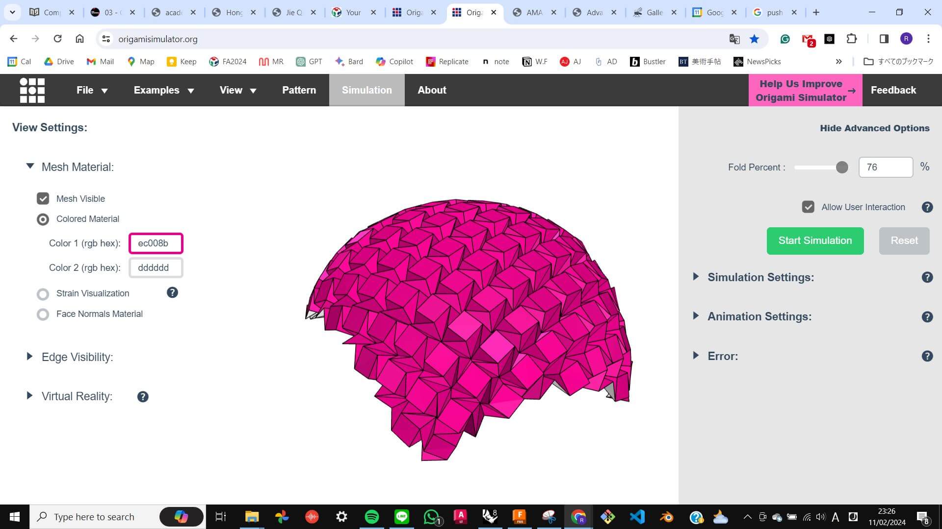
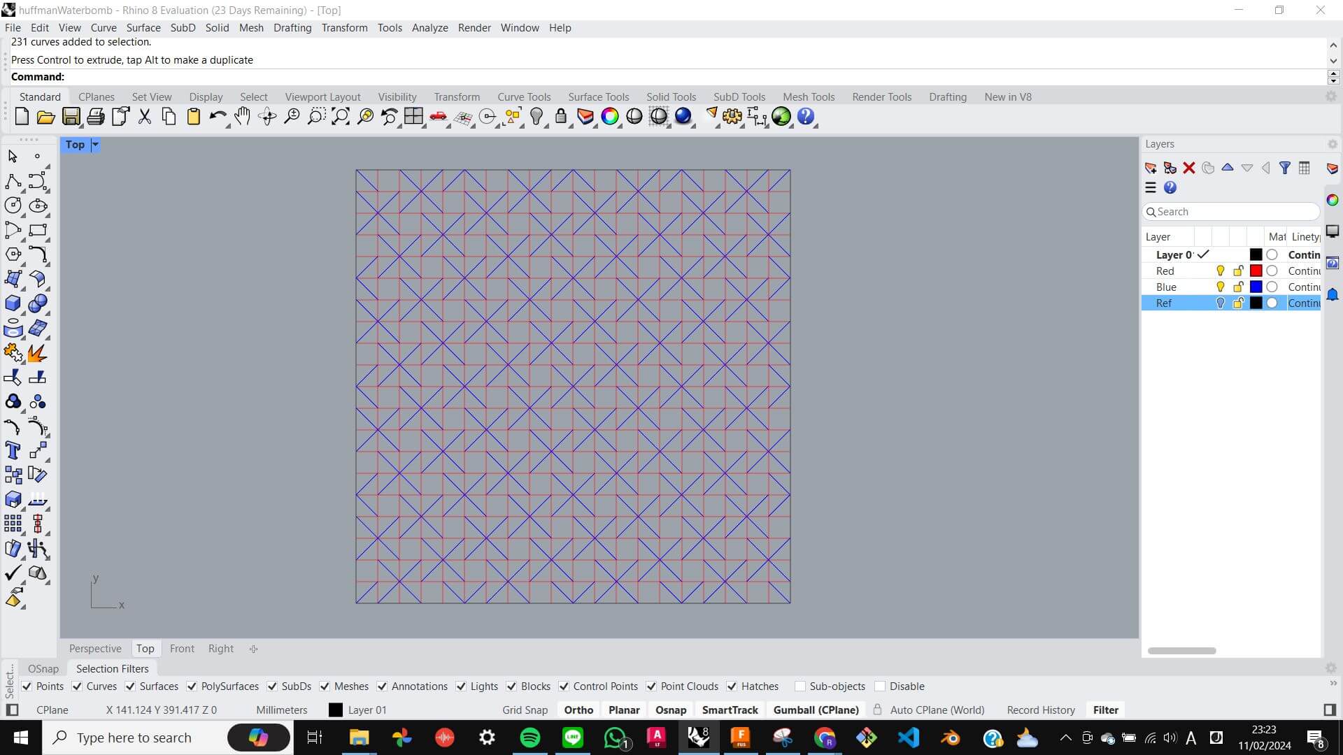
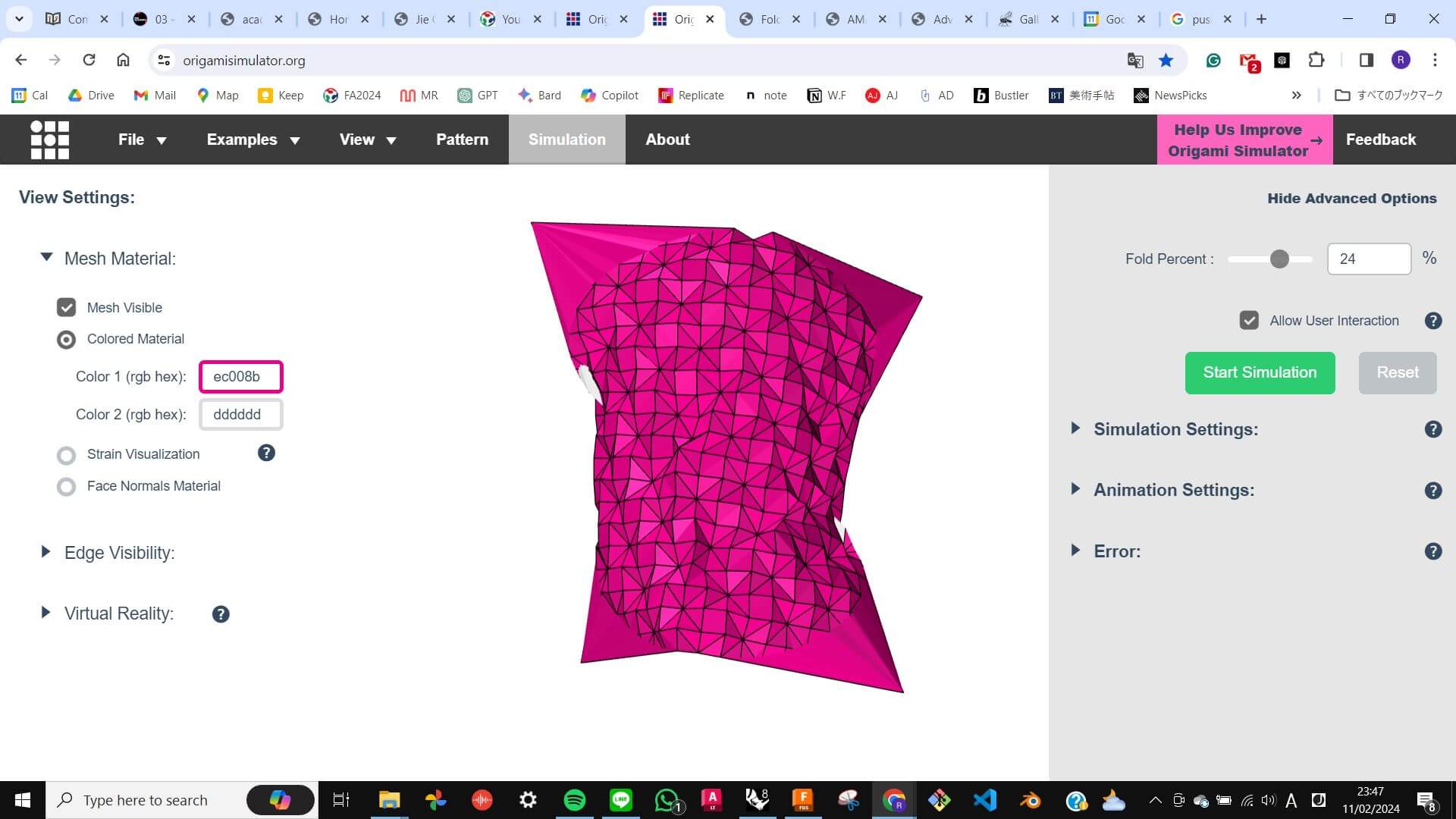
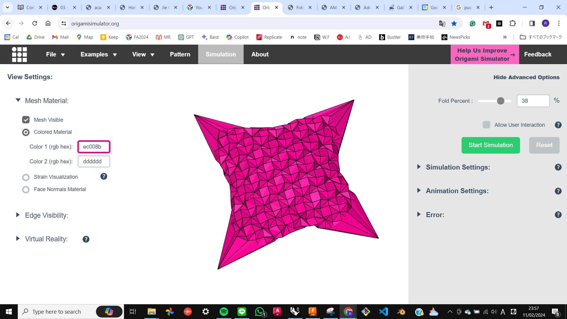
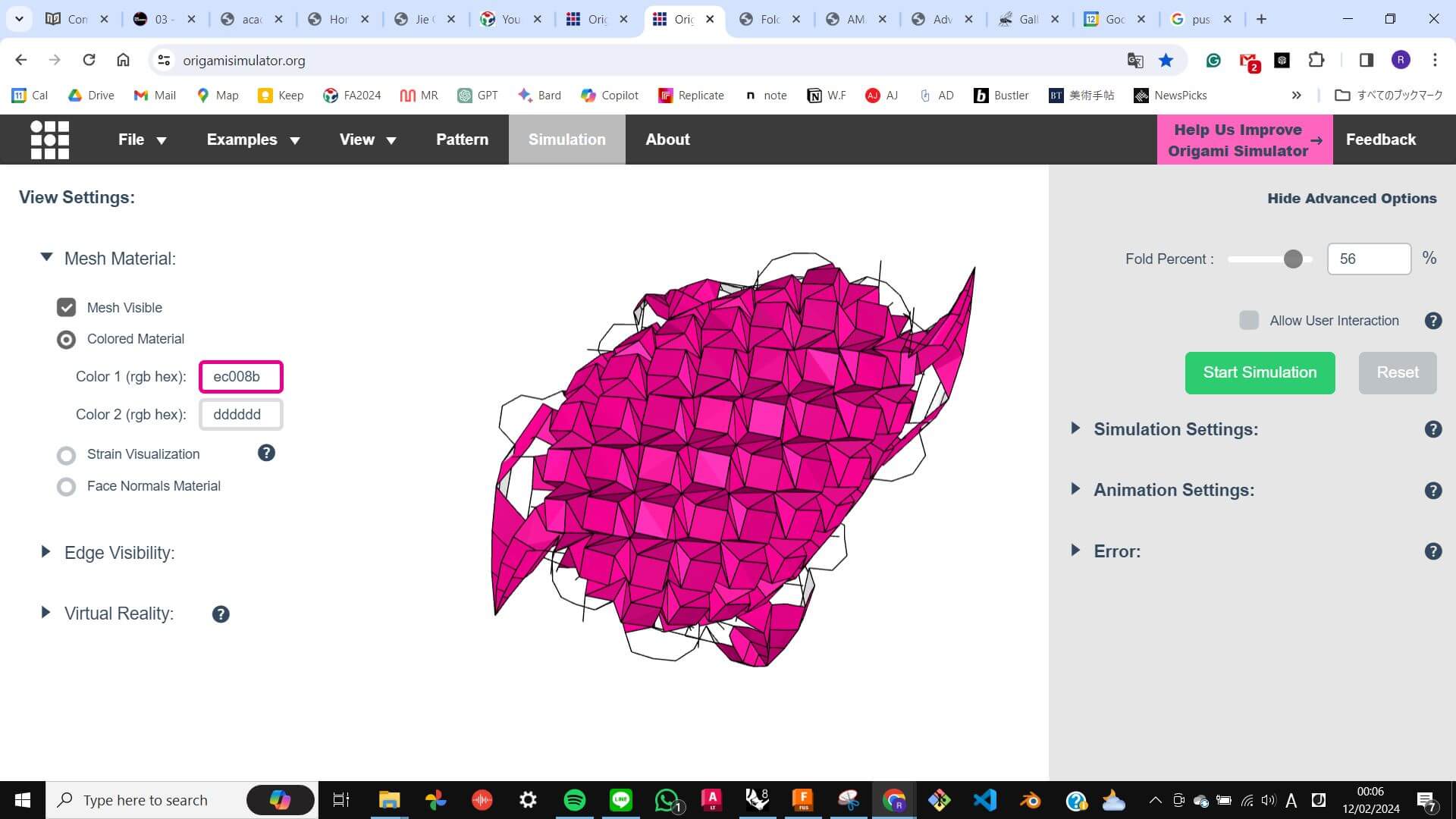
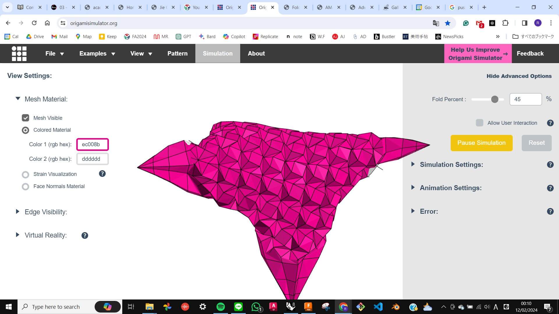
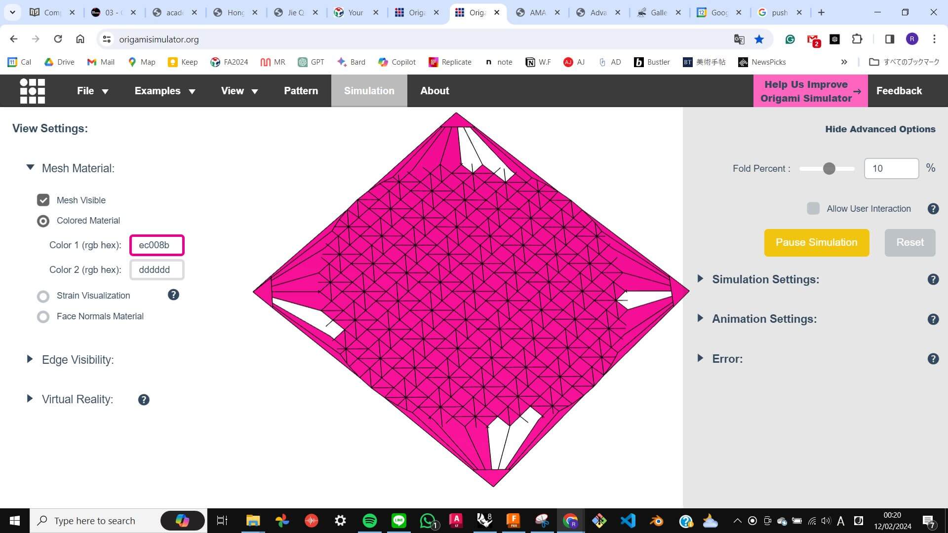
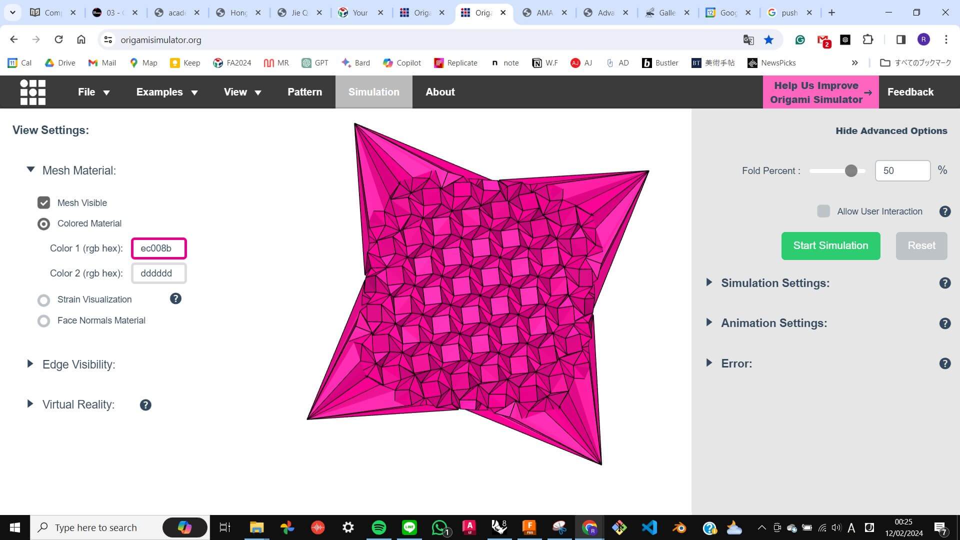
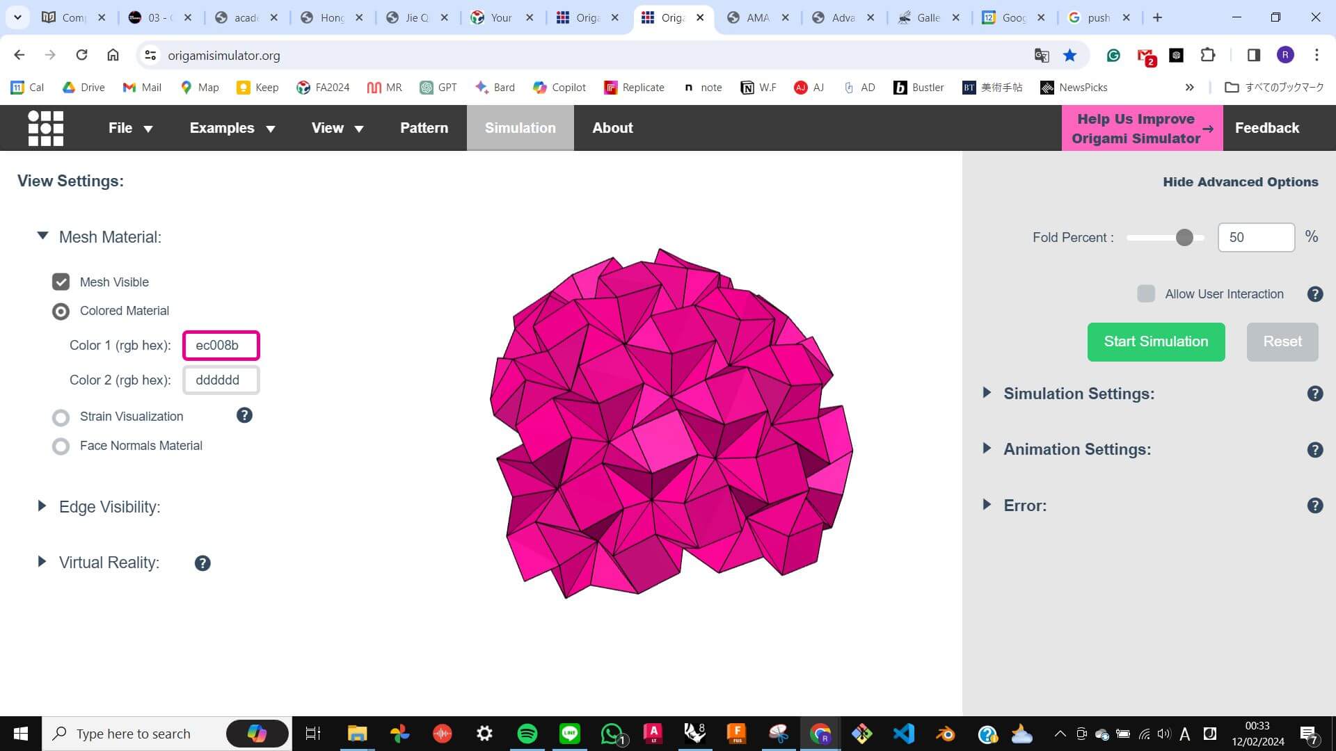
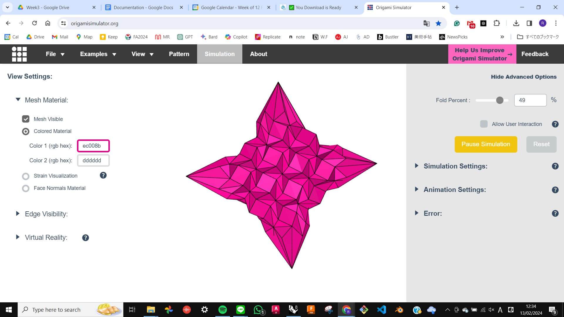
To start, I used the Origami Simulator made by Amanda Ghassaei from MIT the Center of Bits and Atoms. I looked through examples that were created previously and chose to work with the Huffman Waterbormb pattern. Because it had the shape of a dome in the simulator I thought it might be useful to experiment with this pattern for my final project.
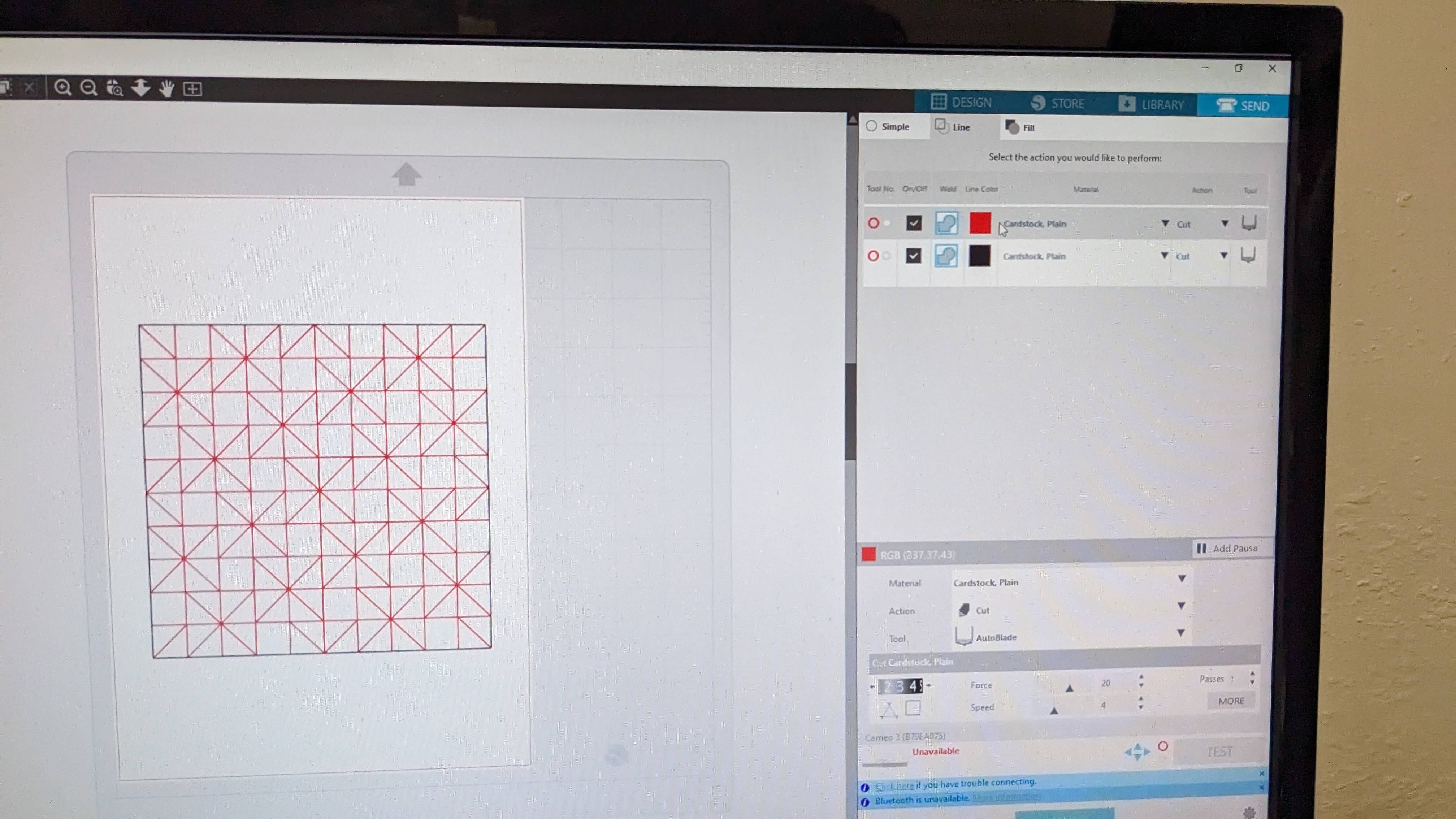
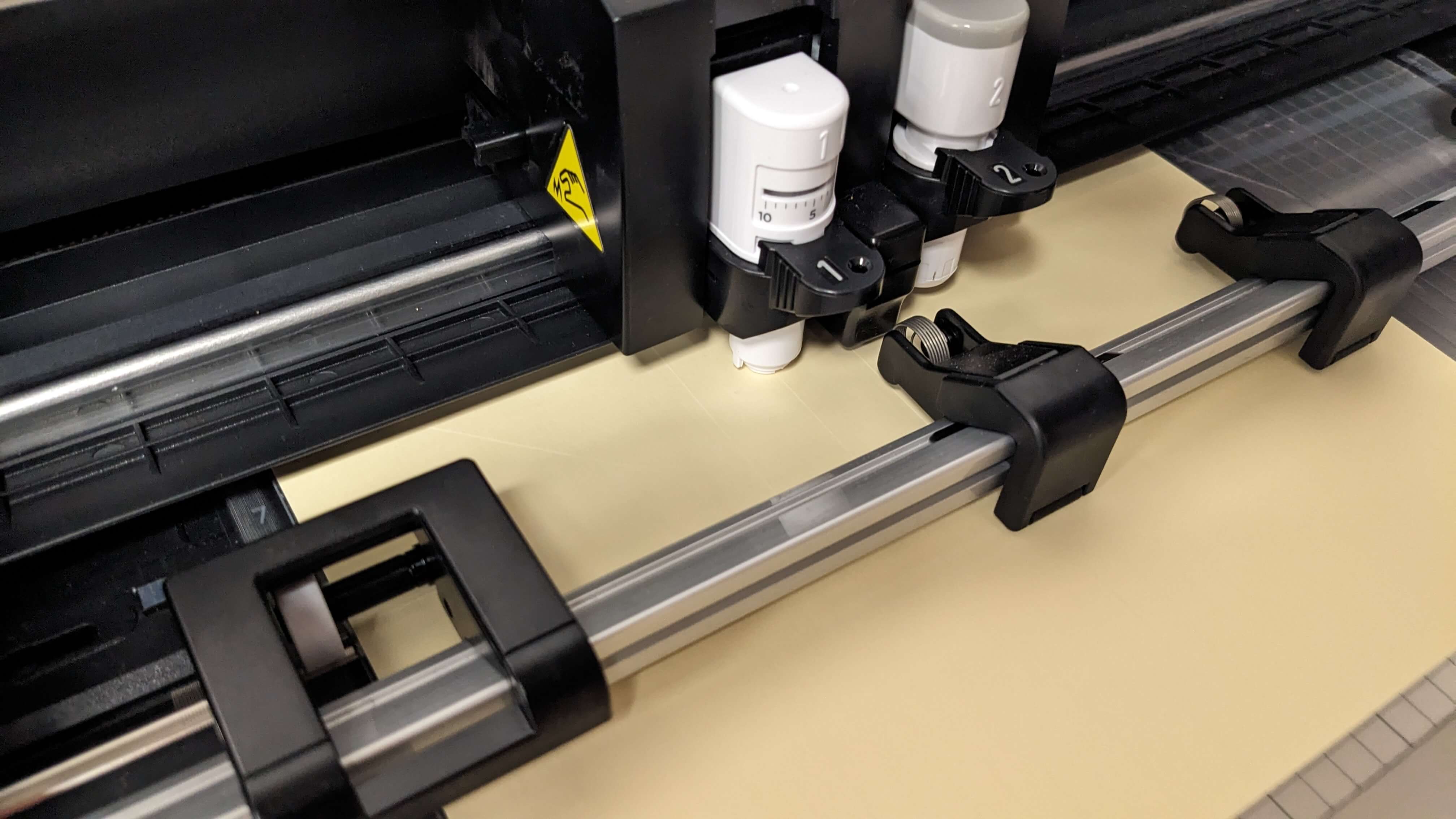
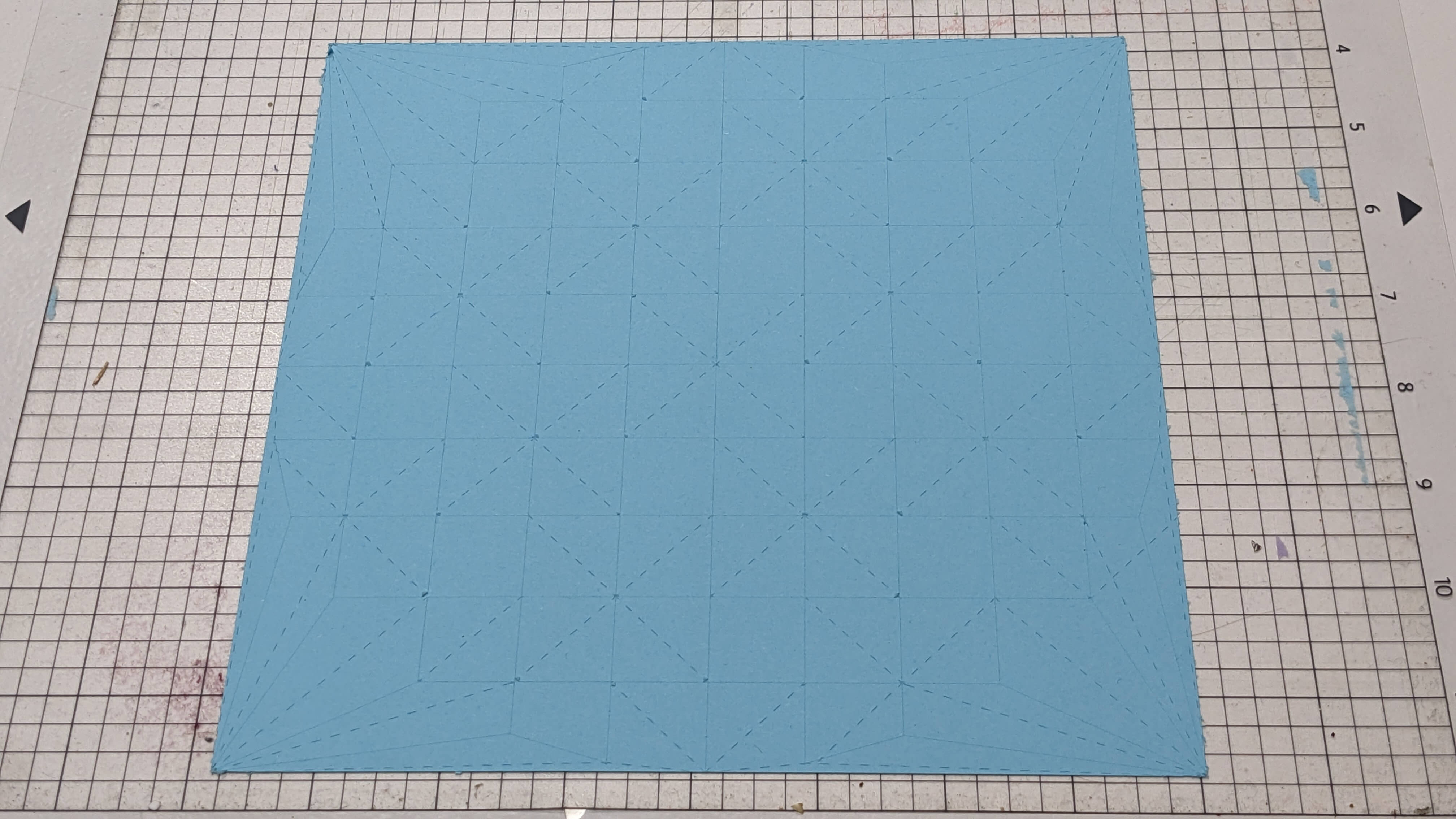
First, I downloaded a file of the pattern and recreated it in Rhino to understand how the pattern is created, then I used a Silhouette vinyl cutter to cut the pattern on card paper. First I adjusted the pressure to 3 for folding lines so that it didn't cut all the way though, however, I found out that it was a little bit strong still, so I cut another card paper with pressure 1 and it went well.
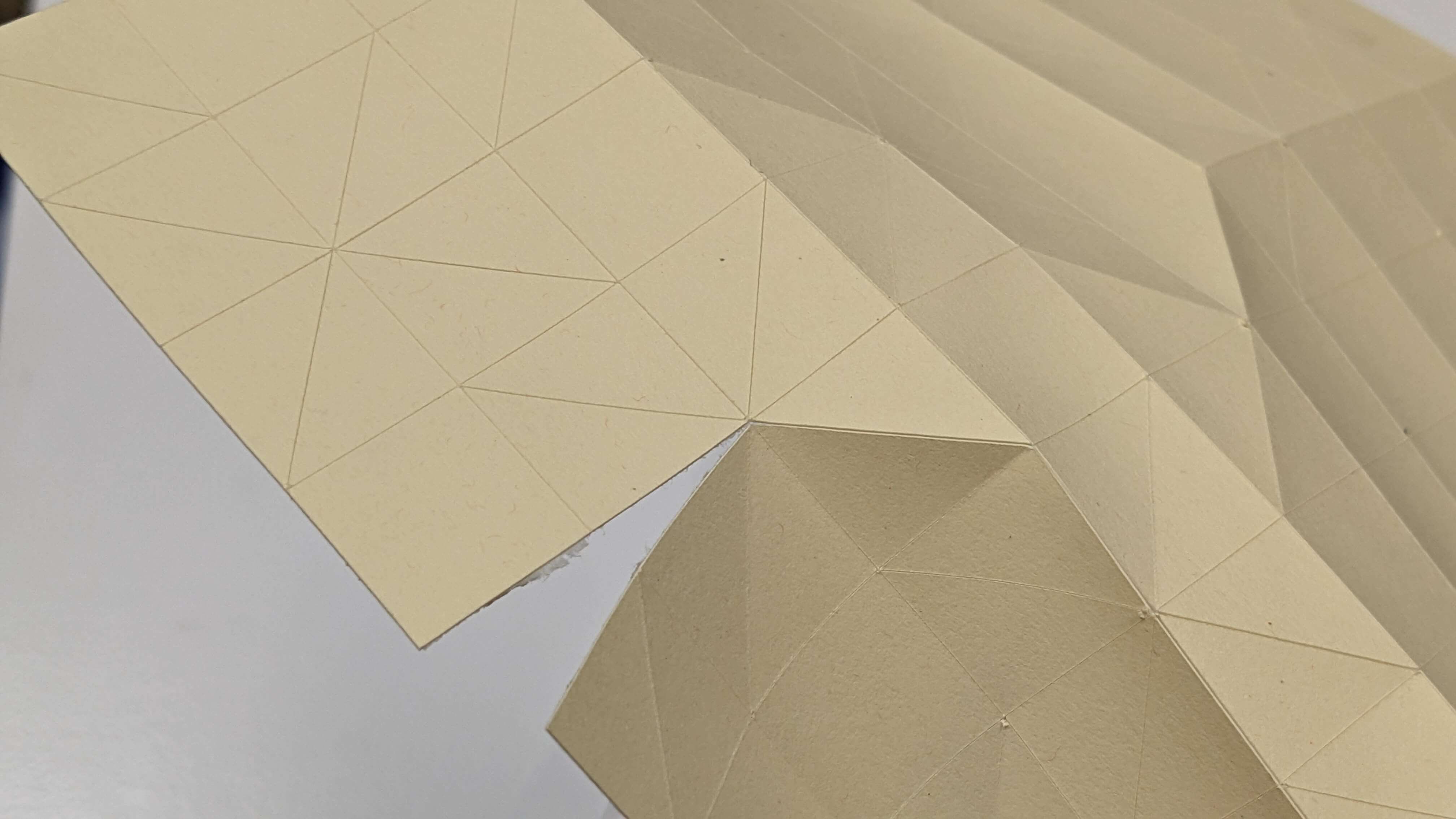
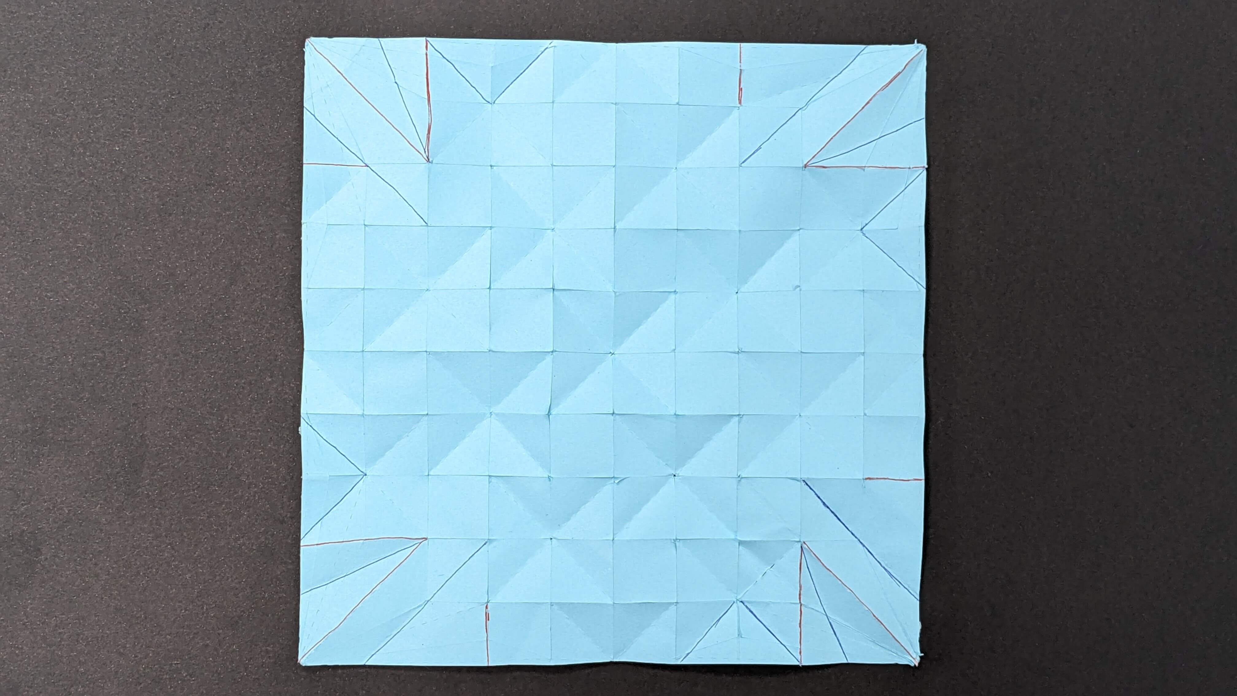
Folding the the pattern was quite difficult and took me a long time to figure out the way I was supposed to fold it. In this process, I learned that as a general rule of folding this kind of pattern, I have to start from the edges and gradually fold towards the centre.
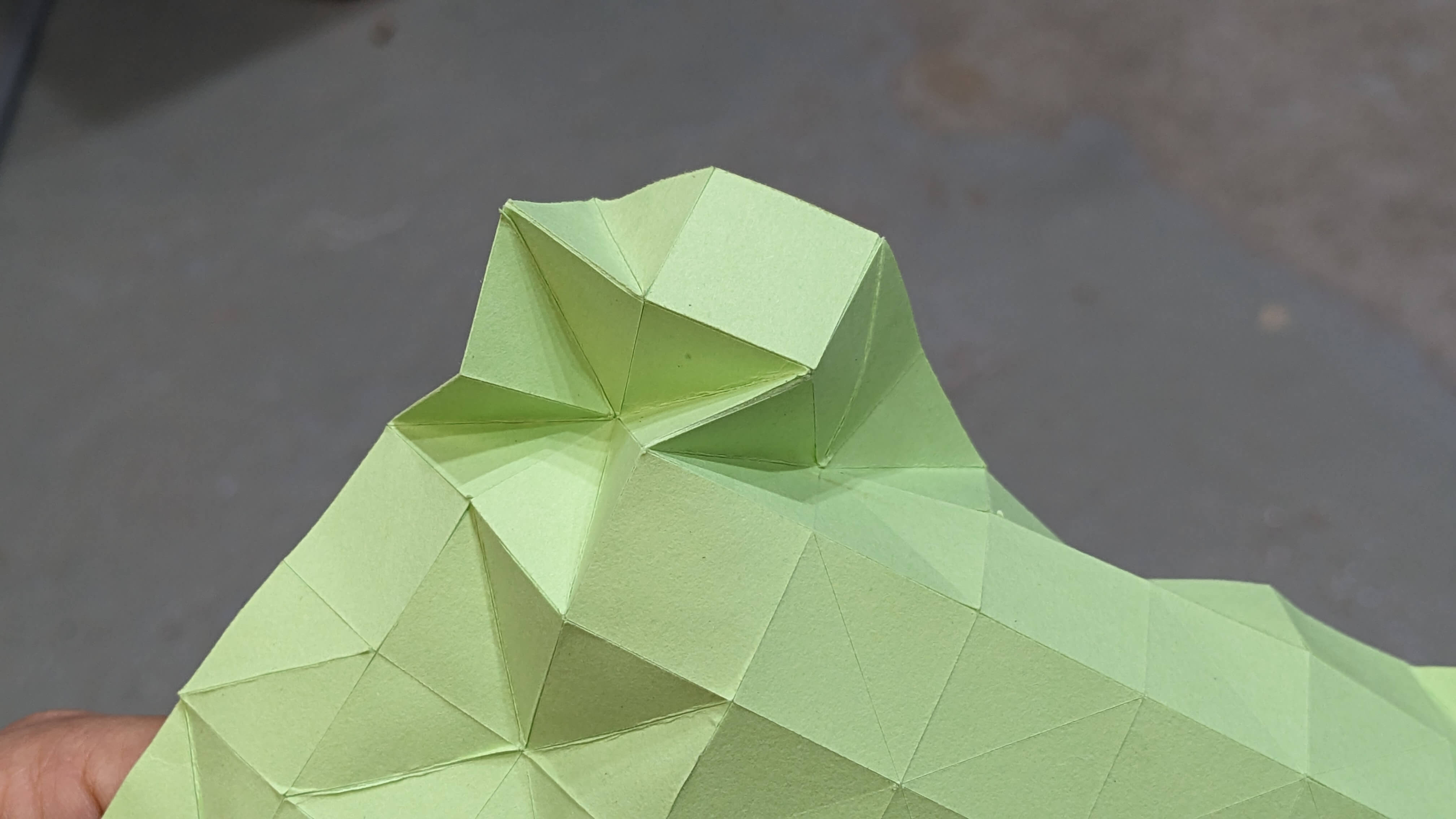
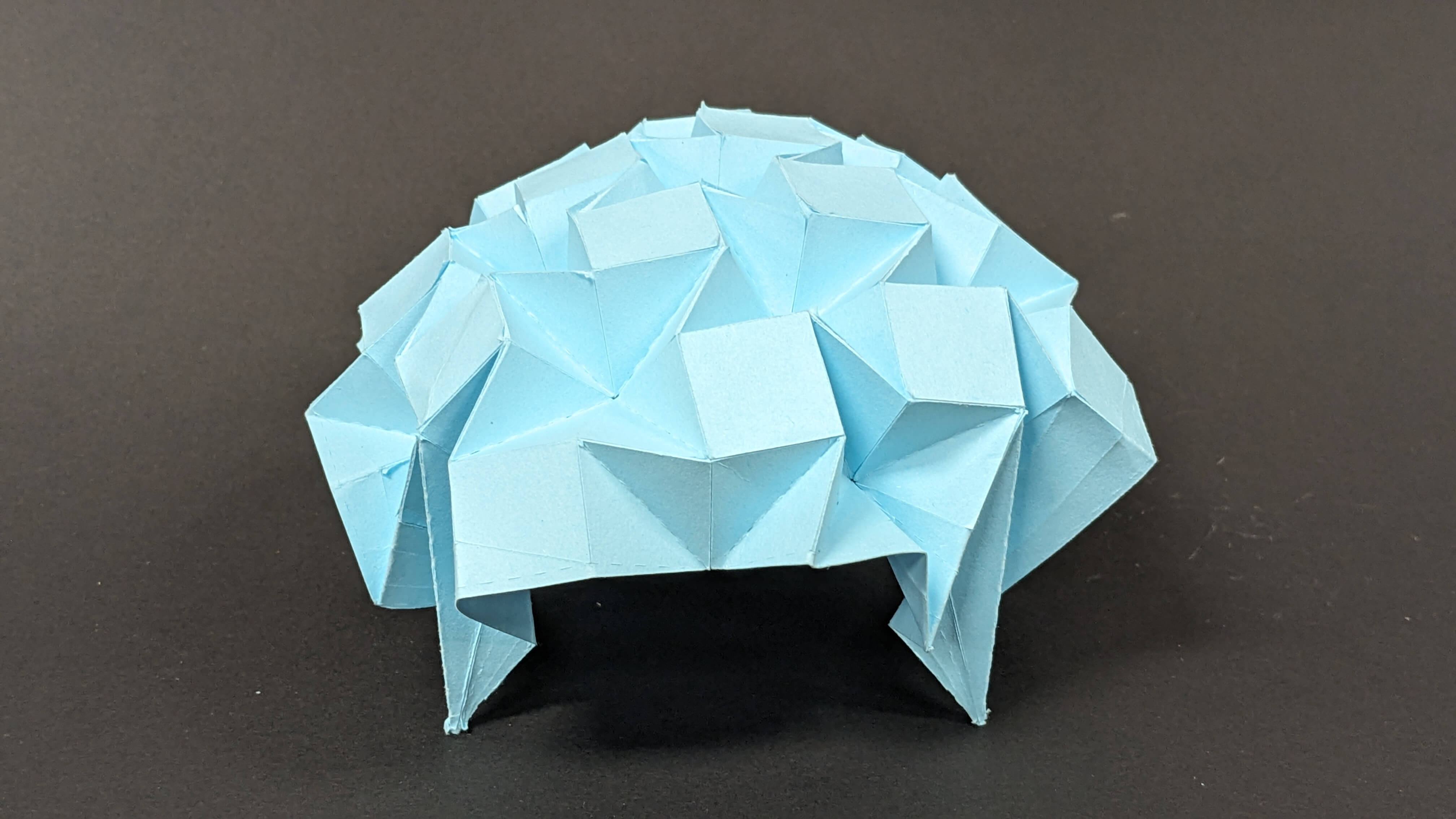
I was happy to achieve the origami shape with flexibility, however, I wanted it to stand by itself, so I started thinking about how to insert a leg for each corner just by tweaking the fold. So I adjusted the pattern in Rhino and ran the simulator to check if it worked. I did this process repeatedly for 8 times and ended up with a pattern.
To test this pattern with legs, I simply cut a card paper with the vinyl cutter in the way as last time. However, I was not able to fold it properly without destroying the leg pattern I made. So I gave up folding with my leg pattern and let the pattern fold as it wanted to be folded. In this way, I can recognise how the paper should be folded and which line of my leg pattern was making problems. After that, I was able to achieve legs like shape for each corner. At the end, I unfolded the pattern and highlighted modified lines for the leg so that I could edit in Rhino for my next origami model.
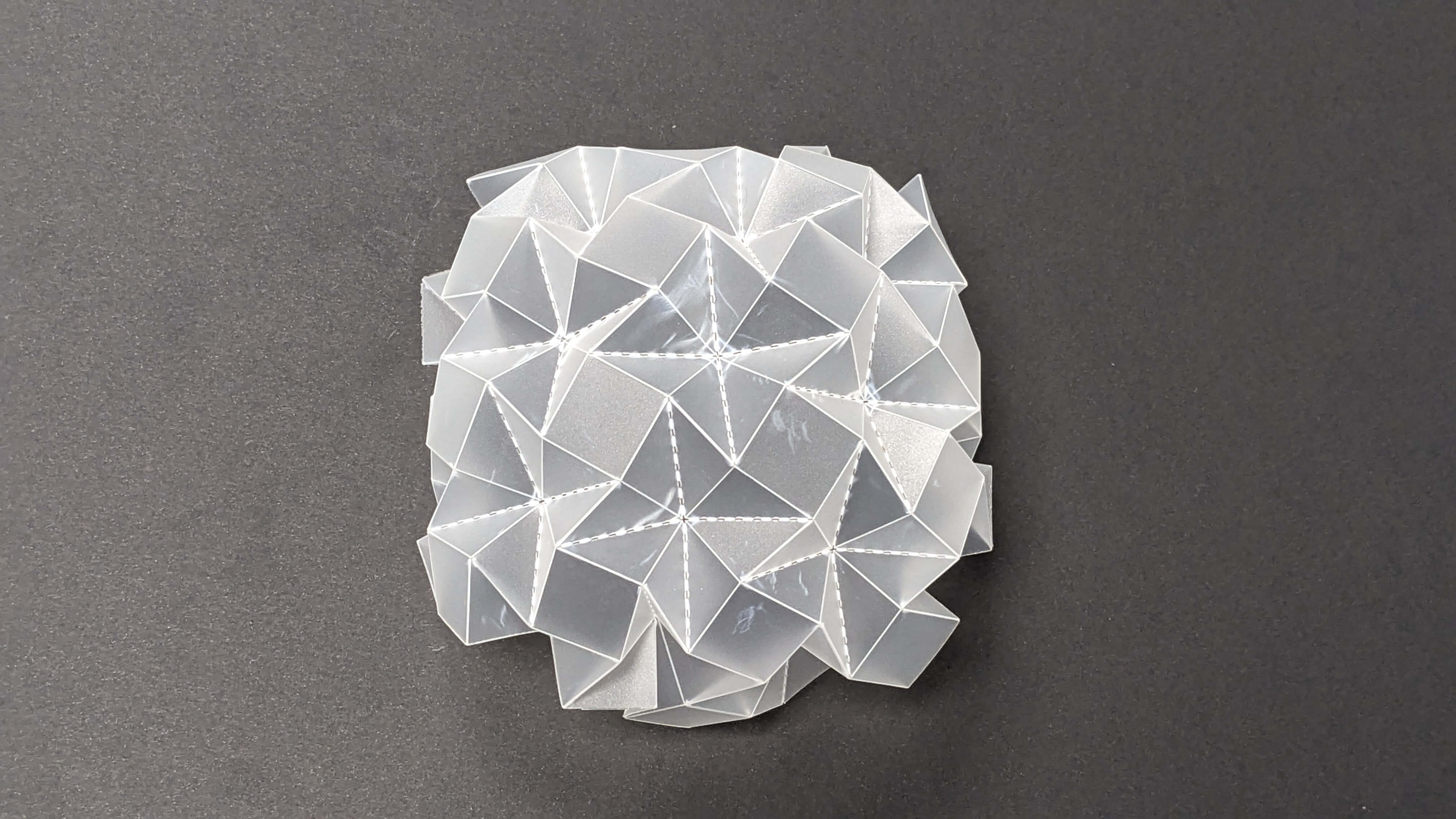
Since card paper is not a very strong material with a flexible structure, I bought a thin translucent poly sheet and tested it with an origami structure.
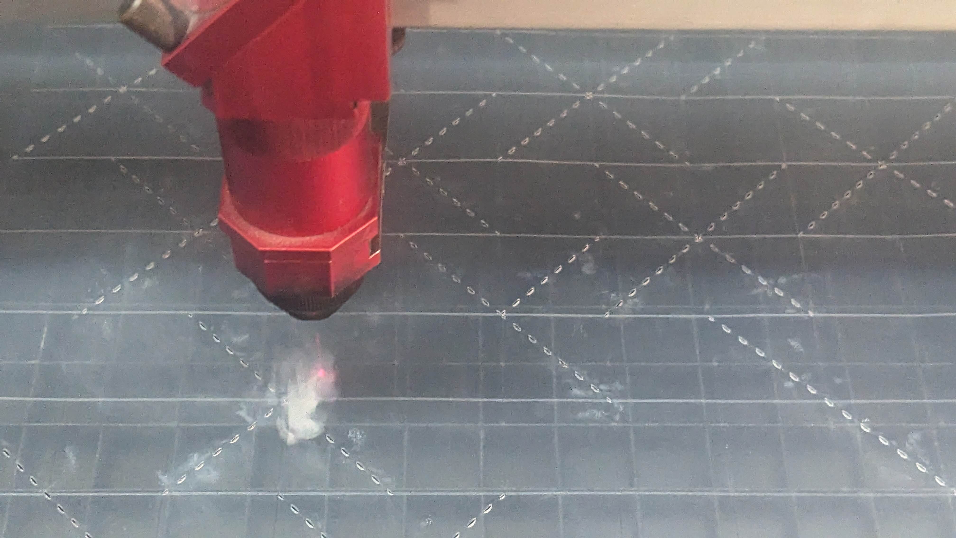
Problem
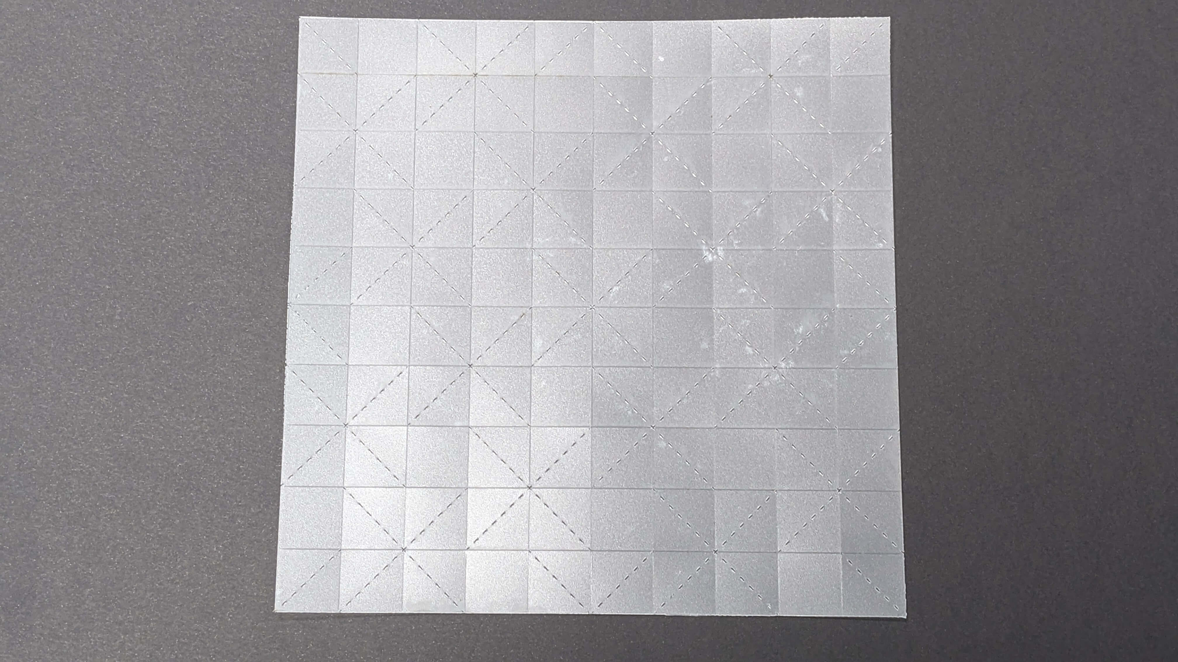
I was going to cut the poly sheet with a vinyl cutter, but the cutter could not cut through the material even with maximum pressure. After seeking advice from my tutor, I found out that this material is actually can be cut with a laser cutter. I prepared a file with 3 types of cut ( scoring line, dashed line, and edge line) Since it is a new material to cut with a laser, it was hard to guess the power, speed, and PPI setting. My tutor helped me with this, and we decided on the values by referencing values for similar material. In the end, we were able to cut the material in the first trial.
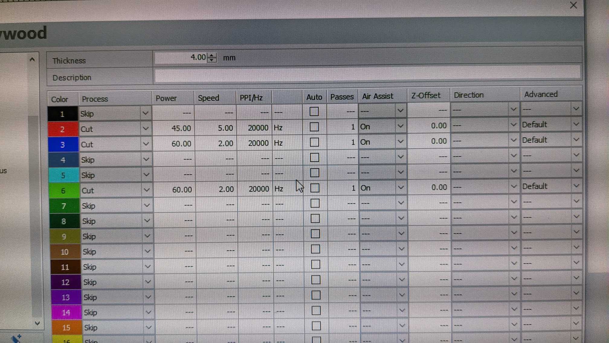
The setting for this material is
Scoring: Power 45, Speed 5, PPI 20000
Cut: Power 60, Speed 2, PPI 20000
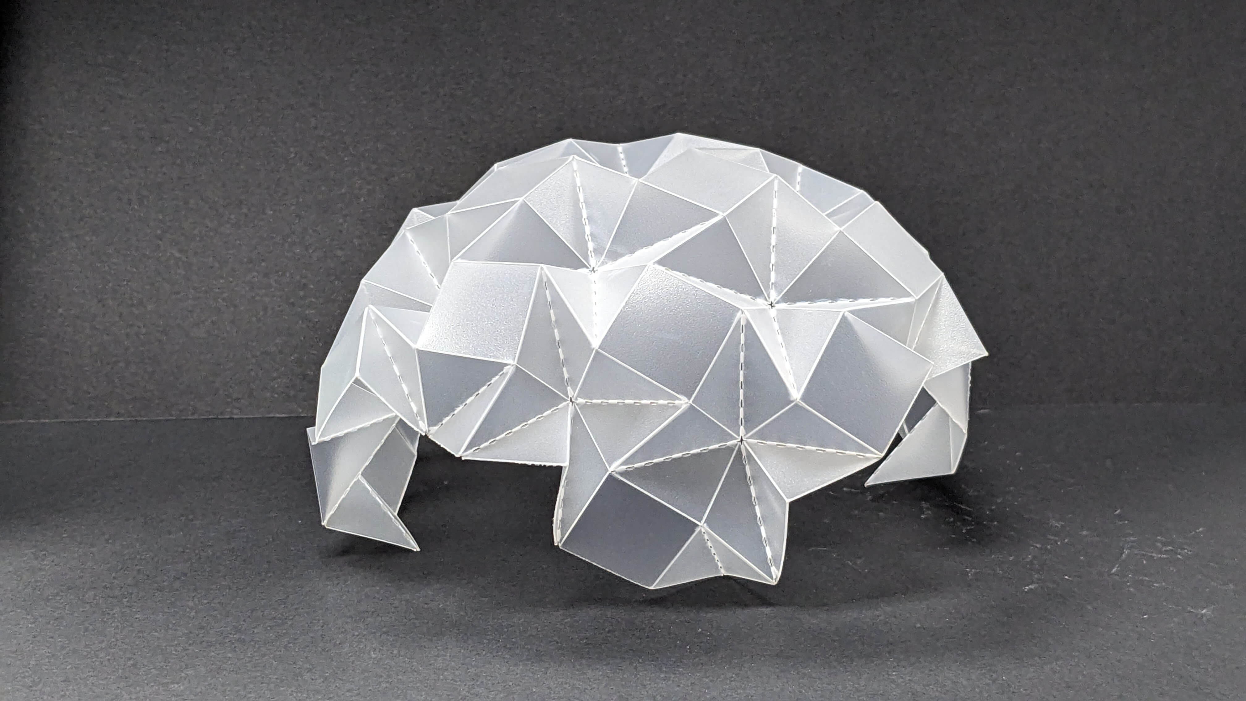
Folding this material was actually easier than folding with paper because it is strong enough to keep its surface and flexible enough to fold with the guidelines. The result was beautiful. It keeps the origami shape even when it is squished. However, it felt a little bit too strong for creating movement. I think this has to do with the ratio between the size of the pattern and the size of the object. Since this 20mm grid pattern is the smallest grid pattern for folding by hand, the option is to create a large object while keeping this 20mm grid pattern. This is something I would like to investigate further.