- Demonstrate and compare the toolchains and development workflows for available embedded architectures.
- Document your work on the group page and reflect what you learned on your individual page.
Individual assignments:
- Browse through the datasheet for your microcontroller.
- Write a program for a microcontroller, and simulate its operation, to interact (with local input &/or output devices) and communicate (with remote wired or wireless connection).
Group Assignment
we had compare different toolchains and development Workflows for embedded Architectures.
Click on this button to get it to our Group Assignment Page
Individual Assignment
Introduction to Arduino
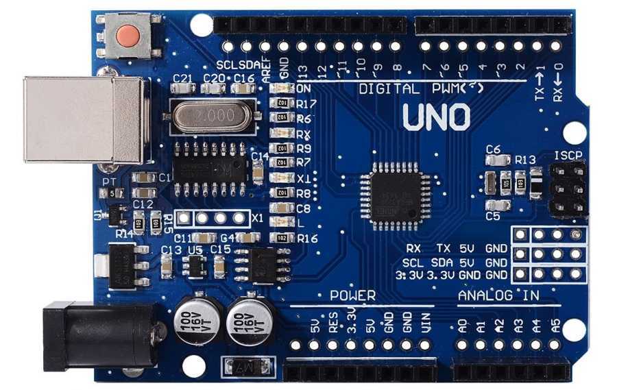
Arduino Uno is a microcontroller development board based on the ATmega328P chip. It is part of the open-source Arduino platform that makes it easy to build and program interactive electronic projects.
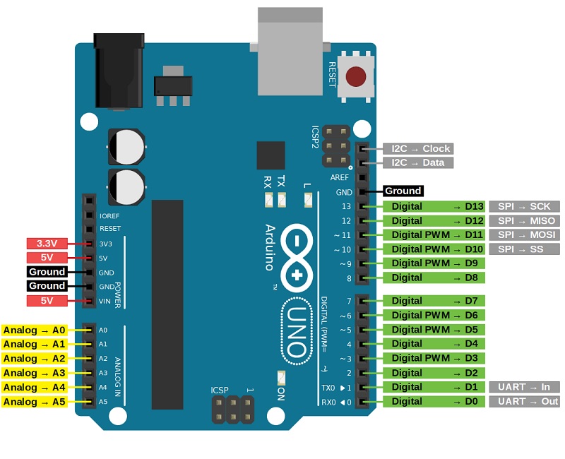
Pin diagram
The Arduino Uno board features a range of pins used for various functions. It has 14 digital input/output pins (D0–D13), with six of them (pins 3, 5, 6, 9, 10, and 11) capable of PWM output.
There are six analog input pins (A0–A5), which can also function as digital I/O if needed. Power pins include Vin for external power input (7–12V), 5V and 3.3V regulated outputs, multiple GND (ground) pins, and a RESET pin to restart the board.
For communication, the board supports UART via pins 0 (RX) and 1 (TX), I2C using A4 (SDA) and A5 (SCL), and SPI through pins 10 (SS), 11 (MOSI), 12 (MISO), and 13 (SCK).
Additional features include an AREF pin for analog reference voltage and a 6-pin ICSP header for programming via SPI.
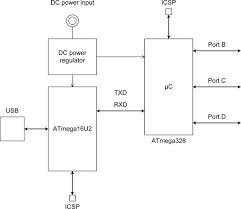
Block diagram
The Arduino Uno block diagram is a simplified visual representation that illustrates the main functional components of the Arduino Uno board and how they are interconnected.
It typically shows key parts such as the microcontroller (ATmega328P), power supply circuits, input/output pins, communication interfaces (USB, UART, I2C, SPI), clock oscillator, and reset circuitry.
This diagram helps in understanding the overall architecture and workflow of the Arduino Uno, making it easier to grasp how the board processes inputs, controls outputs, and communicates with other devices.
Specifications
Microcontroller: Tensilica Xtensa LX6 (dual-core)
Operating Voltage: 3.3V
Input Voltage (recommended): 5V via USB or 7–12V via VIN
Input Voltage (limits): 3.0–3.6V (internal logic)
Digital I/O Pins: 34 (multipurpose)
Analog Input Pins: 18 (12-bit ADC)
Analog Output Pins: 2 (8-bit DAC)
PWM Channels: 16
Touch Sensing Pins: 10
Communication Interfaces: UART, SPI, I2C, I2S, CAN
Wi-Fi: 802.11 b/g/n (2.4 GHz)
Bluetooth: v4.2 (Classic and BLE)
SRAM: 520 KB
Flash Memory: Typically 4 MB (external)
Clock Speed: Up to 240 MHz
USB Connection: Micro USB (via onboard UART bridge)
Built-in Features: Hall Sensor, Temperature Sensor, Cryptographic Hardware Acceleration
ESP32 is a low-cost, low-power system-on-chip (SoC) microcontroller developed by Espressif Systems.
It features dual-core processors, integrated Wi-Fi and Bluetooth connectivity, and a rich set of peripherals, making it ideal for Internet of Things (IoT) applications, embedded systems, and wireless communication projects.
The ESP32 supports various interfaces like SPI, I2C, UART, ADC, DAC, and PWM, providing flexibility for diverse hardware designs.
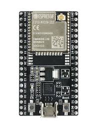
Pin diagram
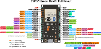
The ESP32 microcontroller features multiple GPIO pins that support a wide range of functions including digital input/output, analog input, PWM, touch sensing, and communication protocols.
The chip has 34 programmable GPIO pins, although some pins have special functions or restrictions. Key pins include GPIO 0 to GPIO 39, with certain pins dedicated to specific purposes like ADC (Analog to Digital Converter), DAC (Digital to Analog Converter), capacitive touch sensors, and RTC (Real-Time Clock) functions.
The ESP32 also supports interfaces such as UART, SPI, I2C, and CAN on various pins. Power pins include 3.3V and multiple ground pins. Some GPIOs are input-only or have internal pull-up/down resistors.
The pinout varies slightly depending on the ESP32 module version, but generally offers versatile connectivity options for sensors, displays, and communication modules.
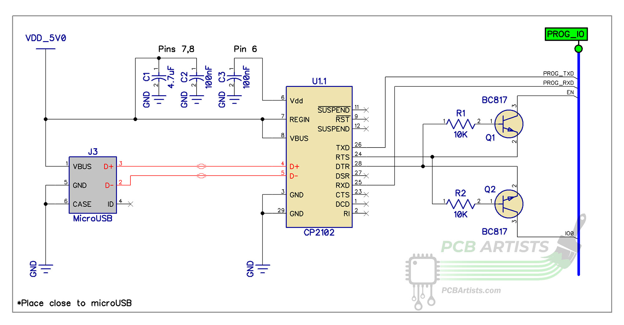
Block diagram
The ESP32 block diagram represents the internal architecture and functional units of the ESP32 system-on-chip (SoC) developed by Espressif Systems.
It highlights the main components that work together to provide processing power, wireless communication, and peripheral control in embedded and IoT applications.
At the core, the ESP32 includes a dual-core Tensilica Xtensa LX6 microprocessor, capable of running at up to 240 MHz, providing powerful parallel processing for multitasking. It features built-in Wi-Fi (802.11 b/g/n) and Bluetooth 4.2 (Classic and BLE) transceivers, allowing seamless wireless connectivity.
The Memory Block includes SRAM, ROM, and support for external flash via SPI, ensuring flexible code and data storage. The Clock Generator and Power Management Unit (PMU) manage system timing and efficient power use across various operating modes (active, sleep, deep sleep).
Specifications
Microcontroller: Tensilica Xtensa LX6 (dual-core)
Operating Voltage: 3.3V
Input Voltage (recommended): 5V via USB or 7–12V via VIN
Input Voltage (limits): 3.0–3.6V (internal logic)
Digital I/O Pins: 34 (multipurpose)
Analog Input Pins: 18 (12-bit ADC)
Analog Output Pins: 2 (8-bit DAC)
PWM Channels: 16
Touch Sensing Pins: 10
Communication Interfaces: UART, SPI, I2C, I2S, CAN
Wi-Fi: 802.11 b/g/n (2.4 GHz)
Bluetooth: v4.2 (Classic and BLE)
SRAM: 520 KB
Flash Memory: Typically 4 MB (external)
Clock Speed: Up to 240 MHz
USB Connection: Micro USB (via onboard UART bridge)
Built-in Features: Hall Sensor, Temperature Sensor, Cryptographic Hardware Acceleration
Electronic simulation tools allow users to design and test electronic circuits virtually.
They are used by engineers, hobbyists, and students to visualize circuit behavior without needing physical components.
Types of Electronics Stimulation
There are two types of stimulation:
1) Online Stimulation
2) Offline Stimulation
1) Online Electronics Simulation
Online simulation refers to the process of designing and testing electronic circuits using web-based platforms that run entirely in a browser.
These tools do not require any installation and allow users to simulate, code, and view circuit behavior from anywhere with an internet connection.
Examples
Tinkercad Circuits
Wokwi
CircuitLab
2) Offline Electronics Simulation
Offline simulation involves using installed software on a local computer to model and analyze electronic circuits.
These tools typically offer more advanced features, greater accuracy, and are suitable for professional and complex circuit design without relying on an internet connection.
Examples
Proteus Design Suite
LTspice
Multisim
Tinkercad
Tinkercad is a free, web-based 3D design and electronics simulation tool developed by Autodesk.
It allows users to create 3D models, simulate electronic circuits, and write and test Arduino code in a virtual environment — all through an easy-to-use drag-and-drop interface.
Follow the Steps Below:
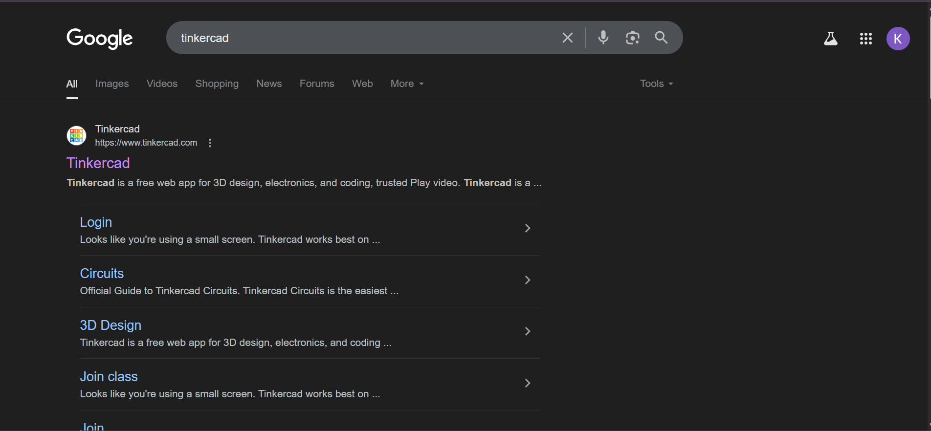
Step 1: Visit the Tinkercad Website
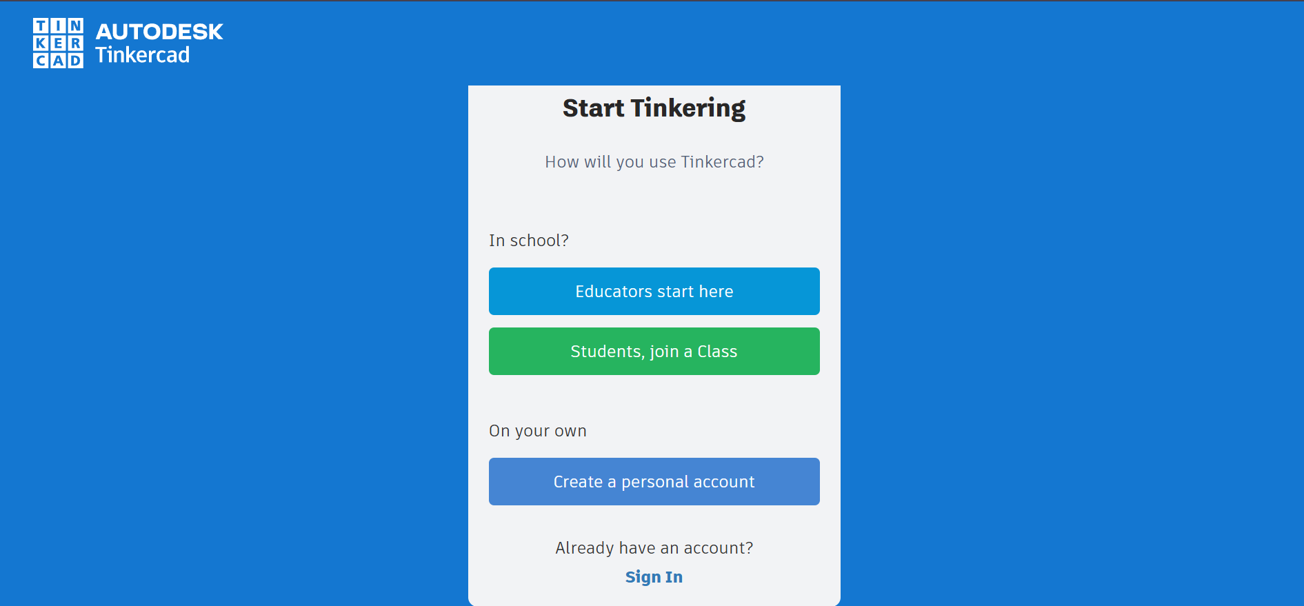
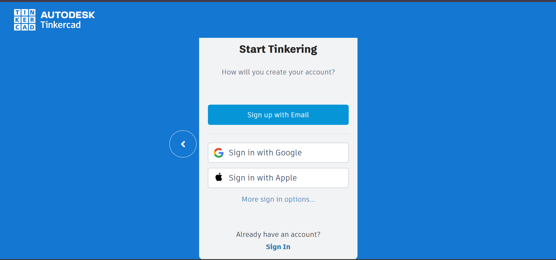
Step 2: Click on “Join Now” or “Sign Up”
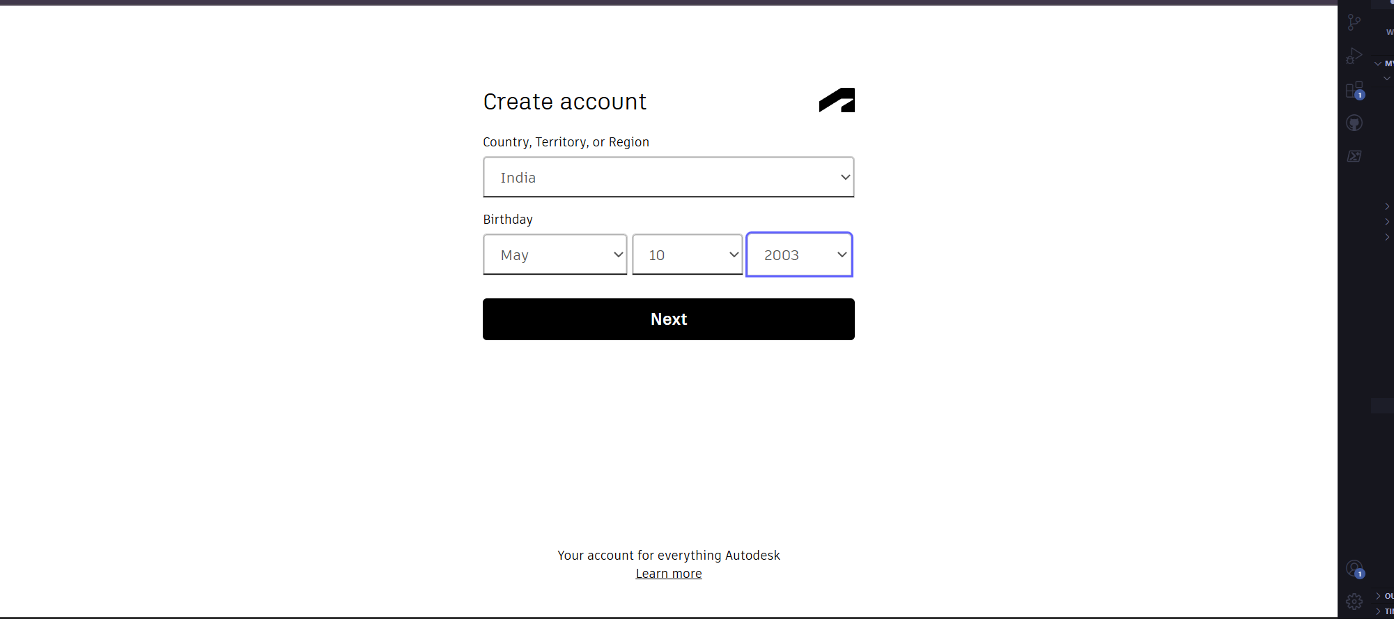
Step 3: Choose ‘Create a Personal Account’
Step 4: Sign Up with Email
Step 5: Verify Your Email
Step 6: Log in to Tinkercad
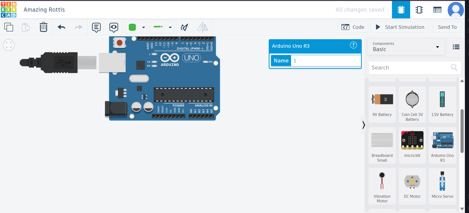
Step 7: Access the Circuits Workspace
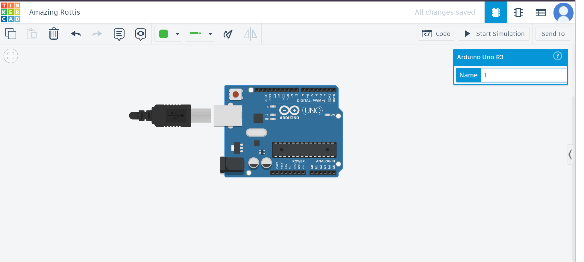
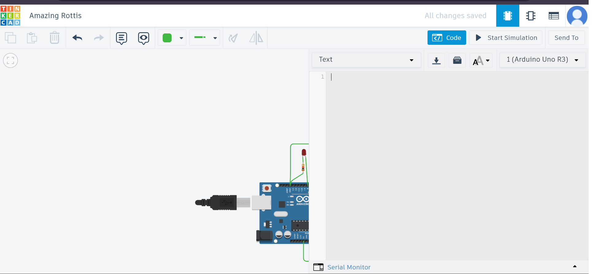
Step 8: Start Building Circuits
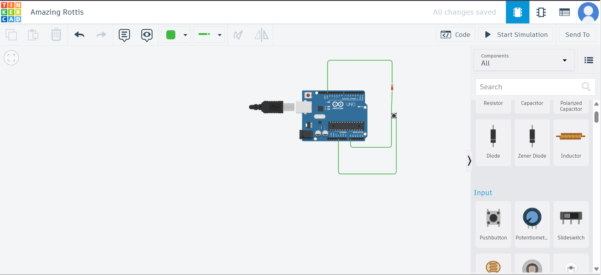
Step 9: Add Components and Wires
Step 10: Place and Arrange the Components
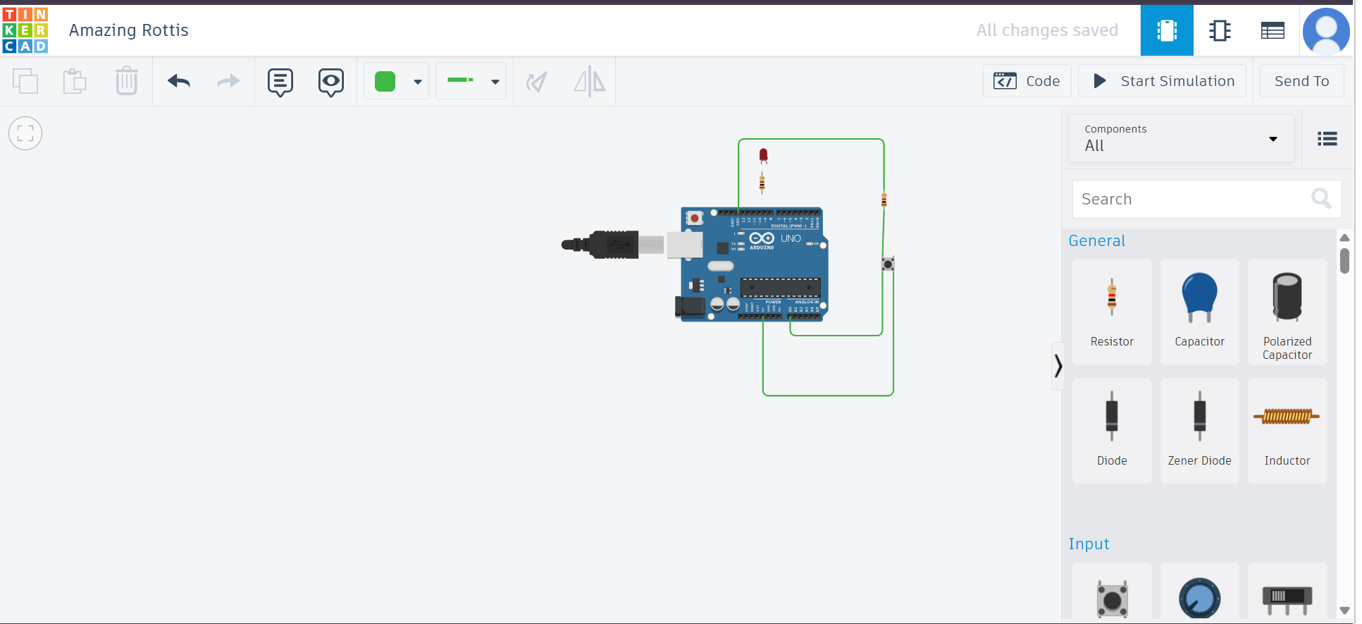
Step 11: Add Resistors and LEDs
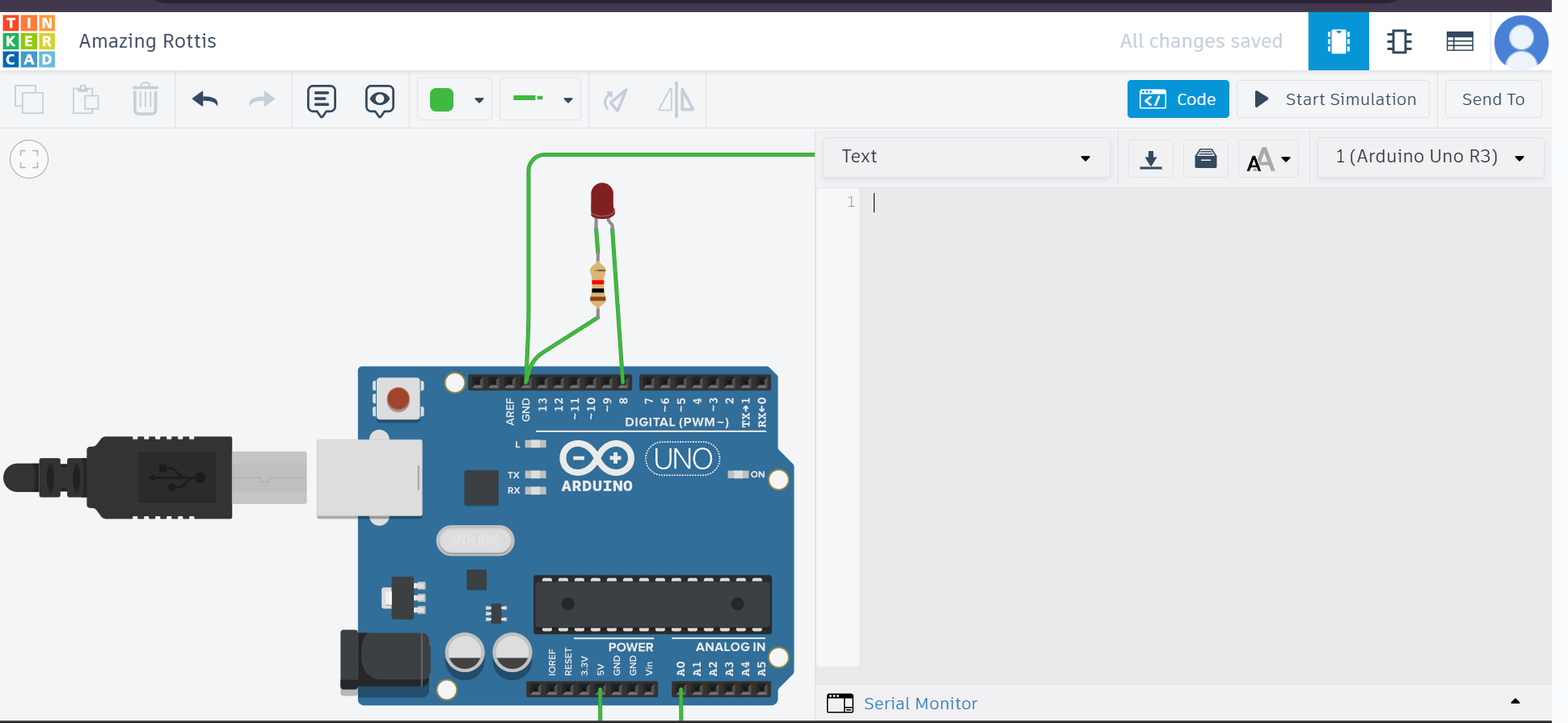
Step 12: Use Breadboard View
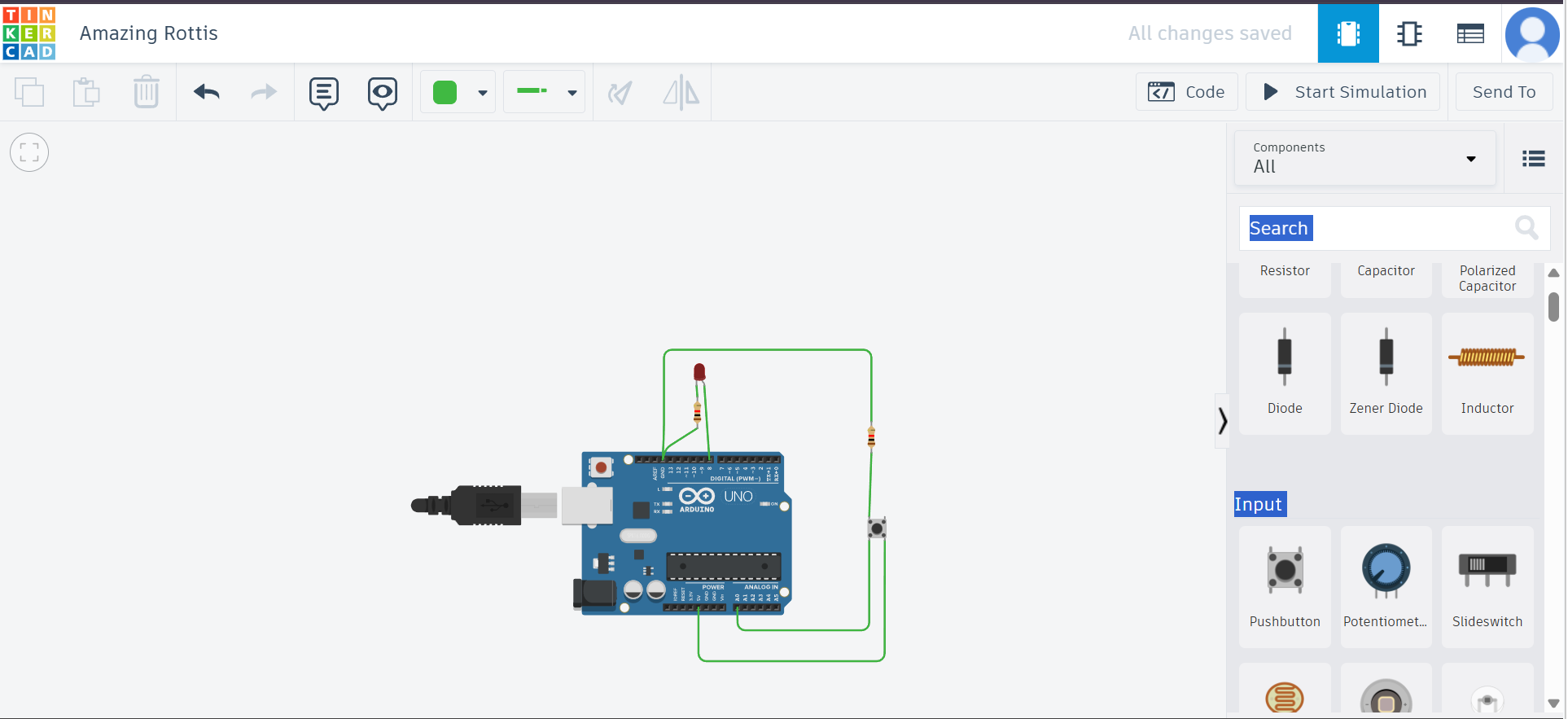
Step 13: Connect Components
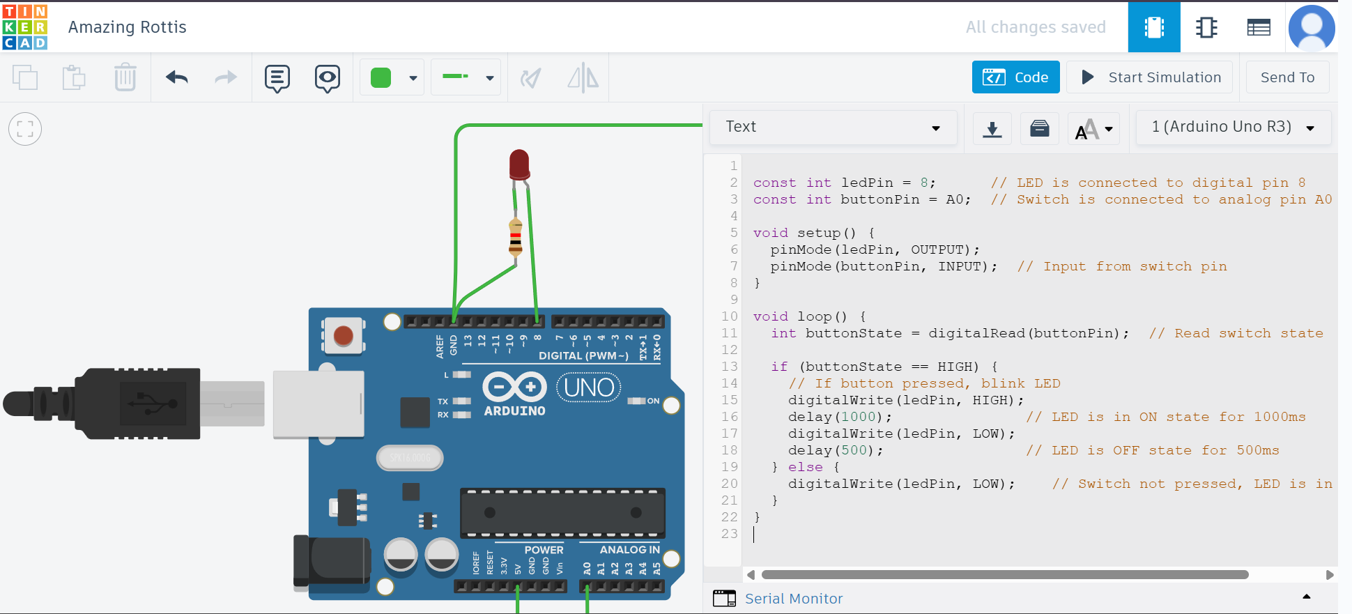
Step 14: Upload or Write Arduino Code
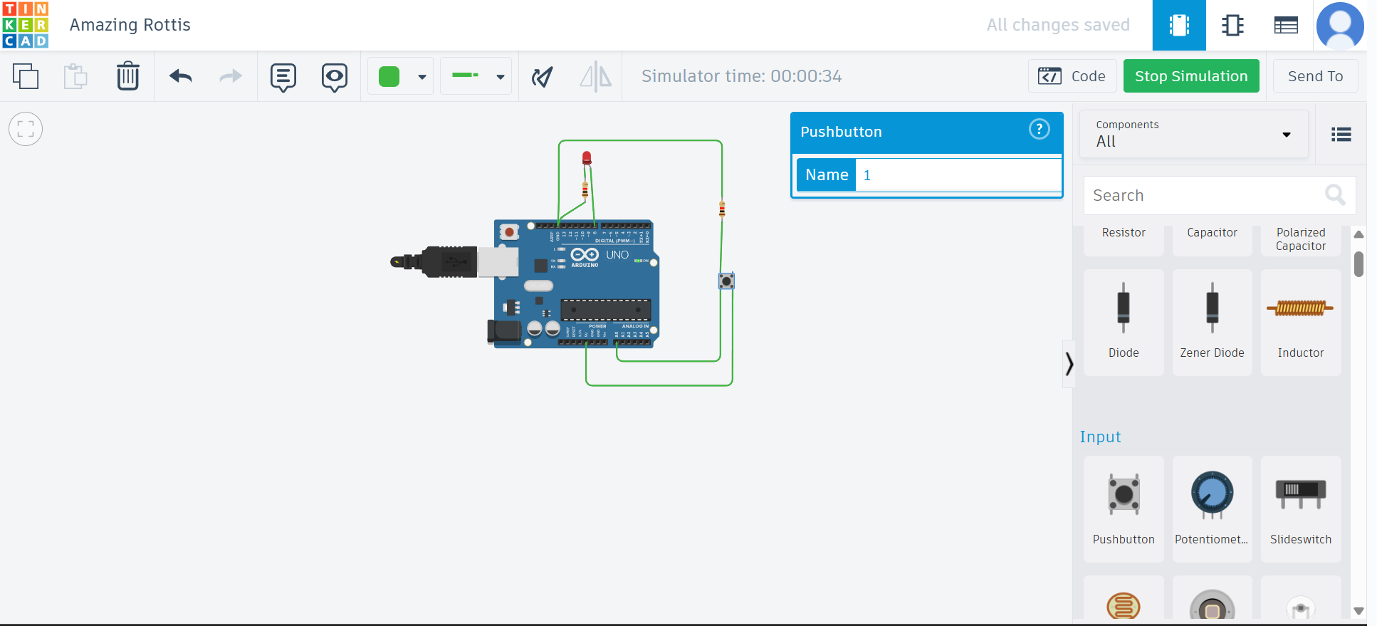
Step 15: Start Simulation
Step 16: View the Output
LED Blinking on Button Press Using Arduino Code
const int ledPin = 8;      // LED is connected to digital pin 8
const int buttonPin = A0;  // Switch is connected to analog pin A0

void setup() {
  pinMode(ledPin, OUTPUT);
  pinMode(buttonPin, INPUT);  // Input from switch pin
}

void loop() {
  int buttonState = digitalRead(buttonPin);  // Read switch state

  if (buttonState == HIGH) {
    // If button pressed, blink LED
    digitalWrite(ledPin, HIGH);
    delay(1000);               // LED is in ON state for 1000ms
    digitalWrite(ledPin, LOW);
    delay(500);                // LED is OFF state for 500ms
  } else {
    digitalWrite(ledPin, LOW);    // Switch not pressed, LED is in OFF state
  }
}
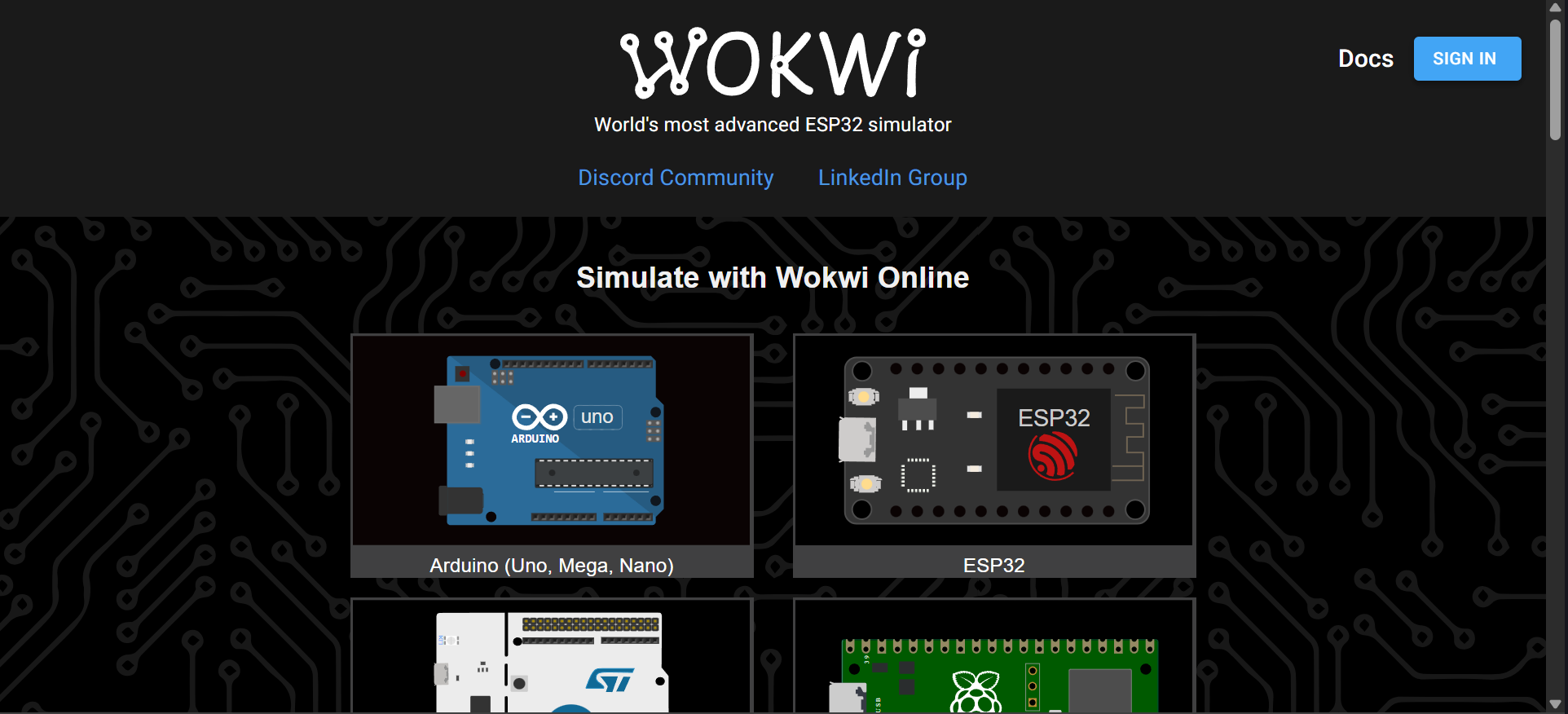
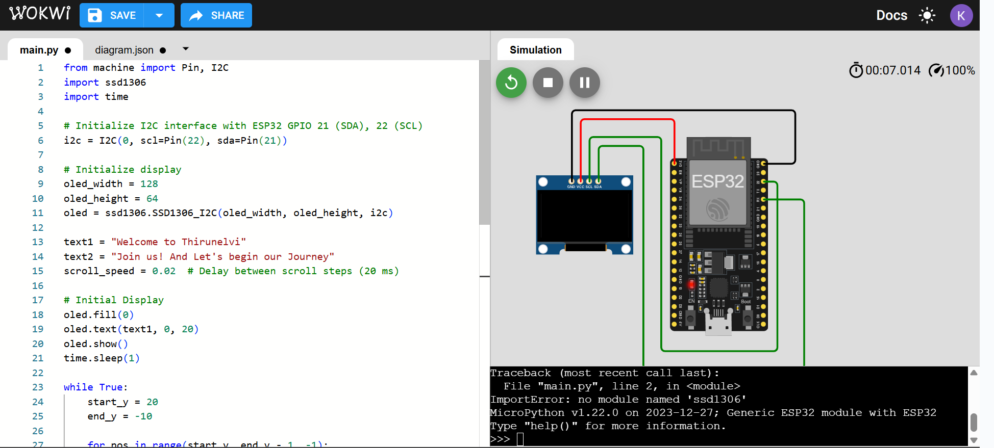
Wokwi
Wokwi is an online simulation platform for designing, simulating and testing electronics projects involving microcontrollers like Arduino, ESP32 and Raspberry Pi Pico.
It allows for project creation and testing directly in the browser making it ideal for prototyping, learning and testing without physical hardware.
I used Wokwi to conduct simulations
Follow the Steps Below:
Step 1: Visit the Wokwi Website
Step 2: Click on “Sign Up”
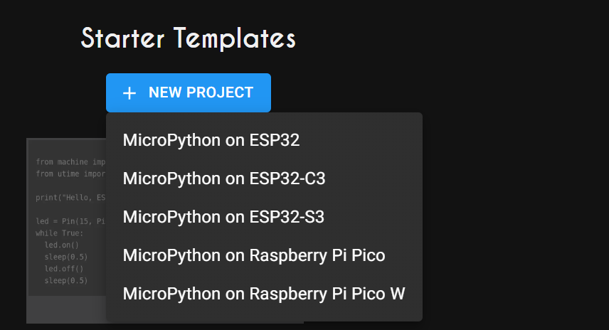
Step 3: Scroll down the list of templates.
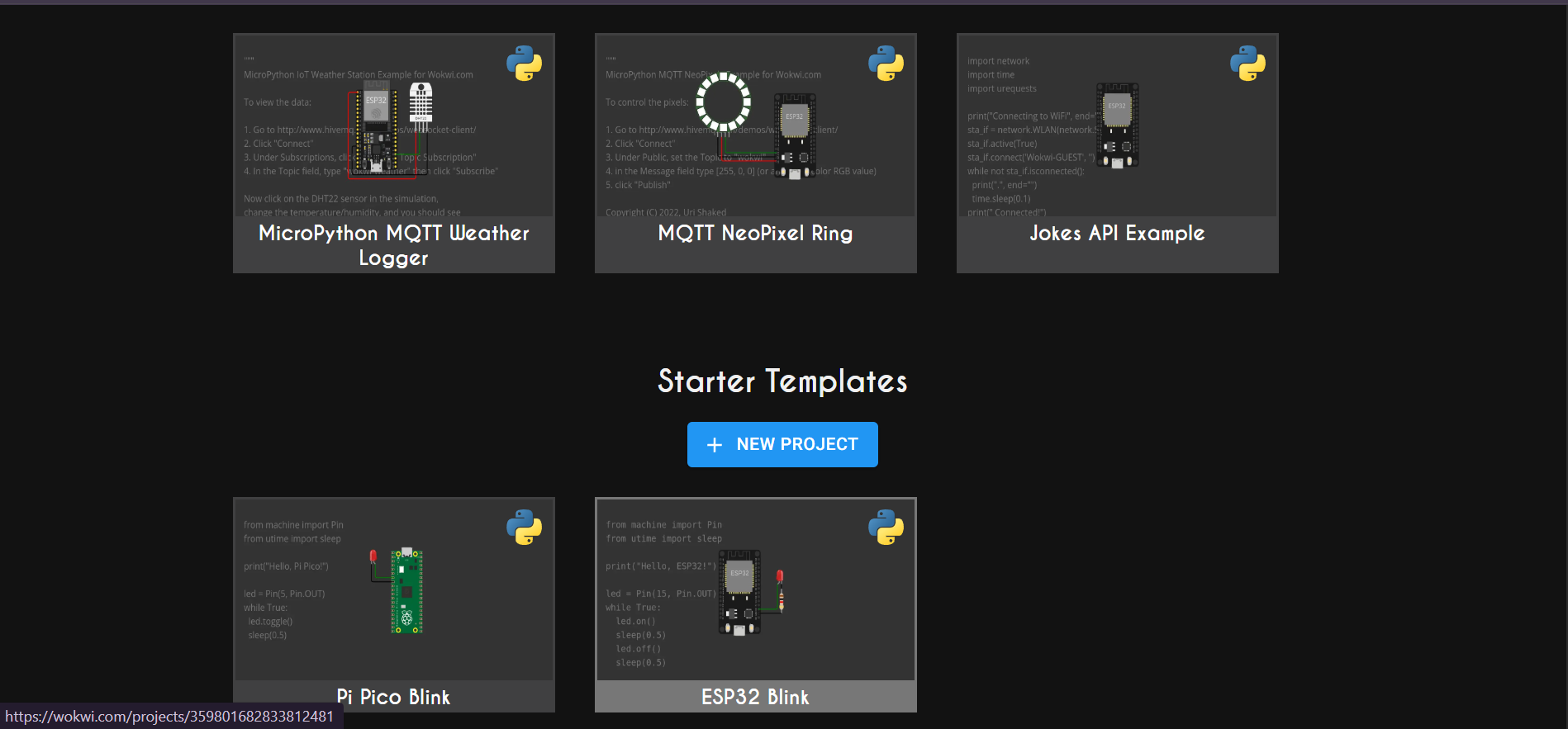
Step 4: Click on New project
Step 5: Click on “MicroPython on ESP32”
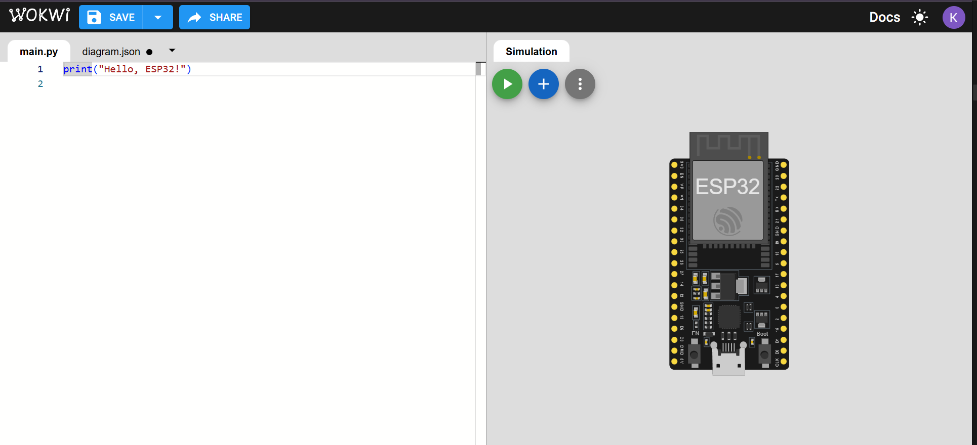
Step 6: Access the Circuits Workspace
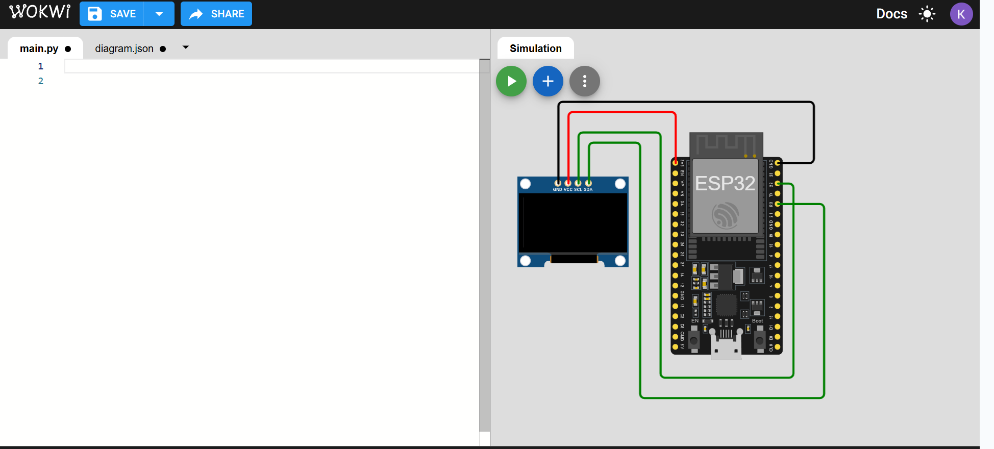
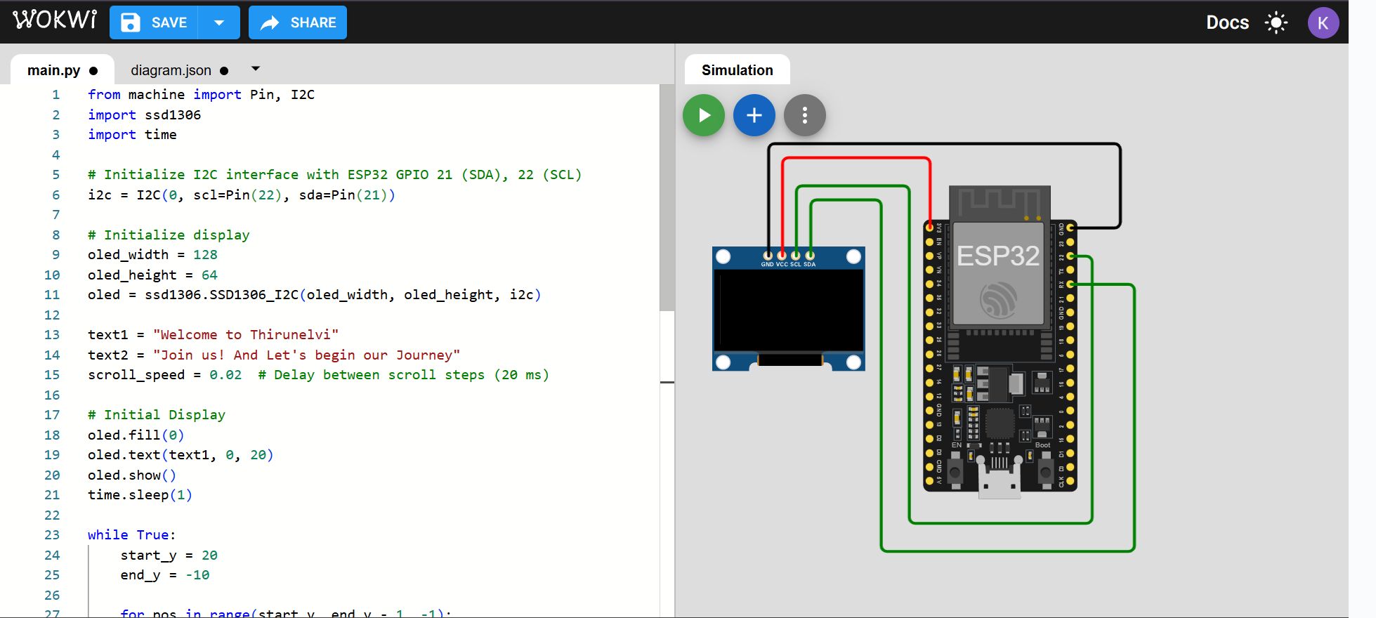
Step 7: Start Building Circuits and Add Components and Wires