- Measure the power consumption of an output device..
- Document your work on the group page and reflect what you learned on your individual page.
Individual assignments:
- Add an output device to a microcontroller board you've designed and program it to do something..
Group Assigment
we measure the power consumption of the output device using equipments.
Click on this button to get it to our Group Assignment Page
Individual Assignment
heroshot
What is Output Devices ?
Output devices in electronics are components that convert electrical signals or digital data into a form that humans can perceive or use.
They play a crucial role in displaying, producing sound, or transferring data from a system to the external environment. These devices can convert data into visual, auditory, or physical forms. The primary function is to present the results of data processing to users.
They are essential for interaction with the system, providing feedback or information in real-time. Output devices can vary in size, function, and technology used. Their effectiveness directly influences user experience and system usability.
Actuators
actuator is a device that converts an electrical signal or another form of energy into a physical action or mechanical movement.
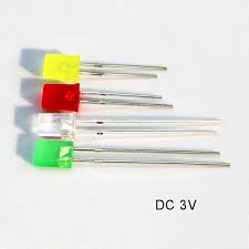
1. LED
A light-emitting diode (LED) is a semiconductor device that emits light when an electric current flows through it. When current passes through an LED, the electrons recombine with holes emitting light in the process.
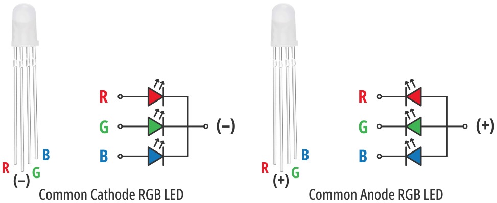
2. RGB LEDr
An RGB LED is a type of light-emitting diode that can produce a wide range of colors by combining red, green, and blue light. It essentially contains three separate LEDs (red, green, and blue) within a single package. By adjusting the intensity of each color, RGB LEDs can create millions of different hues, including white light.
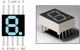
3. 7 Segment Display
A 7-segment display is a common electronic display component used to show numerical digits and some letters. It consists of seven LEDs arranged in a specific configuration, resembling the number "8" with three horizontal segments and four vertical segments.
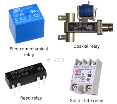
4. relays
relay is an electrically operated switch used to control larger circuits with a smaller, lower-power signal. It acts as a bridge, allowing low-current signals to switch high-current loads.
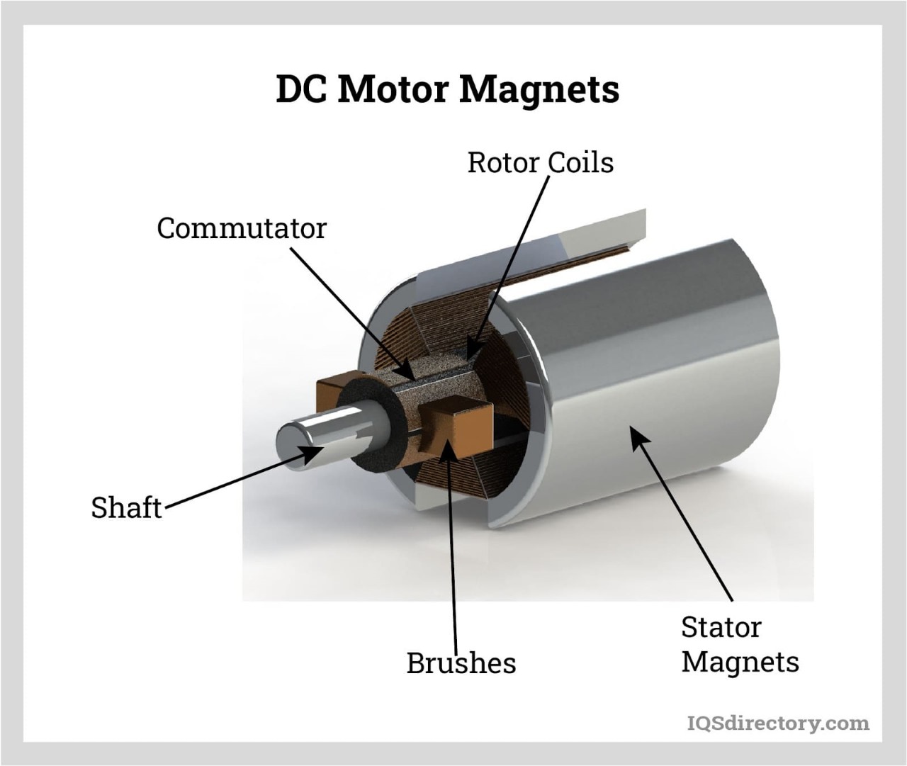
5. DC Motor
A DC motor is an electrical machine that converts electrical energy, specifically direct current (DC), into mechanical energy, typically rotational movement. It works by using magnetic forces generated by the current flowing through coils to produce a torque, causing the motor to rotate.
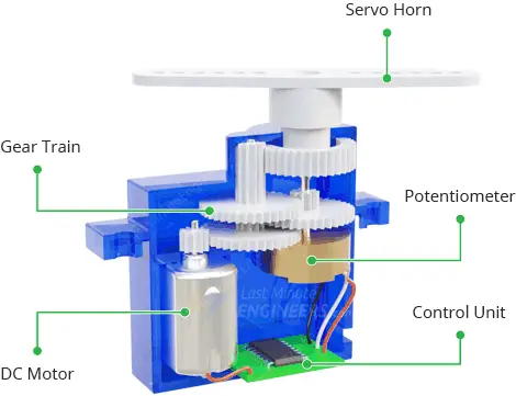
6. Servo Motor
A servo motor is an electrical motor that allows for precise control of angular or linear position, speed, and torque using a feedback loop system. It uses a feedback mechanism to accurately control its motion, ensuring it moves to and stops at the specified position.
7. Stepper Motor
A stepper motor is a brushless DC electric motor that converts digital pulses into incremental shaft rotation. Unlike traditional DC motors that rotate continuously, stepper motors move in discrete steps, each corresponding to a specific angle of rotation (often 1.8 degrees for a typical motor), allowing for precise control over speed, position, and torque.
8. Buzzer
A buzzer or beeper is an audio signaling device, which may be mechanical, electromechanical, or piezoelectric (piezo for short). Typical uses of buzzers and beepers include alarm devices, timers, train and confirmation of user input such as a mouse click or keystroke.
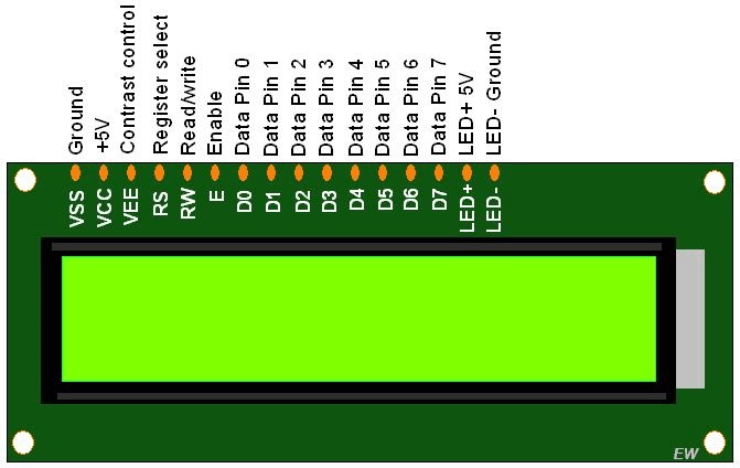
9. LCD Display
An LCD consists of a layer of liquid crystals sandwiched between two transparent electrodes. When an electric current is applied, the crystals align to control the amount of light passing through them, creating the image you see on the screen.
10. OLED Display
An Organic Light-Emitting Diode (OLED) is a type of display technology where light is generated by organic materials. Unlike traditional LCDs, OLEDs don't use a backlight, meaning each pixel emits its own light, resulting in high contrast, deep blacks, and wide viewing angles.
Line Items
These are the Line Items that i have been used to create these design.
- Seeed studio Xiao ESP32C3 module X 1
- SMD LED (1206) X 1
- SMD resistor 100 ohms (1206) X 1
- Header Pins - 1x4 , 1x7, 1x5
- KY - 004 Tactile switch X 1
- Joystick Module X 1
- 0.96 inch OLED Display X 1
Preparaing the Board
I have used KIcad Software to Create adn Develop my PCB Board
I created the Schematic and PCb Design with XIao ESP32C3 Microcontroller for my final Project as Well.
Here is my pcb design of my PCB Board that i created on it.
Here is the 3d Viewer of my design that i made on it.
PCB Production
I have Used FlatCAM software to Convert the gerber files to G-Code on it and here is the Gerber image of it
BY using FlatCAM on it by creating the toolpath for it on it as well as on this.
Here is the final generation of it.
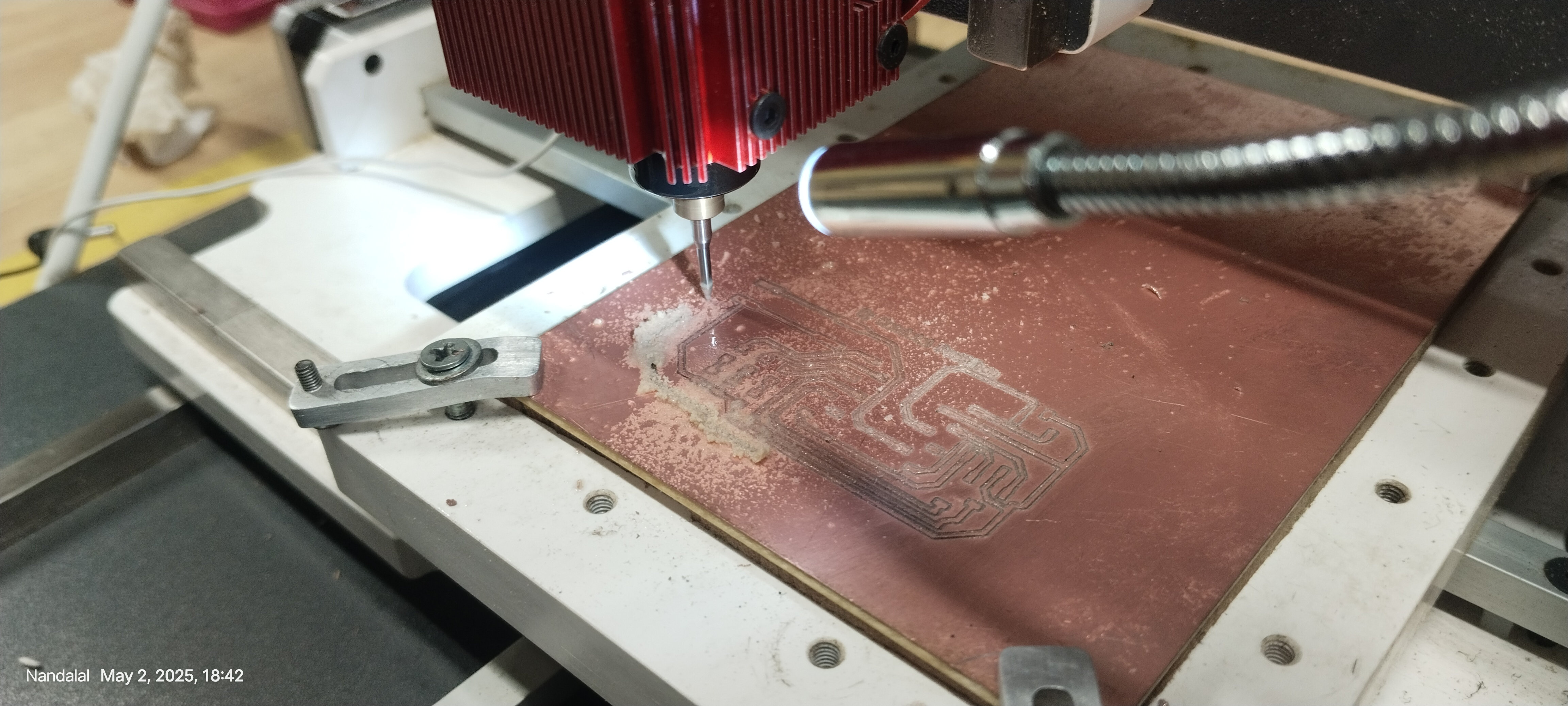
Then i have used Wegstr Software to control our PCB milling Machine to work on it and also uploading it and also on the board designing as well to cut of my Board in it.
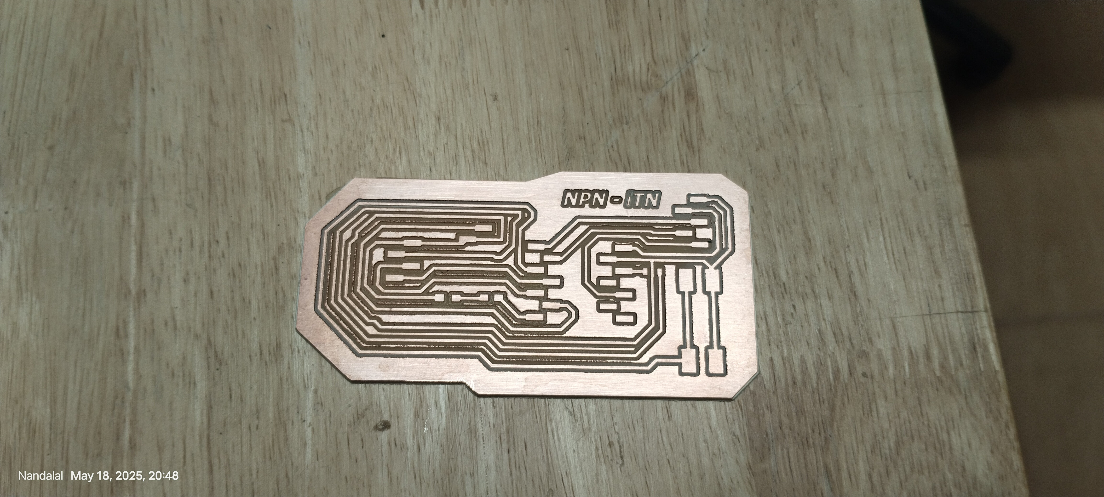
Here is the few images of my board production .
this is the board that i have made
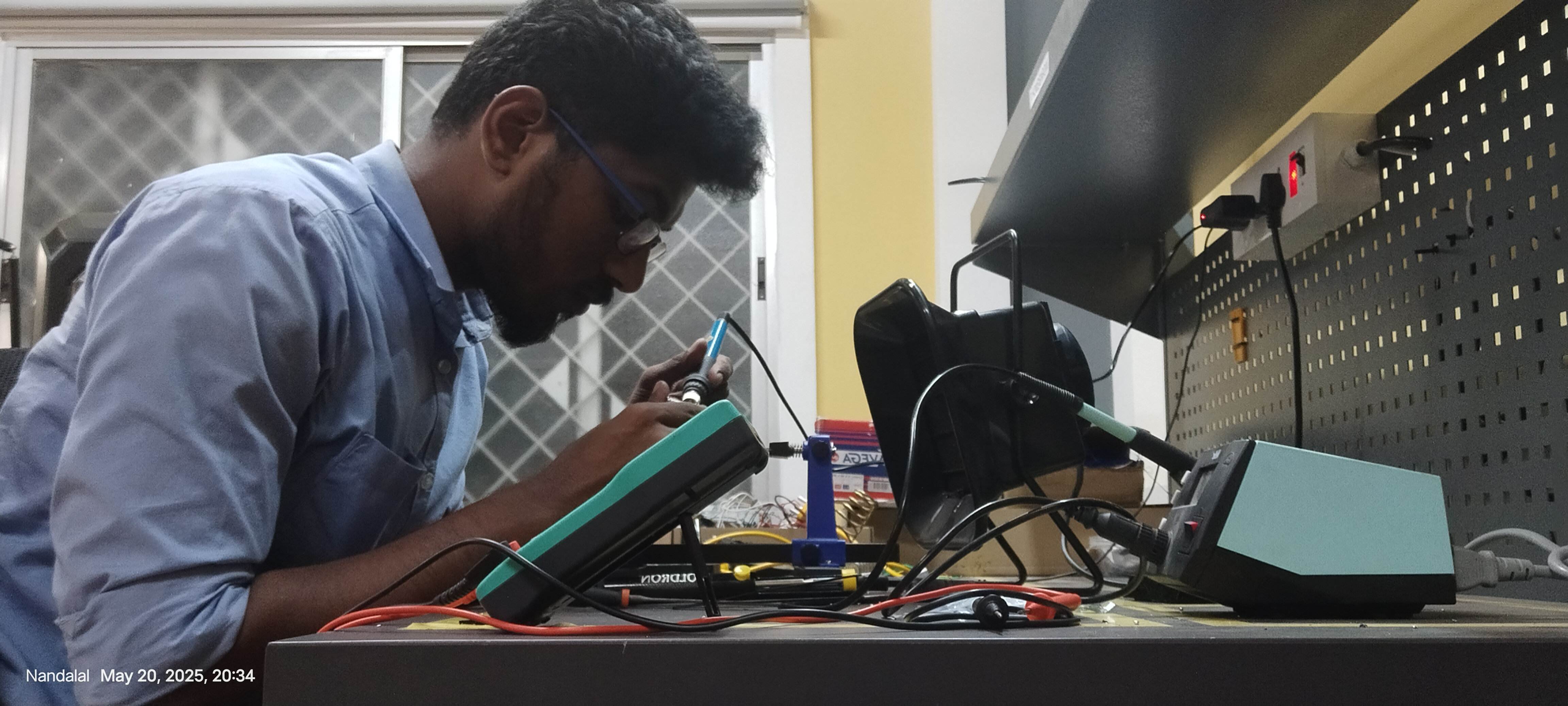
Our Global Instructor is showing us how to do proper soldering in it.
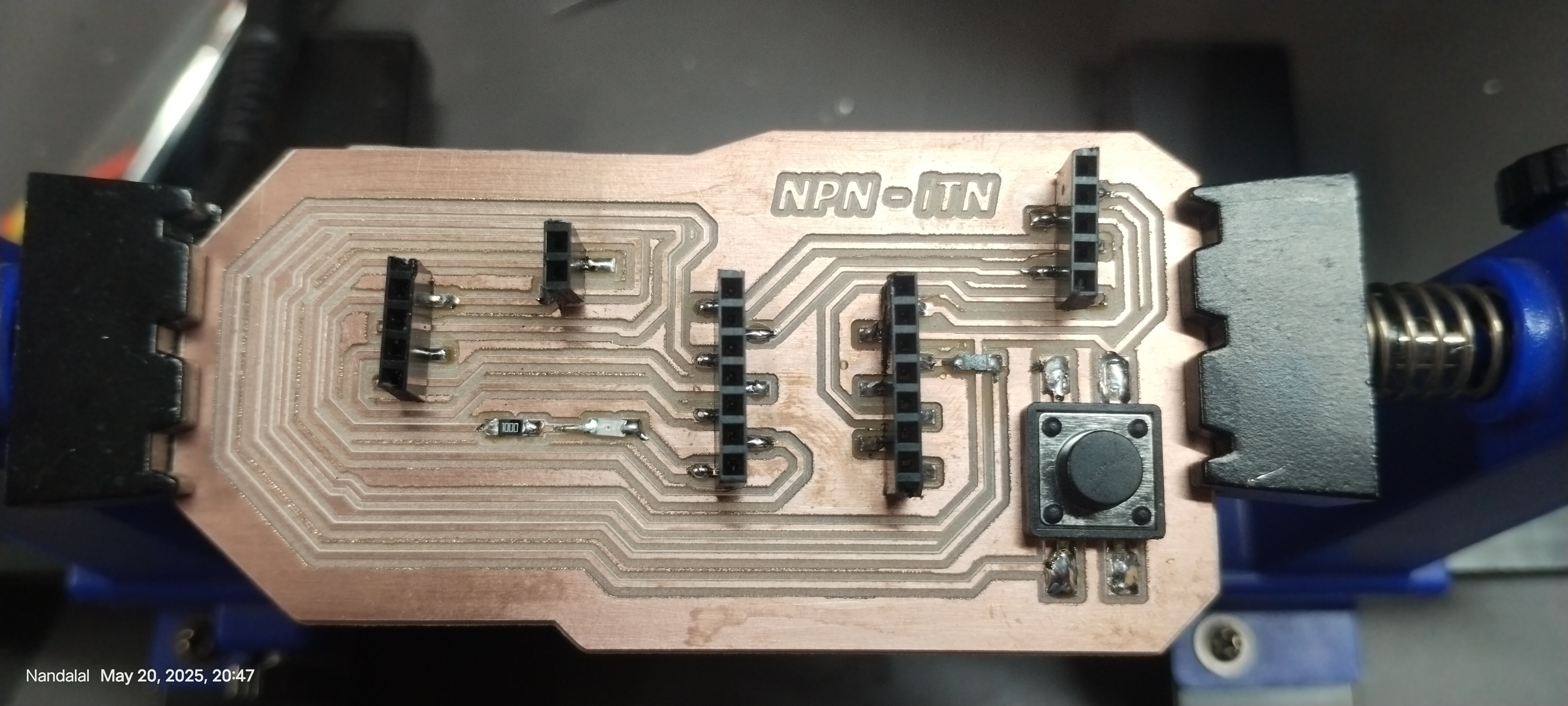
i have checked the board on it by using multimeter for continuity test and solder the components with the board.
Intregration of Display with PCB Board that is by using OLED Display
OLED Display
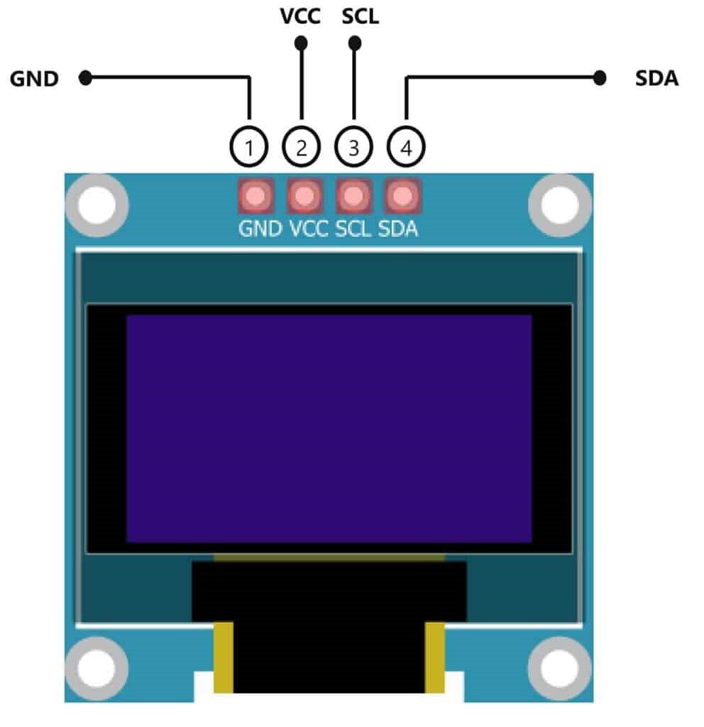
The OLED display doesn’t require backlight, which results in a very nice contrast in dark environments. Additionally, its pixels consume energy only when they are on, so the OLED display consumes less power when compared with other displays.
The model we’re using here has only four pins and communicates with the Arduino using I2C communication protocol. There are models that come with an extra RESET pin. There are also other OLED displays that communicate using SPI communication.
This is the pin diagram of the Xiao ESP32C# module to connect with OLED Display.
Pin
Wiring to Xiao ESP32C3
Vin
5V
GND
GND
SCL
A5
SDA
A4
Programming
#include
#include
#include

#define SCREEN_WIDTH 128
#define SCREEN_HEIGHT 64
#define OLED_RESET -1

Adafruit_SSD1306 display(SCREEN_WIDTH, SCREEN_HEIGHT, &Wire, OLED_RESET);

#define JOY_X A0
#define FIRE_BTN 2

int shipX = SCREEN_WIDTH / 2;
const int shipY = SCREEN_HEIGHT - 10;

bool bulletActive = false;
int bulletX, bulletY;

int enemyX = 10;
int enemyY = 0;
int enemySpeed = 1;

int centerX = 0;          // Joystick resting X position
const int deadZone = 20;  // Dead zone range

int score = 0;            // Count of enemies shot

void drawAircraft(int x, int y) {
  // Draw a simple aircraft pointing up
  // x,y is bottom center of the aircraft

  // Body: vertical line
  display.drawLine(x, y, x, y - 7, SSD1306_WHITE);

  // Wings: diagonal lines
  display.drawLine(x, y - 3, x - 4, y - 1, SSD1306_WHITE);
  display.drawLine(x, y - 3, x + 4, y - 1, SSD1306_WHITE);

  // Tail: horizontal line at bottom
  display.drawLine(x - 2, y, x + 2, y, SSD1306_WHITE);

  // Nose: filled triangle on top
  display.fillTriangle(x - 1, y - 7, x + 1, y - 7, x, y - 10, SSD1306_WHITE);
}

void setup() {
  Serial.begin(115200);
  pinMode(FIRE_BTN, INPUT_PULLUP);

  if (!display.begin(SSD1306_SWITCHCAPVCC, 0x3C)) {
    Serial.println("SSD1306 init failed");
    while (true);
  }
  display.clearDisplay();
  display.display();

  // Calibrate joystick center by averaging multiple readings
  long sum = 0;
  const int samples = 20;
  for (int i = 0; i < samples; i++) {
    sum += analogRead(JOY_X);
    delay(10);
  }
  centerX = sum / samples;
  Serial.print("Calibrated joystick center X: ");
  Serial.println(centerX);

  Serial.println("Setup done");
}

void loop() {
  display.clearDisplay();

  int xVal = analogRead(JOY_X);
  Serial.print("Joystick X: ");
  Serial.println(xVal);

  if (xVal < centerX - deadZone) {
    shipX -= 2;
  } else if (xVal > centerX + deadZone) {
    shipX += 2;
  }
  // else no movement

  shipX = constrain(shipX, 0, SCREEN_WIDTH - 10);

  if (digitalRead(FIRE_BTN) == LOW && !bulletActive) {
    bulletActive = true;
    bulletX = shipX + 5;
    bulletY = shipY;
  }

  if (bulletActive) {
    bulletY -= 5;
    if (bulletY < 0) bulletActive = false;
  }

  enemyY += enemySpeed;
  if (enemyY > SCREEN_HEIGHT) {
    enemyY = 0;
    enemyX = random(0, SCREEN_WIDTH - 10);
  }

  // Check collision between bullet and enemy
  if (bulletActive &&
      bulletX >= enemyX && bulletX <= enemyX + 10 &&
      bulletY >= enemyY && bulletY <= enemyY + 10) {
    bulletActive = false;
    enemyY = 0;
    enemyX = random(0, SCREEN_WIDTH - 10);
    score++;  // Increase score on hit
  }

  // Draw ship as aircraft
  drawAircraft(shipX + 5, shipY + 5);

  if (bulletActive) display.drawPixel(bulletX, bulletY, SSD1306_WHITE);

  // Draw enemy as rectangle
  display.fillRect(enemyX, enemyY, 10, 5, SSD1306_WHITE);

  // Display score top right
  display.setTextSize(1);
  display.setTextColor(SSD1306_WHITE);
  display.setCursor(SCREEN_WIDTH - 50, 0);
  display.print(F("Score: "));
  display.print(score);

  display.display();
  delay(50);
}
- I connected the IR sensor analog pin with XIAO ESP32S3 board’s A2 pin, and also connected the 5V and GND with the Microcontroller.
- To check this I connected one LED in the microcontroller, I set the +Ve with D4 and connected the GND in that board.
- Then I set the IR sensor as input and LED as output, and give the serial begin 115200.
- I wrote the code like whenever I keep any object near by IR sensor then the LED will blink, remaining time it only as off condition.
Testing
there has been some miscaluclation that i made that is i have not given enough space for the joystick to move. so i was unable to mave that well
So i have used jumper cable to connect the joystick module in order to move that freely.
Download Files
Here, you can download the files that i made over this assignment