What does it do?
This device functions as a pest counting system, primarily designed to estimate insect population proxies rather than trapping insects to diminish their populations. This data empowers users to make informed decisions regarding pest control applications, whether chemical or biological.
Ancillary functions include measuring degree days. This feature allows for the prediction of new adult insect generation emergence, using the date of a control application as a reference point. Temperature is measured by a DHT11 sensor.
The system operates with a camera directed at a sticky tape to capture images of caught insects. A led is turn on when a picture is taken in order to illuminate the tape, whenever light is insufficient. These images are then sent to a computer via a server for insect detection and tallying. The computer also displays the estimated degree days. A mechanical component with buttons facilitates the loading of a sticky tape roll, which automatically renews at set intervals. The sensor structure is operated by using a 9V battery. The current is used directly for the motor and converted to 5V to feed a Xiao ESP32 S3 sense.
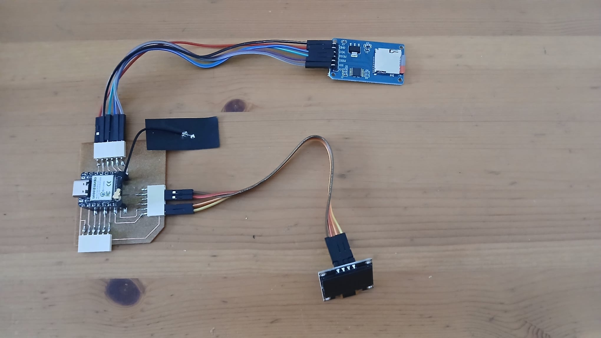
The aforementioned server contains a Xiao ESP32 S3 (not sense version) a SD card to store images and temperature data until the time when a local computer connects to download the data through a Shiny dashboard.
There are several academic projects similar to this one. Additionally, there is a comparable commercial project, as well as a related initiative developed during the Fab Academy 2020.
The primary differentiator of this project is its automated sticky card changer, powered by a motor and a roll of tape.
What has been designed:
Electronics
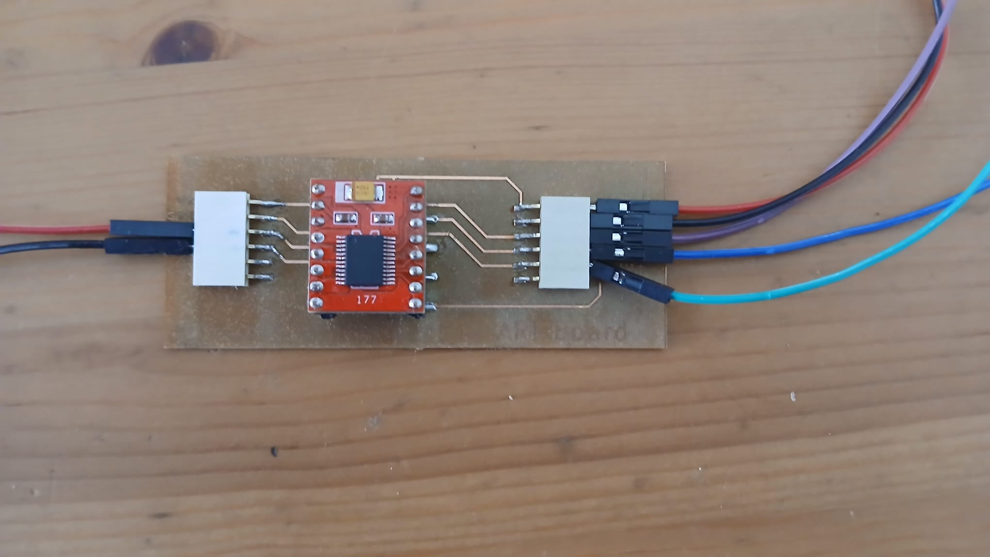
For the project I designed 4 PCB’s:
- Control PCB: integrates all the other PCBS
- Motor H Bridge PCB
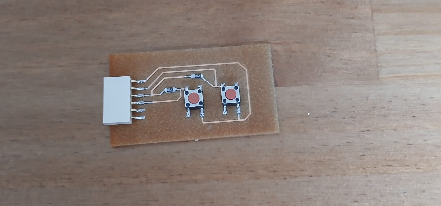
- Button PCB
- Server PCB
- Power station PCB
Below you can find Four of the 5 PCB’s made for this project.
CAD
Three housing structures were designed in Fusion 360
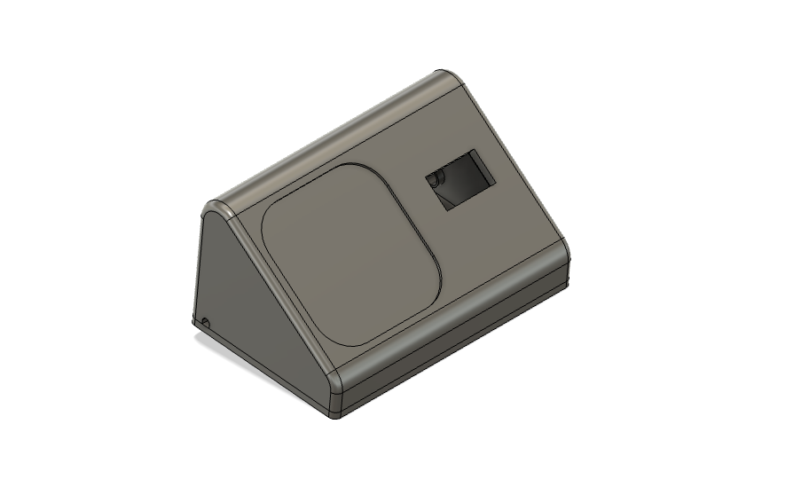
- Body case and roof including tape mounting structures.
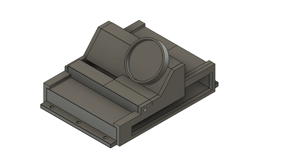
- A control case to house the control board, its camera and a led.
- A server case to house a PCB, an SD card and a Oled screen.
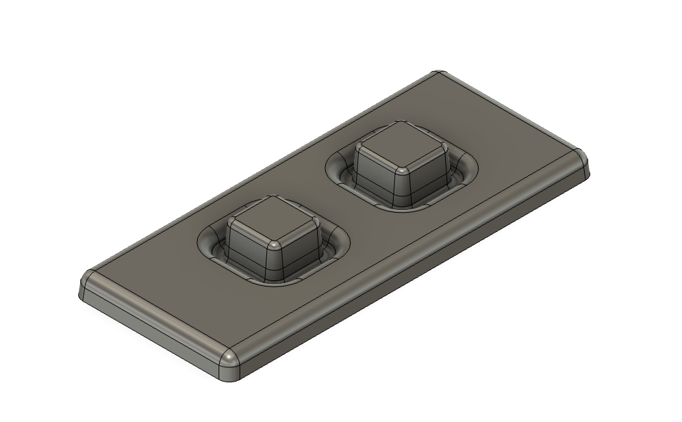
- A model of silicon buttons.
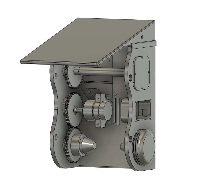
Mechanics/mounting
I designed a gear system to enable rolling and unrolling the tape back onto its original cylinder. This system consists of a movable platform on which the motor is mounted which interacts with the gears of two tape holders.
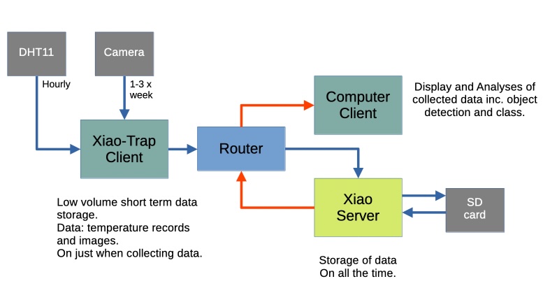
Networking System
The networking system is characterized by three actions:
Sensor to Server: This involves the code responsible for transmitting image and temperature data from the sensor to the central server.
Sensor Data Reception and Storage: This component handles receiving temperature and image data from the sensor and storing it directly onto an SD card.
Server to Local Computer: This outlines the code used to send sensor data from the server to a local computer for further analysis or display.
Below you can find an schematic of the networking system:
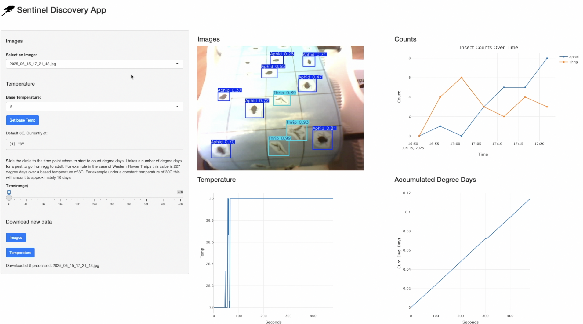
Interphase
I designed a user interphase in Shiny(R) that:
- Downloads the images from the server,
- Displays the images taken,
- Connects with python to use YOLO in order to detect and count insects
- Estimates degree days to predict when the next adult generation will emerge based on data gathered by the DHT11.
Sensor actuation code
The actuation system was designed primarily for testing purposes. For actual deployment, the current parameters should be replaced with values optimized for real-world performance. Below is a pseudocode example illustrating the basic logic of the actuation:
Main loop
conditional statement for motor response upon pressing buttons. Temperature reading.
- Time condition 1.
- Led On
- Photo shoot
- Led Off
- Motor forward
- Motor stop
- Send data to server
- Time condition 2.
- Send Temperature Data
Materials used
Below is a Bill of Materials (BOM) detailing all the components used in the project. Each item includes a link to its corresponding product page. The total cost for the entire system—including both the server and the camera trap—is approximately € 111. Most components were sourced from Amazon, Digikey and AliExpress, with the exception of the tape roll, which was purchased from Econex.
Processes used in the development of the product.
Design & Modeling:
PCB: Circuit board layouts were designed using KiCad.
Mechanical Components: The housing and tape-handling mechanism were modeled in Fusion 360.
Manufacturing & Fabrication:
Additive (3D Printing): All housing components were 3D printed on Bambu Lab A1 and A1 Mini printers.
Subtractive (Milling & Engraving):
A wax block was milled to create a casting mold for the silicone buttons.
PCBs were cut to shape with a Lunyee 500W CNC router.
Circuit tracks were engraved onto the boards using a ComMaker B4 MOPA 60 laser.
Firmware:
- The core software for motor actuation and network communication was developed entirely in MicroPython.
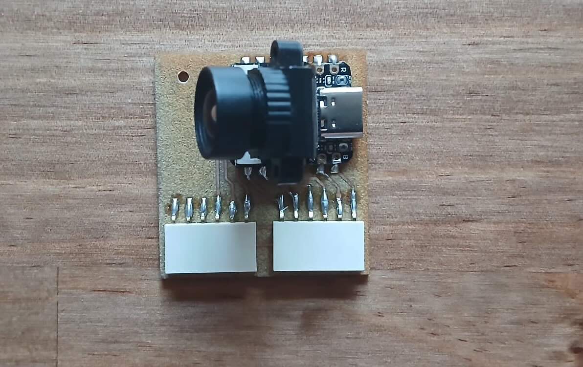
Challenges overcomed
Initially, the images obtained by the original camera (OV2640) that came with the Xiao S3 sense were low in light and covered a small area of the tape. To overcome this, I searched for a camera in the same family with a wider field of view, which can be found in the BOM. Another challenge was choosing a mechanism that allowed the user to rewind the tape to its original cardboard cylinder. For this, I used a lever to switch the motor gear from one gear to another. See video below. One last challenge I faced was the wireless transfer of information between the devices. The transmission was highly erratic between the Xiao MCUs. Eventually, this problem was solved by the use of antennas.
Testing and evaluation of product
An important criterion was ensuring the tape is easy to change. This was achieved by including a door that allows removal of the upper tape holder.
The product performed well mechanically; you can see a fast forward video of the rolling process over nearly an hour.
The device could be improved by adding guides to restrict the position of the sticky tape.
Finally, image transmission/quality is functional, but the quality could still be improved to better capture the small size of greenhouse insects. Below you can see an accompanying video that shows the download of the pictures taken in the video above. Not that the pictures are upside down!
Implications
The product provides an additional level of automation compared to other camera trap devices, specifically through the automatic changing of sticky trap cards. Ideally, this reduces the labor required for insect monitoring. Such devices are important as they enable more efficient insecticide applications by estimating proxies for population densities or tracking the presence of pests on crops. These actions can help reduce pesticide resistance and application costs.
Licensing
At this stage, I am uncertain which intellectual property route to pursue. This decision will depend on the level of interest in the device and its potential market. Depending on these factors, I would either apply for a patent or, if the goal shifts toward open development, opt for a Creative Commons license.
Quick Log of FabAcademy Weeks Contributing to My Final Project
I’m quite pleased with the progress of my project. I was fortunate to find tasks that aligned well with its development, which made the process more efficient and rewarding.
The initial CAD design was completed this week. I began considering how the roll would be mounted, identifying potential challenges and exploring ways to simplify the mounting process to ensure it is not overly difficult or time-consuming.
Some camera testing was conducted this week. References to relevant sections of the code can be found here. Additionally, I discovered a valuable resource—TechToTinker—which contains numerous helpful examples and insights that proved useful in the development of my project.
Some progress was made on designing and 3D printing a tape roll holder. The coneshape form was adopted.
I began exploring potential methods for controlling a DC motor and reading data from a DHT11 sensor. Several useful references supported this work, particularly resources from DroneBot Workshop, which provided valuable insights and practical examples.
This week, I conducted tests with both the camera and the DHT11 sensor.
For this week, I focused on testing the half-bridge driver, OLED displays, and SD cards. I also designed the respective PCBs for each component.
This week included some prototype code for communication between the Xiao and the local computer. Like much of the project code, it was developed through a combination of online examples, personal intuition/coding skills, and a good amount of assistance from large language models (LLMs) for debugging and generating short code snippets. Although I was initially hesitant to use LLMs, I eventually found that they significantly improved my efficiency.
I cast the silicone buttons used in the button PCB and also designed and fabricated the corresponding PCB.
During this week, the proto code for the Shiny interface was developed
This week was primarily focused on planning and organizing the wiring for the project.
This week laid the foundation for image classification of aphids and thrips using YOLO. Most of the code implemented in the Shiny app for this functionality can be traced back to work done during this period.
Files
Note: For the coding files, I relied on a combination of online resources, my background knowledge, and large language models (LLMs) to develop functions for specific tasks and to debug issues. The online resources referenced can be found in the assignment weeks, and sample prompts used with LLMs are included in the header of each file.