- group assignment:
- demonstrate and compare the tool chains and development workflows
- for available embedded architectures \(\checkmark\)
- individual assignment:
- browse through the data sheet for your micro controller \(\checkmark\)
- write a program for a micro controller, \(\checkmark\)
- and simulate its operation, \(\checkmark\)
- to interact (with local input &/or output devices) \(\checkmark\)
- and communicate (with remote wired or wireless connections) \(\checkmark\)
- extra credit: test it on a development board
- extra credit: try different languages &/or development environments
Group Assigment
The full group assigment can be found:
https://fabacademy.org/2025/labs/cuenca/generic.html#week4
For the group assignment chose the Raspberry pico and the Xiao ESP32 S3 sense.
Raspberry pi pico
Main characteristics
- Dual-core Arm Cortex-M0+ processor, flexible clock running up to 133 MHz
- 264KB of SRAM, and 2MB of on-board flash memory.
- USB 1.1 with device and host support.
- 26 × multi-function GPIO pins.
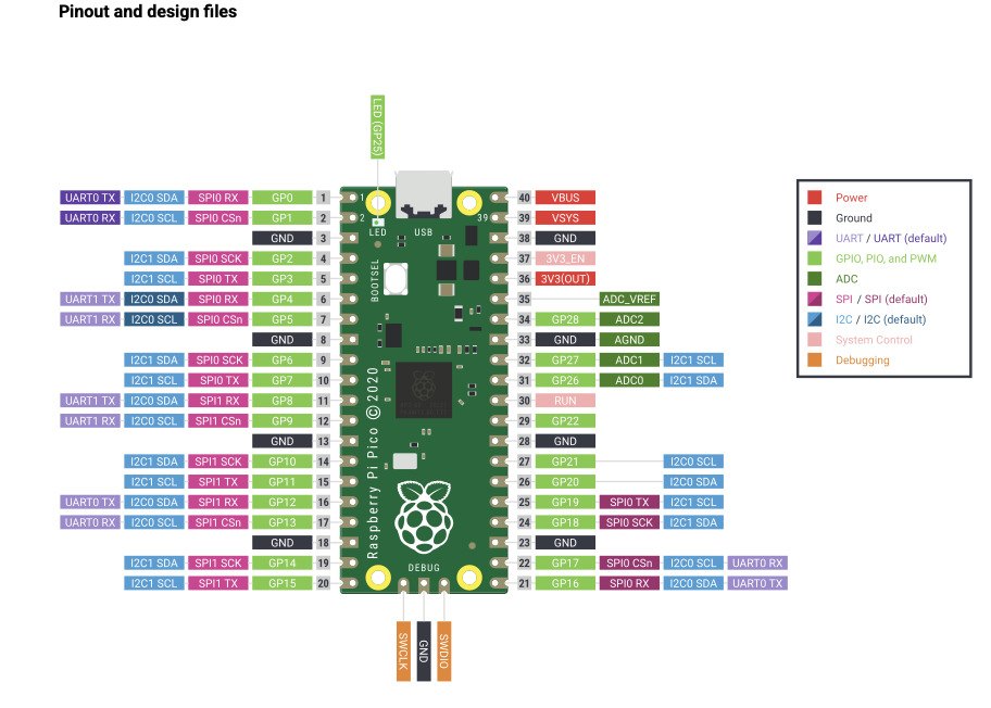
from:
“https://www.raspberrypi.com/documentation/microcontrollers/pico-series.html#pico-1-family”
For information. I looked for some terms definitions (from Wikipedia) in regards to communication:
- UART: A universal asynchronous receiver-transmitter is a peripheral device for asynchronous serial communication
- GPIO: A general-purpose input/output (GPIO) is an uncommitted digital signal pin on an integrated circuit or electronic circuit (e.g. MCUs/MPUs) board which may be used as an input or output, or both,
- ADC: Analog-to-digital converter is a system that converts an analog signal into a digital signal.
- SPI: is a de facto standard (with many variants) for synchronous serial communication, used primarily in embedded systems for short-distance wired communication between integrated circuits.
Also, Mickael recommended this video in order to understand signal communication between two boards. It nicely explained parallel and serial communication as well as synchronous and asynchronous modes and some examples of this communication modes.
https://www.youtube.com/watch?v=IyGwvGzrqp8&t=329s
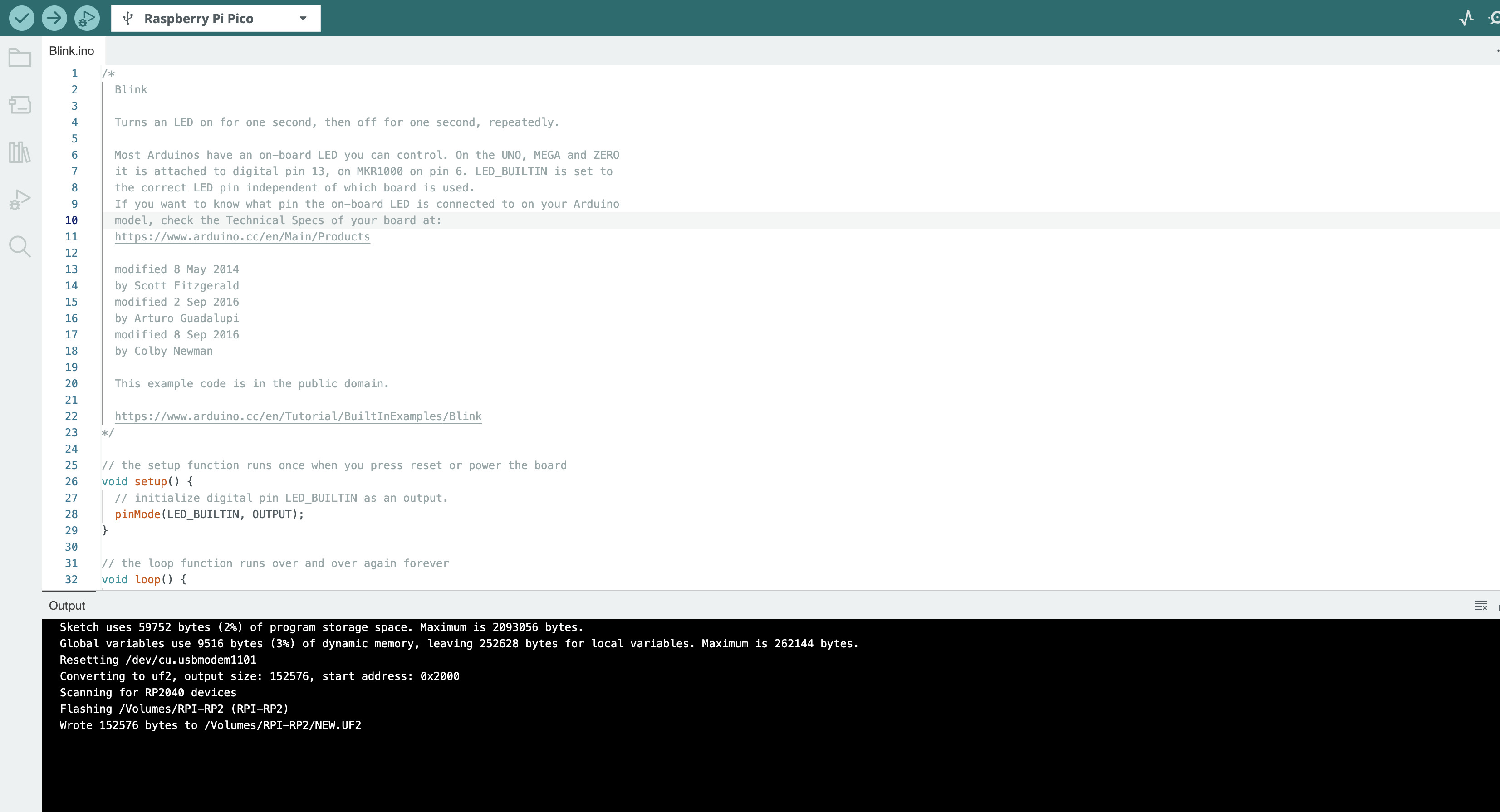
For testing I used Arduino IDE and included a blink led code in C++ from the basic scripts Arduino provides.
Xiao ESP32 S3
The Xiao ESP32 S3 sense is a powerful little (21 x 17.8mm) micro
controller.
Below, a link is provided with some general specifications:
https://wiki.seeedstudio.com/xiao_esp32s3_getting_started/
Some of the characteristics from this page to point out are:
- Xtensa LX7 dual-core, 32-bit processor that operates at up to 240 MHz
- 11 + 2 GPIO pins.
- Complete 2.4GHz Wi-Fi subsystem and.BLE: Bluetooth 5.0, Bluetooth mesh
- OV2640 camera
- Microphone
- On-chip 8M PSRAM & 8MB Flash
- SD card slot for external 32GB FAT memory
- USB-C enabled
- Average power consumption: 5V
- Working temperature: 40°C ~ 65°C
Some diagrams for the ESP32S3 sense follow.
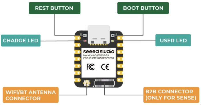
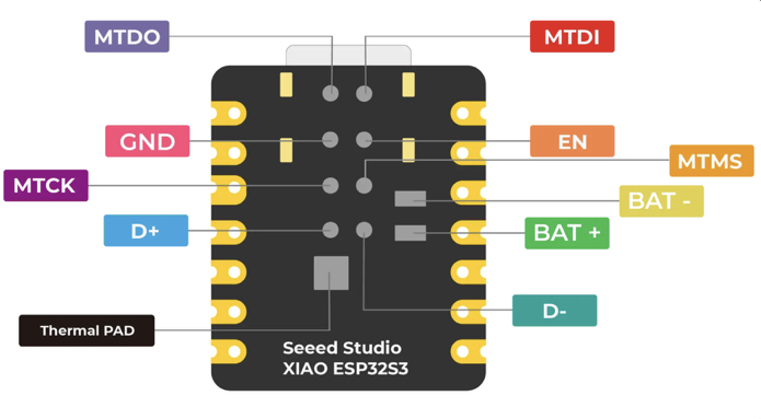
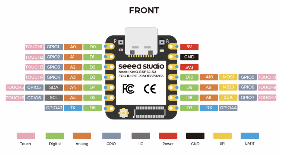
A more detailed schema of the board can be found below:
https://files.seeedstudio.com/wiki/SeeedStudio-XIAO-ESP32S3/res/XIAO_ESP32S3_ExpBoard_v1.0_SCH.pdf
In case you are looking for the user led for this model, thanks to Pablo from FL Leon I went to look harder for this. You can find it in diagram below.
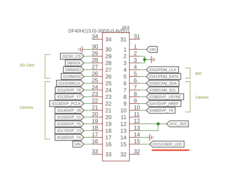
Another well documented page for this controller developed by the DroneBot Workshop is provided below.
https://dronebotworkshop.com/xiao-esp32s3-sense/
For more detail one can look at the data sheet
https://files.seeedstudio.com/wiki/SeeedStudio-XIAO-ESP32S3/res/esp32-s3_datasheet.pdf
For example here you can find details on the power management unit, the type of Serial Peripheral inter phase available and information on weak pull up and down resistors.
And finally, I found this micro controller in AliExpress for 15.99 euros so it quite affordable.
Testing
As I had already used C++ through the Arduino IDE for this week I
wanted to use something different.
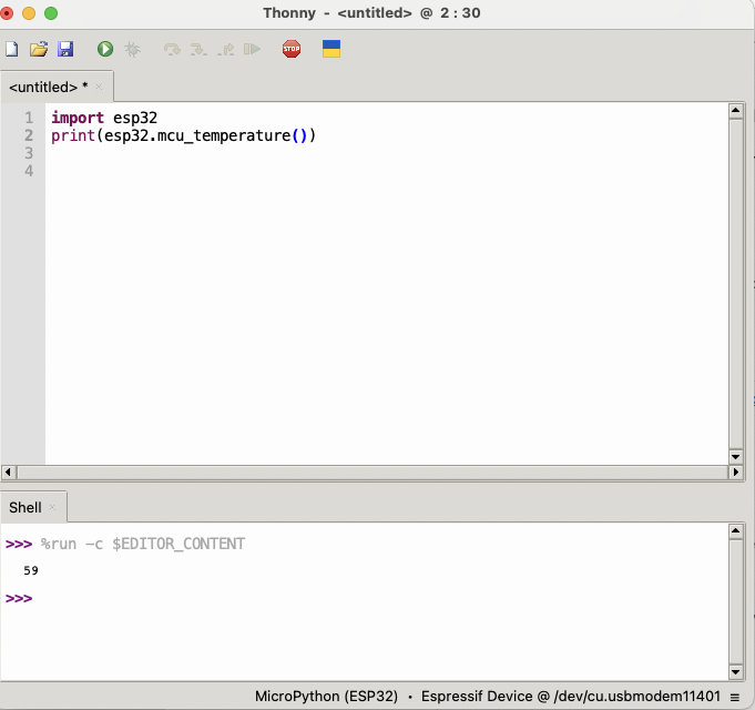
For this, I installed the IDE Thonny and uploaded the firmware to the
board, you can see the documentation for this in my individual
assignment if you need it. The library esp32 has the function
mcu_temperature() that allows you measure the board
temperature.
As you can see you can run interactively python command in the console of Thonny.
And I also tested a blink the user led program using pin 21. For reference, note that for the Xiao pin # is GPIO #.
from machine import Pin
from time import sleep
led_pin = 21
led = Pin(led_pin, Pin.OUT)
for i in range(10):
  led.on()
  sleep(1)
  led.off()
  sleep(1)
  print("Blink",i+1)
Note: tips from the dronebotworkshop studio (see link above):
Reloading the Bootloader: One thing I experienced a few times when programming the XIAO is that the board would occasionally refuse to accept new programming. This usually occurred after I uploaded a program that didn’t work how I wanted it to! To resolve this issue, you need to reload the bootloader. This is pretty simple, at least if you have small hands.
- Unplug the USB-C cable.
- Hold down the ultra-tiny Boot button (it has a small “B” beside it)
- Insert the USB-C cable.
- Release the button.
Individual Assigment
Camera testing – Arduino IDE (C++)
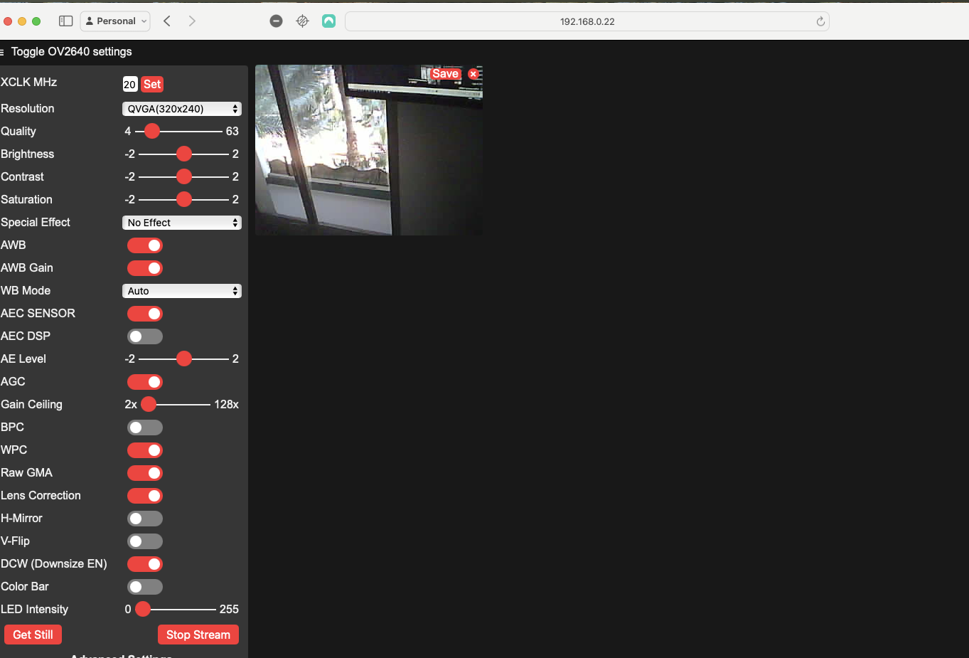
This seems to be a suitable micro controller for my project as it needs camera and WiFi capabilities. Below, I show what I had to do to get the camera working.
Steps taken:
- Identify the communication port as: /dev/cu.usbmodem11401
- Went to: Files => Examples => ESP32 => Camera webserver, and commented out: #define CAMERA_MODEL_XIAO_ESP32S3
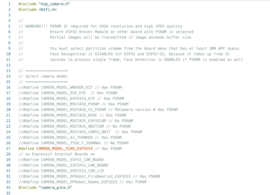
- Changed the router connection credentials i.e. the WiFi name and password in ino file above.
- Activated teh Opi PSRAM1 in the tools menu

Thereafter, I would get a hard reset message and would not work. I found
the following message in:
Bundolo Dec 2020post #22 I hope this is helpful. I googled hard reset as I was having trouble connecting my ESP8266 to the IoT. The problem would load then leave the hard reset message but all I would get was a line of …………………………. on the com window. It drove me crazy. I tried changing boards, tried changing libraries…. nothing worked!! I tried changing the baud rate down… nope…. then out of desperation I changed my network from 5Ghz to the slower rate…. bingo!!! connected fine. Then back checking I found ESP8266 doesn’t work on 5GHZ... Hope this helps some one.
Thereafter, I changed to a lower speed network and bingo it worked!
Installing Micropython
I wanted to use/test micropython for my project. Below I document its installation in the Xiao.
https://wiki.seeedstudio.com/xiao_esp32s3_with_micropython/
Download the micropython version from:
https://micropython.org/download/ESP32_GENERIC_S3/
ESP32_GENERIC_S3-20241129-v1.24.1.bin
After download, launch the Thonny IDE and then go to manage plugins and look for esptool and install it. In my case it had already been installed.
https://www.youtube.com/watch?v=GJinEfhD4Cw
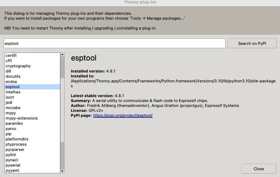
Then press Run from the menu and choose configure interpreter select interpreter as micropython (ESP32) And set Port or WebREPL to “Try to detect port automatically”
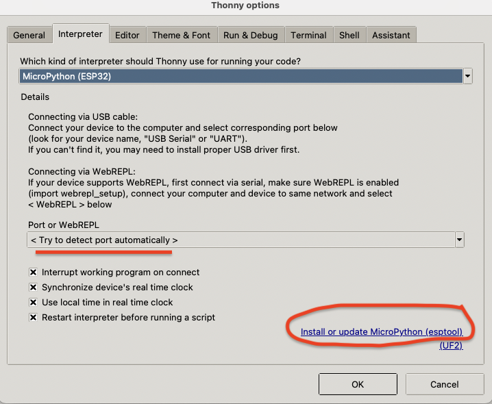
Make sure you connect the board in order to detect the port
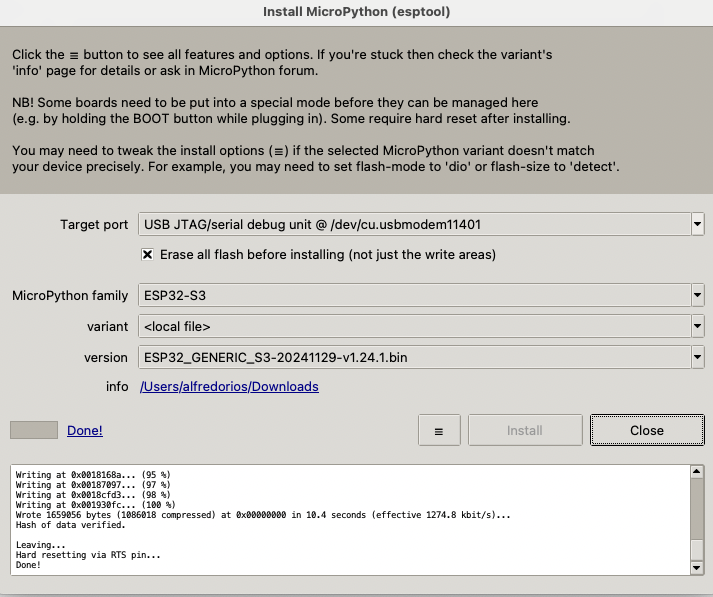 Here triple dash is used to navigate to the image
that is the *.bin file. Now you can see python in the console ran from
the micro-controller

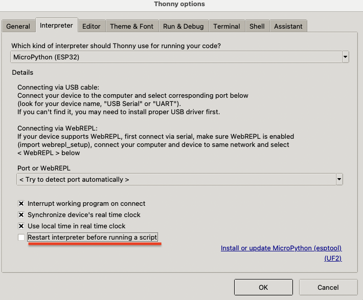
On the interpreter configuration make sure you unchecked restart the interpreter before running a script box.
Simulation
XIAO ESP32 S3
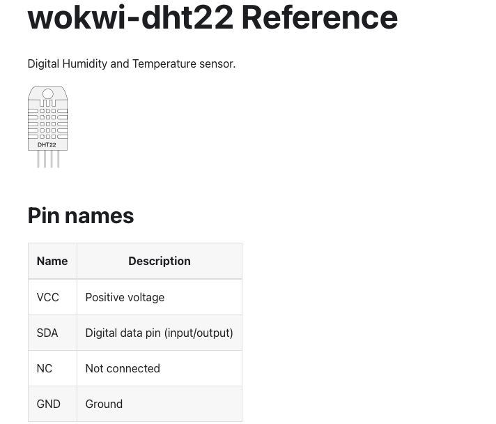
I started trying to simulate the reading of a temperature sensor DHT22 (see below). I used the following example (C++) to get started which which uses a different board (ESP32).
https://wokwi.com/projects/322410731508073042
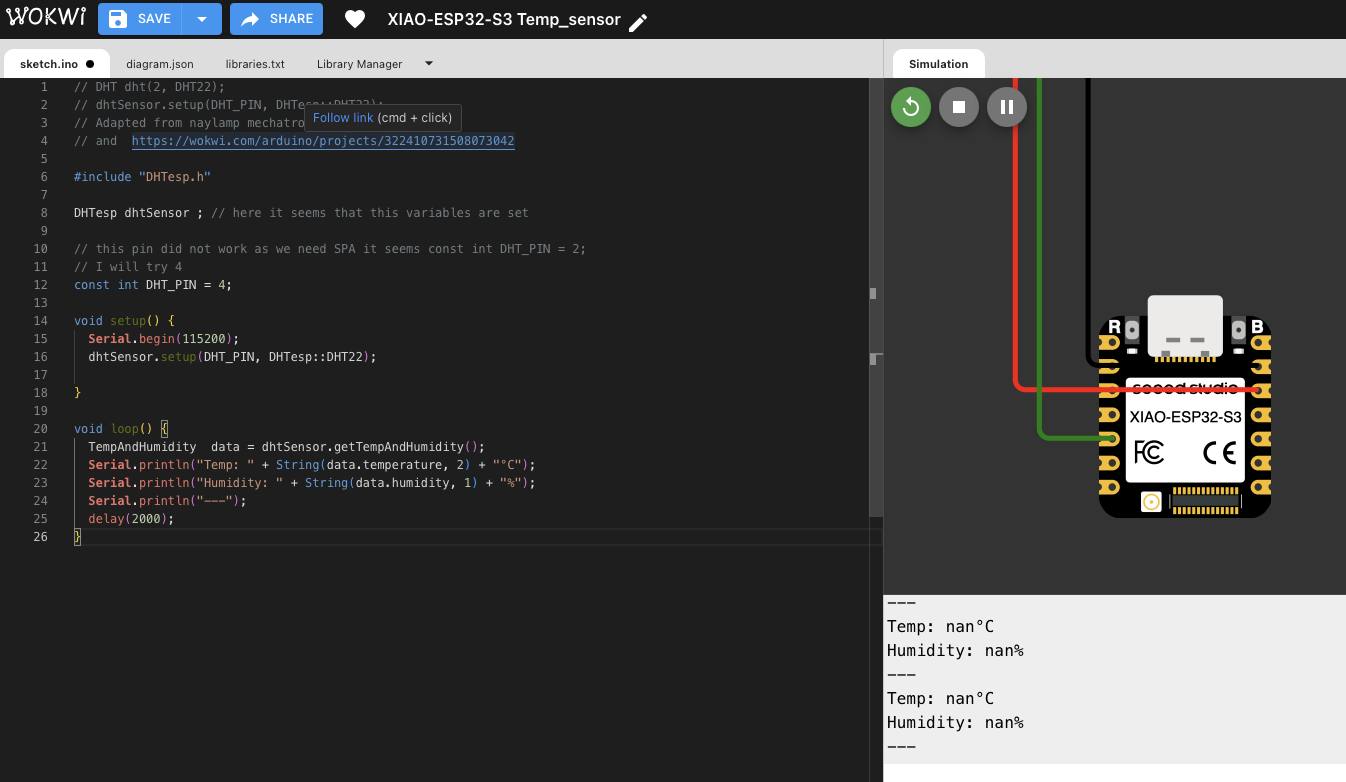
Then, I modified it for using the Xiao ESP32 template, however, I had little success. My temperature values would appear as non-available.
Thereafter, I switched to another board of the same family the STM32 using Micropython.
STM32 Python Simulation
The simulation basically uses a temperature sensor to warn the user when temperature is equal or greater than 40 degrees. Given this event a red light is flashed and a buzzer goes on. Below you can find a link and the code. You will need to change the slider from the temperature sensor to modify the temperature.
https://wokwi.com/projects/423202537587383297
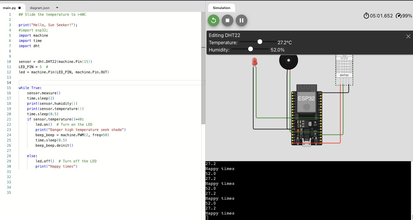
Move the slider to above 40 degrees

here is the code:
print("Hello, Sun Seeker!");
#import esp32;
import machine
import time
import dht


sensor = dht.DHT22(machine.Pin(15))
LED_PIN = 5  #
led = machine.Pin(LED_PIN, machine.Pin.OUT)

while True:
    sensor.measure()
    time.sleep(2)
    print(sensor.humidity())
    print(sensor.temperature())
    time.sleep(0.5)
    if sensor.temperature()>40:
        led.on()  # Turn on the LED
        print("Danger high temperature seek shade")
        beep_beep = machine.PWM(2, freq=50)
        time.sleep(0.5)
        beep_beep.deinit()

    else:
        led.off()  # Turn off the LED
        print("Happy times")
ESP32 server creation
For the communication part of the assignment I decided to use the internal board temperature readings and to communicate them using a website that could be accessed via a web browser by connecting to a network access point generated by the micro controller. For this, I watched this tutorial where they generated an access point using micropython.
some additional information:
https://randomnerdtutorials.com/micropython-esp32-esp8266-access-point-ap/
I modified the code to include java script tables with the following prompt in ChatGPT:
Please generate html code that with javascript will a table with two columns first one will be time second will be “MCU temperatures” and need to be populated dynamically with an array. For the time array just use the following [1,2,3,4,5].
Then, I modified the code to built a vector to replace the javscript array with a python array that was filled using the function esp32.mcu_temperature() from the esp32 module and a time stamp using the time module. Then, I embedded these arrays in the code generated by ChatGPT
Basically the code does the following:
- Creates an access point called Xiao_Server using the network library,
- listens for connections,
- triggers a response when its IP address is open,
- measures the MCU temperature and creates a time stamp,
- loads a webpage on the above IP address that has an embeded time stamp and mcu temperature strings,
- and refresh the webpage every 5 seconds.
import machine
import time
import esp32
import socket
import network
ssid = 'Xiao_Server' # access point
password = '123456789'
ap = network.WLAN(network.AP_IF)
ap.active(True)
ap.config(ssid=ssid, password=password)
while not ap.active():
pass
print('network config:', ap.ifconfig()) ## we will need this IP address
# AF_INET - use Internet Protocol v4 addresses
# SOCK_STREAM means that it is a TCP socket.
# SOCK_DGRAM means that it is a UDP socket.
s = socket.socket(socket.AF_INET, socket.SOCK_STREAM)
s.bind(('',80)) # specifies that the socket is reachable by any address the machine happens to have
s.listen(5) # max of 5 socket connections
time_vector=[] ## here I define a vector for time stamps.
mcu_temp_vector=[] ## here I define a vector of mcu temp readings
while True:
# Socket accept()
conn, addr = s.accept()
print("Got connection from %s" % str(addr))
# Socket receive()
request=conn.recv(1024)
print("")
print("")
print("Content %s" % str(request))
### here I buit a vector of the time stamps and
### a vector for the MCU temperature
### I also corrected to add a zero when minutes or seconds were less than 9.
correction_m = ""
if time.gmtime(time.time())[4] < 9:
correction_m = "0"
correction_s = ""
if time.gmtime(time.time())[5] < 9:
correction_s = "0"
time_string= str(time.gmtime(time.time())[3])+":"+correction_m+str(time.gmtime(time.time())[4])+":"+correction_s+str(time.gmtime(time.time())[5])
time_vector = time_vector + [time_string]
mcu_temp_vector = mcu_temp_vector + [esp32.mcu_temperature()]
### Below is a ChatGPT code where I asked to generate some js dyanmic tables
### I modified it as to have a vector of temperature measurments.
response = """
<!DOCTYPE html>
<html lang="en">
<head>
<meta charset="UTF-8">
<meta http-equiv="refresh" content="5" />
<meta name="viewport" content="width=device-width, initial-scale=1.0">
<title>MCU Temperatures</title>
<style>
table {
width: 50%;
border-collapse: collapse;
margin: 20px 0;
}
th, td {
border: 1px solid black;
padding: 8px;
text-align: center;
}
th {
background-color: #f2f2f2;
}
</style>
</head>
<body>
<h2>MCU Temperature Data</h2>
<table id="tempTable">
<thead>
<tr>
<th>Time</th>
<th>MCU Temperature (°C)</th>
</tr>
</thead>
<tbody>
</tbody>
</table>
<script>
const timeArray = """ + str(time_vector) + """;
const temperatureArray = """ +str(mcu_temp_vector) + """ ;
function populateTable() {
const tableBody = document.querySelector("#tempTable tbody");
for (let i = 0; i < timeArray.length; i++) {
let row = document.createElement("tr");
let timeCell = document.createElement("td");
timeCell.textContent = timeArray[i];
let tempCell = document.createElement("td");
tempCell.textContent = temperatureArray[i];
row.appendChild(timeCell);
row.appendChild(tempCell);
tableBody.appendChild(row);
}
}
populateTable();
</script>
</body>
</html>"""
conn.send('HTTP/1.1 200 OK\n')
conn.send('Content-Type: text/html\n')
conn.send('Connection: close\n\n')
conn.sendall(response)
# Socket close()
conn.close()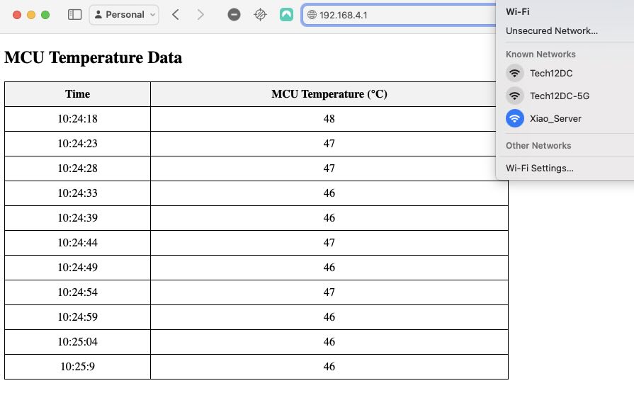
Below you can find a link to the final project development page for this week: link
Some Key Points from this week:
- Its a good idea to read data sheets as it provides use with key information for example in regards to board pins as not not all pins carry the same functions.
- It was interesting to see that you can simulate electronics, its useful to make sure that things work as expected before electronic production.
- It was interesting as well to discover micropython modules that are related to the board internal functioning (esp32) and of course for controlling the pins.
Learning outcomes
- Linked to the group assignment page
- Browsed and documented some information from your microcontroller’s datasheet
- Programmed your simulated board to interact and communicate
- Described the programming process(es) you used
- Included your source code
- Included ‘hero shot(s)’