Fabruary 5, 2025

Week 3
Computer-Controlled Cutting

Laser Test Alfredo Measurement Camila

Group assignment: Safety training, material testing, and laser cutter characterization.
This page documents our findings, testing results, and key learnings.

Group Task Distribution

Task Person Responsible
Designing Engraving & Cutting Test Camila
Testing engraving and cutting on acrylic & plywood Both
Designing the Kerf Comb Test Alfredo
Writting: Laser Cutter Safety Guide Camila
Writting: Laser Cutter Calibration & Material Testing Camila

🔧 Lab Safety Training

Safety Training

Before working with the laser cutter, we completed an essential safety training session to ensure proper handling of the machine and prevent accidents. Laser cutters use high-intensity beams, which can ignite materials, cause burns, and produce harmful fumes. The training covered the following areas:

Fire Safety & Emergency Procedures

  • Fire Extinguishers: We identified the fire extinguisher locations in the lab and learned how to operate them.
  • Emergency Stop: Every machine has an emergency stop button to instantly cut power if something goes wrong.
  • Proper Ventilation: Since some materials release toxic fumes, we reviewed how to activate the ventilation system before cutting.
Machine

Laser Cutter Safety Guide

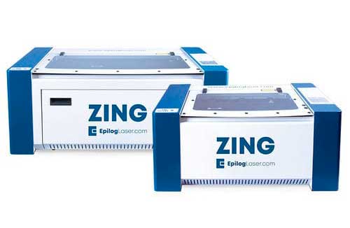
Epilog Laser Zing

This reference guide provides essential safety precautions and best practices for operating the Epilog Laser Zing at Fab Lab Cuenca. For more information on specific machine settings and material compatibility, refer to the Epilog Laser Zing User Manual:

⚠️ General Safety Precautions

  • Always close the laser cutter lid before starting a job.
  • Never leave the machine unattended while it is operating.
  • Do not use the machine if you detect an abnormal state (such as an unusual smell, excessive smoke, or unusual noises).
  • Ensure proper ventilation is active before starting any cutting or engraving process.
  • Never work with PVC or other hazardous materials, as they release toxic fumes that can damage the machine and be harmful to your health.
  • If an emergency occurs, immediately turn off the power and notify the Fab Lab manager.

🔧 Operating the Laser Cutter

Before Starting a Job

  • Check that the machine is in good condition.
  • Ensure the bed is clean and free of debris.
  • Verify that the laser lens is clean and undamaged.
  • Check that the air compressor and ventilation system are functioning.
  • Select the appropriate material (e.g., acrylic, wood, EVA foam).
  • Adjust the cutting and engraving parameters according to the material thickness.
  • Position the material properly and focus the laser.
  • Run a test cut to ensure the settings are correct.

During Operation

  • Stay close to the machine and monitor the process in case of unexpected issues.
  • Be cautious of flames or excessive smoke, as these could indicate improper settings or hazardous material reactions.
  • Use appropriate power and speed settings to prevent overburning or incomplete cuts.

After Completing a Job

  • Wait for the machine to cool down before turning it off.
  • Remove any leftover materials or debris to keep the working area clean.
  • Turn off the ventilation and air compressor once finished.

🚫 Prohibited Actions

  • Do not touch the laser lens.
  • Do not introduce metal, combustible, or volatile materials into the machine.
  • Do not unplug the power cable by pulling it directly.
  • Do not disable safety features or protective covers.

Emergency Procedures‼️

Fire Occurs

Immediately use the emergency stop button and notify the Fab Lab manager.

Machine Gets Stuck or Malfunctions

Turn off the machine and manually reset it before restarting.

Long Running Time

Allow the laser to cool before shutting it down to prevent overheating.

User computer interface

Below I show some screenshots of the interface for laser cutting:
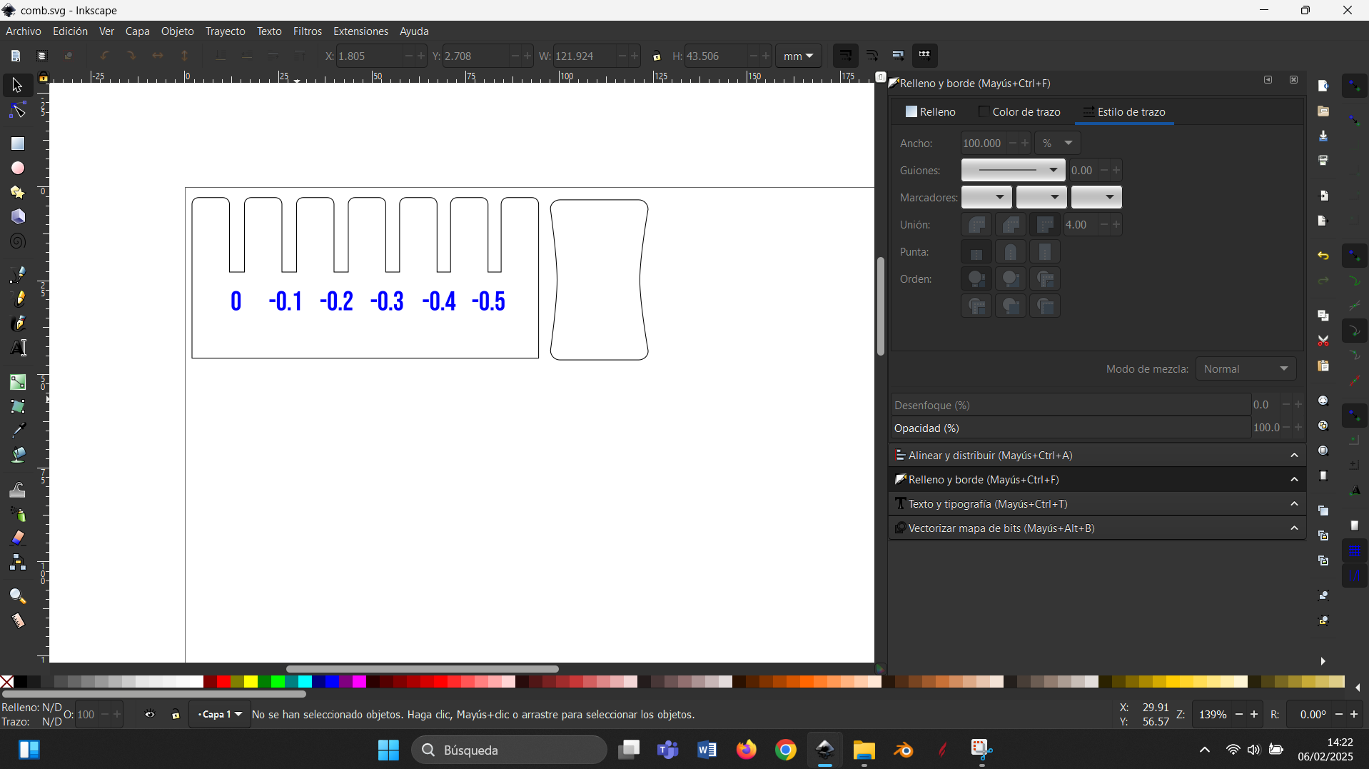
Inskape graph
Inskape graph

Here colors black and blue represent cutting and engraving respectively.


Print
Print


Printer selection
Printer selection


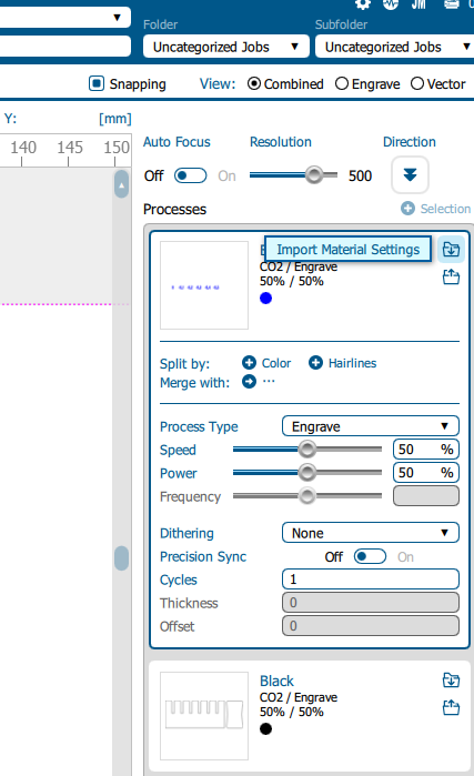
Epilogue Interface
Epilogue Interface


Cutting parameter selection


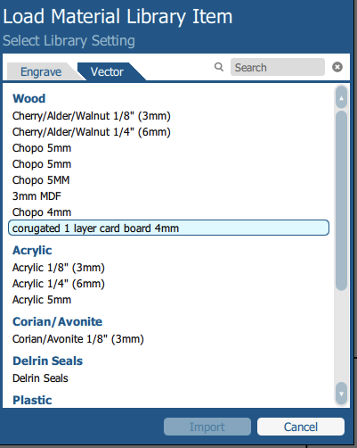
Material Library
Material Library

⚙️ Laser Cutter Calibration & Material Testing

Once safety training was completed, we conducted a series of tests to characterize the laser cutter’s performance and understand how different settings affect materials. Our focus was on:

  • Finding the optimal focus for clean cuts.
  • Testing power & speed settings for engraving vs. cutting.
  • Measuring the kerf (material loss) for precise fits.
Machine

Laser Cutting Tests

Material Test Card

Material Test Card

To determine the best laser cutting and engraving settings, we created a Material Test Card that allowed us to evaluate different power, speed, and engraving configurations. We tested:

  • Engraving Power Variations (5%, 10%, 20%) – This helped us compare shading effects and determine how different power levels affect the material's surface.
  • Speed Adjustments – By altering the laser speed, we observed how slower speeds created deeper engravings while faster speeds resulted in lighter surface markings.

The Material Test Card provided us with a quick reference for achieving clean and precise engravings while minimizing burn marks or excessive depth. This information was especially useful for optimizing settings in our individual assignments and parametric construction projects.

Measuring Laser Kerf

Measuring Laser Kerf (Comb Test)

Kerf is the width of material removed by the laser beam, and understanding it is critical for designing interlocking parts in parametric projects. To measure the kerf, we:

  • Designed a comb test file with slots of different widths.
  • Cut the design and measured the actual slot widths.

📏 Key Learnings from Laser Cutting

Through this process, we gained several important insights about working with laser cutters:

  • 🔥 Fire safety is critical, especially for flammable materials like cardboard.
  • ⚙️ Always test on scrap materials first before finalizing settings.
  • 📏 Measuring kerf is necessary for precision in interlocking designs.
  • 🔍 Lower power settings prevent excessive burns in engravings.
  • 💨 Ventilation must always be on to prevent fumes from accumulating.

These findings will directly inform our individual assignments, where we design parametric construction kits using laser cutting techniques.

📂 Download Files

You can download all our test files and design files using the link below:

Fabruary 12, 2025

Week 4
embedded programming

Laser Test Alfredo Measurement Camila

Group assignment: Demonstrate and compare the toolchains and development workflows for available embedded architectures This page documents our findings, testing results, and key learnings

Group Task Distribution

Task Person Responsible
Compare the toolchains and development workflows Both
Xiao Alfredo
micro:bit Camila
Raspberry Alfredo
Arduino Camila

Getting Started with Micro:bit

micro:bit

The first tool we tried was MakeCode, Microsoft's block-based coding interface. It is very intuitive—perfect for beginners—since it allows users to drag and drop blocks to create logic. One feature that stood out was the built-in simulator, which lets you test your code without flashing it to the actual board. This was great because it saved time when debugging basic logic errors.

First Program: Button Input & LED Output

We created a simple button press program:If Button A is pressed, the LED matrix displays a smiley face. If Button B is pressed, a sad face appears.

Once we got this working in MakeCode, we switched to JavaScript mode (which MakeCode supports). The transition was smooth since MakeCode provides a direct translation from blocks to JavaScript.

Then, we tried MicroPython, using the Micro:bit Python Editor. One cool thing we discovered in MicroPython is that you can modulate the LED brightness, something that isn’t possible to do in MakeCode.

micro:bit

Now that we had basic programs running, we decided to experiment with more sensors and outputs.We tested a buzzer, then the microphone sensor. One of the most fun experiments was using the Micro:bit radio module to send messages between two devices. We coded two Micro:bits to act as a transmitter and receiver, sending an icon in our LEDs (a duck) wirelessly. This is a feature that is very easy to use in MakeCode.

micro:bit

Comparison Insight:

MakeCode

Super easy to use, great for fast prototyping.

JavaScript

More flexible than blocks but still user-friendly.

Python

Provides lower-level control over hardware but requires more typing and coding skills..

Velostat Pressure Sensor

I wanted to try something more interactive, so I made a touch sensor using Velostat. Velostat is a material that changes its resistance when pressed, so I used it as an input for the LED matrix: If lightly pressed, just one LED glows, when pressed harder, all the LEDs glow.

Cami: This was an important experiment for my final project, where I plan to create interactive circuit-based activities.

Testing Arduino & C++

Arduino

We also tested Arduino, switching to a different coding environment. Instead of block-based programming, Arduino requires writing code in C++ using the Arduino IDE.

First Program: Blinky LED

The classic "Hello World" of embedded programming! This simple program blinks the onboard LED every second.

void setup() {
	pinMode(LED_BUILTIN, OUTPUT);
}
										  
void loop() {
	digitalWrite(LED_BUILTIN, HIGH);  // turn the LED on (HIGH is the voltage level)
	delay(1000);                      // wait for a second
	digitalWrite(LED_BUILTIN, LOW);   // turn the LED off by making the voltage LOW
	delay(1000);                      // wait for a second
 }

After making it work, we decided to experiment by adjusting the blinking frequency. By reducing the delay, we made the LED blink much faster, helping us understand how microcontrollers handle timing.

Raspberry pi pico

Main characteristics

Pico pin diagram

from:

pico 1 documentation

Some terms definitions (from Wikipedia)

For testing I used Arduino IDE and included a blink led code in C++ from the basic scripts Arduino provides.

Pico pin diagram

Xiao ESP32 S3

The Xiao ESP32 S3 sense is a powerful little (21 x 17.8mm) micro controller.

Characteristics

Some diagrams for the ESP32S3 sense follow.

Sense_front_indication

A more detailed schema of the board can be found below:

XIAO reference

In case you are looking for the user led for this model, thanks to Pablo from FL Leon I went to look harder for this. You can find it in diagram below.

user led location

Another well documented page for this controller developed by the DroneBot Workshop is provided below.

XIAO reference 2

I found this micro controller in AliExpress for 15.99 euros so it quite affordable.

Testing

As I had already used C++ through the Arduino ID for this week I wanted to use something different. For this purpose I installed the IDE Thonny and uploaded the firmware to the board, you can see the documentation for this in my individual assignment if you need it. The library esp32 has the function **mcu_temperature()** that allows you measure the board temperature. As you can see you can run interactively python command in the console of Thonny.

Check Controller Temp

And I also tested a blink the user led program.

i = 0;
from machine import Pin
from time import sleep 
led_pin = 21
led = Pin(led_pin, Pin.OUT)
for i in range(10):
  led.on()
  sleep(1)
  led.off()
  sleep(1)
  print("Blink",i+1)
Fabruary 19, 2025

Week 5
3D scanning and printing

Group assignment:
Test the design rules for your 3D printer(s)

For this week’s Group Assignment , we explored the design rules of multiple 3D printing technologies, with the Prusa mini, Bambu A1 Mini and resin printing (SLA). The goal was to understand how different printers and materials handle overhangs, wall thickness, bridging, infill, and support structures.

3D Extrusion Printers

Some important printer characteristics can be found below:

  • Nozzle diameter: will impact the layer thickness of the material being deposed. The tip of the noozle also pushes the material being extruded. The layer should not be larger than the nozzle diameter. Nozzle diameters vary from 0.25 to 0.8mm.
  • Working area: important to select the right area for the size of model you are building.
  • Table positioning: can impact the attachment of the piece to the surface. Auto leveling helps control this.
  • Chamber: a chamber is useful with materials that shrink when cooling which produce breakage if different parts of the model cool at different rates.
  • Temperature: different materials might need different temperatures for being struded.
  • Material extruder: whether is direct or bowden.

Slicer Characteristics

Some print characteristics that can be controlled through the slicer are:

  • Layer height, however is related to the nozdle size.
  • Infill percentage will determine the percentage of material inside the object being printed.
  • Number of horizontal and vertical walls.

Nozzle diameter will affect the definition/detail on the horizontal plane while layer height will affect the detail on the vertical and slanted sides . As a rule of thumb layer height should not exceed 80% of nozzle diameter (Prusa’s blog).

https://blog.prusa3d.com/everything-about-nozzles-with-a-different-diameter_8344/

Nozzle horizontal plane definition(source=Prusa’s blog)
Layer height and definition(source=Prusa’s blog)

In addition to layer height a slicer will let you specify vertical and horizontal walls as number of layers. For the vertical walls in the image below subtract the shown vertical outside walls rom the walls above the purple surface which should give 3. It is adviced to have more top layers compared to bottom ones as the top will have only the infill for support which could cause the filament to drip contrary to the bottom wich is supported by the printer’s platform. In general the amount of material will vary between a functional print and a aesthetic one.

Similarly, one can specify infill as a percentage are the red layers (rhomboid shape) inside the cube.

Below you can find a picture of useful utensils that come handy with an extrusion printer.


Safety Guidelines for Extrusion 3D printing [in our lab]

Materials needed for operation

  • Filament.
  • IIsopropyl alcohol (>90%).
  • Spatulas, forceps, cutting tools and tools to dislodge filament.
  • Cleaning wipes

Personal Protective Equipment

  • Depending on the material being printed you may need:
  • Respirator
  • Apron
  • Gloves

Operation sequence

  • Unload filament if a new one is to be used.
  • Load filament and
  • Purge the remaining filament
  • Slice stl file and according to your application adjust for:
    • Vertical and horizontal walls
    • Infil
    • Material,
    • Nozzles size,
    • Temperature
    • Supports
    • Etc..
  • Make sure it fits on the plate!
  • Check your sliced object to make sure there are not problems
  • Print G file and save it to a USB or send it throught wifi depending on the printer.
  • Keep an eye from time to time on the printer
  • Collect your print and clean the area.

Operation Precautions (People)

  • Be aware of the characteristics and safety guidelines of the materials you are using.
  • Use filaments that correspond to the printer settings and if possible use ones that have lower emissions.
  • Operate the printer in a well ventilated place.
  • Avoid standing close to the printer for long periods of time.
  • Be careful if you use alcohol to clean the printer’s plate as it is highly flammable.
  • Avoid touching heated platforms or hot nozzles.
  • Wash your hands after/before utilizing the printer
  • Disconnect the printer if changin/repairing printer pieces to avoid electric shock.

Operation Precautions (Machines)

  • Clean the machine’s plate with alcohol after each print in order to avoid grease build up.
  • Use appropriate filaments with their correct settings.
  • Avoid build up of dust as this increases.
  • If you change a nozzle make sure you update your slicer settings.
  • Let the model print cool down before removing it from the printer’s platforms.
  • Clean the work area thoroughly when finished.
  • Dispose residual filament appropriately.

Our Lab Safety Guidelines for Extrusion Printing

Prusa Mini

Below you can find a diagram of the Prusa Mini from:

https://help.prusa3d.com/article/glossary-mini_125081

From this article is important to note:

  • 8-Main PTFE tube (Bowden-tube): leads the filament strand from the extruder into the print head/nozzle. Inspect it from time to time to make sure there is no debris inside that would prevent the filament strand from reaching the nozzle.

  • 10-Print fan: cools the printed object, and improves print quality. Comes with RPM monitoring.

  • 11-Print head: Lightweight print head consisting of the hotend (printing nozzle), M.I.N.D.A. sensor, and two fans. The heaviest parts of the extruder were moved onto the Z-axis tower to improve print quality.

  • 14-Extruder / Extruder motor: as opposed to 3D printers like MK2 or MK3S, the extruder motor is not moving along the X-axis. Instead, it’s fixed on the side and pushes filament through the PTFE tube towards the print head.

which make the Prusa Mini is a bowden extruder. Bodwen extruders present the following pros and cons:

Pros: - Cleaner movements: as the extruder is not located in the printer head allowing faster movements and better print quality. - Larger build volume: as it allows for a smaller head carriage.

Cons: - Needs a more powerful motor. - Slower response times due to the distance between the print head and extruder. - Material complications flexible materials can bind or wear in bowden tubes.

from: https://all3dp.com/2/direct-vs-bowden-extruder-technology-shootout/

The slicer for the Prusa Mini was configured as:

with an infill of 15% and using the generic PLA setting for type of material.

Bambu A1 Mini (Q) - General Features

The Bambu A1 Mini (Q) is an advanced entry-level 3D printer that offers high-speed and high-precision printing with an easy-to-use interface. This model is designed to provide a seamless printing experience with minimal setup time.

The A1 Mini (Q) is an excellent choice for beginners and professionals alike, offering reliability and ease of use with features that make 3D printing more efficient and precise.

Bambu A1 Mini 3D Printer

Key Features:

  • Build Volume: 180 × 180 × 180 mm
  • Nozzle Diameter: 0.4 mm (default), supports 0.2 mm and 0.6 mm
  • Layer Height: 0.1 - 0.3 mm
  • Extruder Type: Direct Drive for improved performance with flexible filaments
  • Printing Speed: Up to 500 mm/s
  • Acceleration: 10,000 mm/s² for ultra-fast movements
  • Temperature: Max extruder temperature 300°C, heated bed up to 100°C
  • Auto Bed Leveling: Uses LIDAR-assisted calibration for precise first-layer adhesion
  • Multi-Color Printing: Compatible with the AMS (Automatic Material System) for seamless filament changes
  • Filament Compatibility: PLA, PETG, TPU, ABS, ASA, and more
  • Connectivity: Wi-Fi, SD card, and USB support
  • Software: Works with Bambu Studio and third-party slicers

Resin 3D Printers (SLA)

Important Resin Printer Parameters

The documents that follow describe some key parameters of resin printers:

https://store.anycubic.com/blogs/3d-printing-guides/3d-printing-parameters-of-resin-printer?srsltid=AfmBOooAoccop8OxJFcS33-srpdOZS5MyuufMflMYK0Aj16zgqottKCG

and

https://store.anycubic.com/blogs/3d-printing-guides/common-parameters-description-of-resin-printer?srsltid=AfmBOor3nFigVD1I4lttoq839dnrujBsUfNk5XFMOtClglgzMIOD_bjd

I have summarize these in ChatGPT with the following prompts: Summarise in 3 to 4 lines:…

Exposure time: controls how long resin is cured with UV light, affecting print quality and accuracy. Too short or too long exposure can cause weak, brittle, or swollen prints. Factors like resin type, temperature, and layer thickness influence the ideal exposure time.

Bottom Exposure time: The bottom layer is the first printed layer, and its exposure time affects adhesion to the platform. A longer bottom exposure time improves adhesion, preventing warping or detachment. Both bottom exposure time and the number of bottom layers determine print stability. Model size, weight, bottom contact area and resin properties.

The optimal operating temperature for the resin is around 24°C, which may vary slightly depending on the resin type.

Number of Bottom layers: Bottom layers are the initial layers exposed for a longer time to ensure strong adhesion to the platform. More bottom layers increase adhesion but can make the base larger than other layers. Around six layers are recommended, but the ideal count depends on model size, weight, and resin type. Taller models generally require more bottom layers for stability.

Off time: is the interval between the platform stopping and the next exposure, typically 1-3 seconds. It allows resin to flow back and stabilize, ensuring even layer formation. Higher viscosity, low temperatures, or large print areas require longer off times.

Z Lift Distance: Z lift distance is the vertical movement of the build platform between layers, ensuring proper layer separation. A precise distance prevents print or platform damage while optimizing print time. Reducing lift distance speeds up printing but may cause separation issues due to FEP film elasticity. It is generally recommended to use the default settings.

Z lift Speed: Z lift speed is the rate at which the build platform rises between layers, affecting print stability. If too fast, it creates high tensile force, risking cracks or failures; if too slow, it increases print time.

Anti-aliasing: smooths jagged edges in resin prints, improving surface finish and reducing layer stepping. Higher settings enhance edge quality but increase slice time and file size. It works alongside gray level and image blur techniques to refine pixel patterns in each layer.

Safety Guidelines for Resine Printing [in our lab]

Materials needed for operation:

Personal Protective Equipment(PPE)

  • Googles
  • Gloves
  • Respirator
  • Apron

Operation sequence

  • Raise built area and allow for resin to drain.
  • Remove cover from the printer
  • Unlock the build area platform and remove it with care.
  • Pry the print object apart from the build area with the spatulas [Check with MPI]
  • Replace build platform and cover to the printer
  • Perform an initial wash to remove the excess of resin and clean the tools used to pry open the print model.
  • Open the Anycubic wash container and place the print.
  • Close the lid of the wash container and set the washing clock, press knob to start.
  • Once time is over unlock the washer, take out the print and dry it. Replace the cover of the washer so the isopropyl won’t evaporate.
  • Once dry, place in the curing machine and place the UV protection cover.
  • Set the timer and wait until the print model is cured.

Operation Precautions (People)

  • Be aware that many resins are toxic.
  • UV exposure can be harmful to skin and eyes.
  • Be also aware that isopropyl alcohol is highly flammable and take appropriate precautions.
  • Prior to operating the machine read the safety data sheet for the resin to be used and be aware of what are the procedures if you were exposed to them.
  • Warn someone that you will be working with this resin 3D printer.
  • Make sure that the area of work is well ventilated.
  • Wear personal protective equipment described above at all times.
  • Operate machines with lids closed.
  • Make sure you close the lids of all containers you open after their use.
  • Ask the lab manager if you have any doubts.

Operation Precautions (Machines):

  • Clean equipment and machines if they are contaminated with resin.
  • Replace the printer resin container if you find a leak.
  • Remove resin from the printer container if you will not print anything else in the next 48 hours.
  • Dispose of residues appropriately, do not flush them down the sink.
  • Clean the work area thoroughly when finished.
  • Inspect and clean your protective gear thoroughly after each use.

Our Lab Safety Guidelines for Resine Printing (Photon Mono X)

Photon Mono X

The Photo Mono X is a fairly big size resin printer from Anycubic


Some of the printer characteristics:

  • Build Volume: 192mm(L)x 120mm(W)x 245mm(H)
  • Light-source: high-quality filament(wavelength 405nm)
  • XY Res.: 0.050mm 3840*2400(4K)
  • Z Axis Res.: 0.01mm
  • Layer Res.: 0.01-0.15mm
  • Printing Speed: MAX 60mm/h

Resin Printer Configuration

For the resin printer we had two settings as for the first print (in grey) we observed an elephant foot. For the second the exposure time for the bottom layer was reduced from 28 to 18. We also changed the resin (white.)


Test design Rules

1. Negative Tolerance Test

We found that 0.05 and 0.10 millimeter would lock in the two pieces. The former is too tight and might not be the most appropiate size difference between the two pieces.

2. Thickness Test

Overall, for the thickness test we found the thickness decrease from left to right for the Prusa printer(white). However, it would seem that given the diameter of the nozzle is 0.4, some of the smaller width repeated. This was not the case for the resin printer(grey) which printed one additional thickness, and were you can see that all the thickness decrease from left to right.

3. Bridging Tests

The bridging test was successful for the Prusa printer. For most bridges length there were some lines of filament that hanged from the bridges bottoms. The maximum bridge length attained was 8 cm.

4. Angle Test

The angle test was a bit redundant as we had already seen that “parallel to the ground” bridge construction was possible. However it was interesting to see that there were some residual filaments only on 0 and 10 degrees from the ground plane.

5. Overall test resin

We could observe that in resin we were capable of building very fine structures….

Bambu A1 Mini - Testing Results

Below are the results of various print tests conducted using the Bambu A1 Mini.

3D Print Testing Results

1. Wall Thickness Test

  • Print Time: 23 min 38 s
  • Observations: The print quality was excellent. Thin walls were well-defined, but the first three layers (0.1, 0.2, 0.3 mm) did not print due to slicer limitations. Most slicers establish a minimum threshold based on the nozzle diameter. If a feature is thinner than this threshold, it may be automatically omitted to prevent printing errors. Adjusting the extrusion width settings in Bambu Studio could help resolve this.
3D Print Testing Results

2. Bridging Test

  • Print Time: 28 min 38 sec
  • Observations: Bridges up to 5 mm were good, but at 9 mm and 10 mm, there was noticeable stringing and sagging.
3D Print Testing Results

3. Angle Test

  • Print Time: 49 min
  • Observations: Overhangs remained stable up to 30°. At 10° and 0°, noticeable imperfections appeared.
3D Print Testing Results

4. Tolerance Test

  • Print Time: 54 min
  • Observations: 0.1 mm tolerance fits well with a firm grip, similar to laser-cut fits.
3D Print Testing Results

Tested Infill Patterns

  • Honeycomb: Excellent strength-to-weight ratio, ideal for structural parts but increases print time.
  • Cross Hatch: Balanced strength and speed, useful for general-purpose prints.
  • Adaptive Cubic: Optimized for strength while using minimal material, dynamically adjusts density.
  • Cubic: Strong and efficient for load-bearing parts, faster than honeycomb.
  • Octagram Spiral: Visually unique, flexible but weaker than the other patterns, suitable for aesthetic prints.
Fabruary 26, 2025

Week 6
Electronics Design

use the test equipment in your lab to observe the operation of a microcontroller circuit board.

Understanding Electronic Testing & Measurement

Before diving into hands-on testing, it’s important to understand the essential concepts behind electronic diagnostics. Electronic circuits are built upon voltage, current, and resistance, and each component behaves differently under these conditions. Testing tools allow us to measure, visualize, and troubleshoot these properties effectively.

Group Task Distribution

Task Person Responsible
Multimeter Camila
Power Supply Alfredo
Logic Analizer Camila
Oscilloscope Alfredo

Exploring Test Equipment for Electronics Design

Power Suppy

The Hanmatek 305 is a power suppy with knobs to control the voltage and the amperage in a range of 0-30 Volts and 0-5 Amperes respectively. In addition, there is a safety button to stage the changes made in these knobs. We used the device to to run different sizes motor to guess what were the operating ranges by varying the voltage and amperage.

Oscilloscope

While the multimeter takes an average of the signal at point in time giving a single value, the oscilloscope is used to measure an electrical signal dynamically throughout time.

In this video you can see the electricall signals as we change from DC to AC.


For this purpose we ran a micro python program where we turn on and off a pin in the Xiao ESP32S3 micro controller.

from machine import Pin
from time import sleep
on_pin = 4
pin = Pin(lon_pin, Pin.OUT)
for i in range(1200):
  pin.on()
  sleep(1)
  pin.off()
  sleep(1)
  print("on",i+1)

In the video above the bottom labels indicate:

  • the vertical separation on the vertical axis (in this case 2 volts)
  • the attenuation of the probe,
  • the horizontal separation of the measurements in the horizontal axis (in this case 5\(\mu\)S)
  • and the type of current being measured (AC/DC)

Multimeter: The Go-To Debugging Tool

A multimeter (Measures electrical properties such as voltage, current, and resistance) is the first tool you reach for when something in a circuit isn’t working. We used it to:

  • Check LED polarity (because putting them in backward is a classic mistake).
  • Test continuity in cables—some of the wires in the Fab Lab were unreliable, so we had to confirm which ones were actually conducting.
  • Measure voltage levels to ensure our power lines were supplying the right amount to the microcontroller and components.

Logic Analyzer: Seeing Data in Action

While a multimeter is great for checking voltages, when it comes to digital signals and communication protocols, we needed something more advanced—a logic analyzer(Captures and visualizes digital signals to analyze communication protocols.). We worked with a Saleae Logic Analyzer, which is essentially a device that "listens" to data traveling between components and helps us visualize what’s happening, We saw a video to guide us: Decoding UART, I2C and a non-standard signal

  • We clipped it onto an Arduino’s TX and RX pins to monitor serial communication.
  • The "Logic" software let us capture and analyze the data being sent and received.

We could see real-time data packets moving across the screen, confirming that our Arduino was actually transmitting information correctly.

void setup () {
	Serial.begin(9600);
	delay(1000);
}
																	
void loop() {
	Serial.println("hello camila and alfredo!!!");
	delay(2000);
}
								

Why These Tools Matter in PCB Design

This assignment wasn’t just about using test equipment—it was about developing a debugging mindset. It’s easy to assume a circuit will work just because the schematic is correct, but real-world electronics always have surprises.

Key takeaways:

  • A multimeter is your best friend for checking power, connections, and basic functionality.
  • A logic analyzer is a game-changer when working with communication protocols—it helps you actually see what's happening in your circuit.
  • Always test your components before soldering them—bad wires or incorrect polarity can cause hours of frustration later.

Marcg 05, 2025

Week 7
Computer-controlled machining

This week at Fab Academy, we focused on CNC machine safety, setup, and calibration to ensure proper operation before cutting. The session covered lab safety training, machine controls, tool selection, and materials.

🔧 Lab Safety Training

Before operating the CNC machine, it was crucial to complete a safety training session. The CNC milling machine is a powerful tool, and improper use can lead to injuries, tool breakage, or material damage.

Key Safety Considerations

Personal Protective Equipment (PPE)

  • Safety glasses: Protect against flying debris.
  • Hearing protection: CNC machines can be loud.
  • No loose clothing, jewelry, or gloves: These can get caught in moving parts.
  • Closed-toe shoes: Protect feet from falling tools or materials.
Bambu A1 Mini 3D Printer

⚠️ Emergency Stop and Safety Protocols

  • The Emergency Stop (E-Stop) button immediately halts all operations.
  • Power failures or sudden machine malfunctions require a manual reset before resuming operations.
  • Fire hazards exist when cutting flammable materials, so a fire extinguisher must always be within reach
  • A first aid kit should be easily accessible in case of minor injuries.
Bambu A1 Mini 3D Printer

CNC Machine Overview & Controls

For this assignment, we used the Fresadora CNC 1325, a mid-size CNC router equipped with an air-cooled 4.5 kW spindle, a vacuum bed.
Machine Components The main components of the CNC router include:

  • Spindle: The motorized cutting tool, capable of reaching 18,000 RPM.
  • Worktable: The machine features a vacuum table that helps secure materials during cutting.
  • Linear Motion System: The X and Y axes move using a rack-and-pinion system, while the Z-axis is controlled via a ball screw drive.
  • Control System: The DSP handheld controller allows the operator to move the spindle and set the zero position manually.
Bambu A1 Mini 3D Printer

Setting the Home Position we must set the home position (machine zero):

  • Move the spindle to the desired origin point (X, Y, Z).
  • Use the DSP controller’s movement keys to fine-tune the positioning
  • Set this point as the zero reference by pressing "XYZ Zero".
  • Control System: The DSP handheld controller allows the operator to move the spindle and set the zero position manually.
Bambu A1 Mini 3D Printer

Router bit

The choice of router bit determines the cutting efficiency and final surface quality. We tested several types of bits: Common Router Bits & Their Applications

Source: ToolsToday Learning Desk


Ensuring CNC Precisiong

Runout: Checking Tool & Spindle Accuracy

Before diving into machining, we performed a runout test directly on the CNC router to check if the spindle and tool were properly aligned. Runout happens when the cutting tool doesn’t rotate perfectly centered, causing wobbling. This can lead to inconsistent cuts, uneven slot widths, rough edges, and faster tool wear.
We ran a test by cutting parallel slots into the material at different feed rates and speeds to observe any variations in cut accuracy and edge finish. The image below shows the results, where we measured slot widths and noted speed settings. Our findings confirmed that runout on this CNC machine was minimal, meaning the spindle and collet were well-calibrated.


Dial Indicator Test

Why Did We Also Use a Dial Indicator?

Even though the CNC’s runout was minimal, we wanted to better understand how misalignment impacts precision, so we performed a secondary test using a dial indicator on a smaller milling machine. This allowed us to visualize how small tool or spindle misalignments affect precision.
By rotating the spindle manually and observing the needle movement on the dial, we saw how even slight shifts in alignment could impact cut quality. This reinforced the importance of checking tool seating and spindle calibration before machining.


Speeds and Feeds

Understanding Feeds, Speeds, and Chip Load

One of the most crucial aspects of CNC machining is setting the correct feed rate, spindle speed, and chip load to achieve clean, efficient cuts while preventing tool damage. These parameters determine how fast the tool moves through the material, how deep each pass should be, and how much material is removed per revolution. We used the spreadsheet calculator from “Calculating Feeds and Speeds – A Practical Guide | Wood CNC Router” by Cutting It Close to determine the optimal settings for our tool and material.

Chip Load Calculation Formula

The chip load is the thickness of the material removed by each cutting edge of the tool. Proper chip load values help ensure that the tool doesn’t overheat or wear out too quickly. We calculated our feed rate using the following formulas:

Feed Rate Formula:

Tool Diameter Hardwood (Chip Load) Softwood/Plywood MDF/Particle Wood Soft Plastic Hard Plastic
3mm 0.08 - 0.13 0.10 - 0.15 0.10 - 0.18 0.08 - 0.15 0.05 - 0.10
6mm 0.23 - 0.28 0.28 - 0.33 0.33 - 0.41 0.18 - 0.26 0.15 - 0.23
10mm 0.41 - 0.46 0.43 - 0.51 0.51 - 0.59 0.26 - 0.31 0.20 - 0.26
13mm & up 0.48 - 0.54 0.54 - 0.59 0.64 - 0.69 0.31 - 0.41 0.26 - 0.31

Using these formulas, we adjusted our settings to maintain a balance—avoiding a feed rate that’s too slow (which could cause burning) or too fast (which could break the tool or create rough edges).

Feed Rate Table

Below is the feed rate table we used to determine the correct cutting parameters based on tool size and material.

Feed Rate Table for CNC machining

If you’d like to reference or modify the calculations, you can download the feed rate spreadsheet here:

Vacuum Table & Sacrificial Board

Why Material Holding Matters? Before any CNC machining operation, one of the most critical steps is securing the material. If the workpiece moves, even slightly, during the cutting process, it can cause misalignment, rough edges, tool breakage, or even machine damage. To ensure stability, two common methods are used: vacuum hold-down systems and sacrificial boards.

Bambu A1 Mini 3D Printer

How the Vacuum Table Works

A vacuum table uses negative pressure to hold down the material during machining. The principle behind it is simple: atmospheric pressure pushes down on the material while the vacuum pump removes air from beneath it, creating a pressure difference that keeps the workpiece firmly in place.

How Strong is the Hold?
The force holding the material depends on the vacuum pressure and the surface area of the material. A larger material has more surface area in contact with the vacuum, increasing the holding force.

See the diagram below for a visual explanation of how vacuum tables generate hold-down force
See the diagram below for an illustration of cutting forces acting on the material

Source: Mekanika.io

The CNC router we worked with has a vacuum table divided into six independent sections, controlled by valves. Each section can be activated or deactivated depending on the size and position of the material being cut. By closing certain valves and keeping only the necessary sections open, we could optimize the suction force applied to the board, making sure it stayed completely flat against the sacrificial board.

Bambu A1 Mini 3D Printer
Factors Affecting Vacuum Strength:

Sacrificial Board

The Role of the Sacrificial Board A sacrificial board is a layer of material placed between the CNC machine’s bed and the workpiece. Its main purpose is to protect the CNC table from tool damage while also improving vacuum performance.

Bambu A1 Mini 3D Printer
Source: Cutting It Close "Calculating Feeds and Speeds A Practical Guide | Wood CNC Router"

---

File Preparation

Here I describe how to prepare the Aspire file for the CNC machine.

  1. We set up .SVG file or .DXF with the vectors to be cutted.

  2. Then in Aspire we set the dimensions of the board and the origin point.

  3. We go to file and import a vector file with the tracing of the object(see above).

  4. We can observe the imported trajectories where the CNC machine will cut.

  5. We set the cut depth and the number of passes.

  6. Then we set the tool characteristics.

  7. Subsequently we set taps/bridges.

  8. We can edit the taps displayed produced by the program.

  9. And finally, the software allows to do a simulation of the cutting.


Pre-programation of spindle and feed speeds

Below you can find a image of the of the CNC control where you can see the different keys needed to operate the machine:

The control will allow us to set up preconfigured spindle and feeds speeds. Below you can find the sequence of commands to program these parameters as to have a set of options

  • Press Menu → Auto Pro Setup → OK.
  • Scroll to G-code setup→ OK
  • Navigate to Read →press Run→ select ReadS→ press OK
  • Press Menu→ Enter Machine Setup → OK
  • Select Spindle Setup → OK
  • Select Spindle State→ OK
  • OK x2 to get to the speed set up menu
  • Set the spindle speeds as needed:
  • Level 8: 18,000 RPM
  • Level 7: 17,000 RPM
  • Level 6: 16,000 RPM
  • Level 5: 15,000 RPM (for acrylic work)
  • Level 4: 14,000 RPM

NOTE: Ensure that Aspire uses only these preset values (e.g., 18,000, 17,000, 16,000, etc.). Intermediate values like 16,500 will not be recognised by the controller.

  • Configuring Feed Rate Recognition
  • On the Rich Auto controller:
  • Go to Menu → Auto Pro Setup
  • Scroll down to Gcode setup → OK
  • Choose F Read→ press Run
  • Select Read F → press OK
  • And stop/cancel to go back to main menu
  • After completing these steps, the Rich Auto controller should correctly interpret both the
  • spindle speed and feed rate as defined in Aspire.

Actions prior to cutting

Decide on the the type of cutting needed and change the bit for one that is appropriate. For this, the case that holds the collet will need to be loosened with a couple of wrenches. Depending on the width of the shaft of the bit a different collet could be needed.

First snap the collet into the collet nut and then insert the bit. The shaft of the bit should not stick beyond the collet it should stay 3mm away from the end of the collet in case the bit is long otherwise it will not clamp well. Also, make sure that the flutes are not inside the collet.

source: cutting it close

Thereafter inspect the board to check that the board is even and flat. Otherwise correct for this with clamps or screws.

It is important to make sure that when setting the cutting area to take into account for this, in order to avoid that the milling over this metal pieces as it is very dangerous!

It is a good idea to test the table vacuum in order to see if the wood will move by pulling sideways.

Use the controller xy + and - buttons to re position the CNC head to the start point or origin. Remember that x increases from left to right, z from bottom to top and y increases from the control station to the back of the room. In order to set up the z origin it is necessary to take small steps to touch the board lightly with the bit. In order to do this it is a good idea to activate the table vacuum as this will change the z position of the board.

Cutting

  • Connect the usb drive to the controller.
  • Set up origin point: Then press XY->0 and Z->0.
  • Thereafter, select the Run/Pause key to call the file menu and select UDisk using the x+ and x- keys + OK.

  • After, you can select the Aspire file you created using the X+ and X- keys + OK

Note: The controller will use the parameters specified in the G-code as long as their values have been preset in the controller previously.

  • Prior to sending the job if you haven’t already turn on the table vacuum sections that you need and the extractor.


  • You may want to do a test run i.e. without cutting i.e. to see the trace. Make sure the you lift the CNC head in Z position to avoid cutting.

  • Send the job and stand in next to the control center always with a finger positioned in the stop key.

Tests

Press Fit Test

We created some cuts files for different path widths in order to evaluate fit of two pieces. Given that the regular dimensions of the board were 10mm we set up a range of slit widths from 10-10.8 with a step separation of 0.2 mm. We found that the 10mm cut provided a good fit but still could use some width reduction for better grip. We realized that the finger piece was actually 9.8mm in width. Then we cut an additional slit piece with 9.8 mm and this provided a good fit with good grip but was not excessively tight allowing still to separate them. Possible a 9.7mm slit would be great if we lookfor a permanent lock.


.

.

Dog Bones Test

We wanted to see if different dogbones shapes had an impact on the fit so we tested 3 different dogbone shapes with slit widths of 9.8mm. We were not able to identify any differences in fit. We used the Nifty Dogbone extension for Fusion 360 that can be found:

https://apps.autodesk.com/FUSION/en/Detail/Index?id=3534533763590670806&appLang=en&os=Win64

.

.

Files

March 12, 2025

Week 8
Electronic Production

Group Task Distribution

Task Person Responsible
Infromation and details of the machines we used Alfredo
Preparation of the files Camila
Design rules and results Camila
Sending a PCB to a boardhouse Alfredo

LUNYEE All-Metal 500W CNC Router Machine

Specifications:

  • Working area: 300x180x80mm
  • Machine size: 485x415x374mm
  • Spindle: stnd configuration: 500W 10000 r/min
  • Machine accuracy: +/- 0.1mm
  • Max speed 5000mm/min
  • Max cutting speed 2000mm/min
  • Power supply 48V 500W

This machine is suitable for milling: wood,bamboo,acrylic,plastic, PVC, ABS, PCB, brass and resin.

I general terms, the machine is composed of three axles to displace the milling bit into three directions. In the machine we have two pole terminals (+ and -) that are useful in determining the probe depth. One of the ends is attached to the head of the milling machine and the other other the board. Once the tip of the bit touches the metal plate it will complete a circuit, record the actual depth of the board surface.

Below we can find some safety guidelines:

  • Be aware where the stop button is.
  • Use appropriate goggles when operating the machine.
  • Use appropriate breathing protection given the material you are cutting.
  • If you have long hair tied it back.
  • Do not use gloves as they can get caught in the spindle.
  • Ensure proper ventilation
  • When changing bits disconnect the machine.
  • Make sure clamps are well fastened.
  • Make sure there is no wiring in the cutting area for example remove the probes terminal before cutting.
  • Double check that you have the right cutting area.
  • Stay close by the machine while there is a ongoing cut job.


For engraving in the second process we explored we used the following laser engraver.


ComMarker B4 MOPA 60

Specifications:

  • Laser Source: MOPA-JPT
  • Laser Power: 60W
  • Laser Wavelength: 1064nm
  • Engraving Accuracy: 0.01mm
  • Engraving Speed: 0-15,000 mm/s
  • Frequency 1-4000 KHz
  • Pulse Width: 2-500ns
  • Work Area: 110mm x 200mm dual lenses
  • Primarily designed for engraving metals and plastics
  • Can cut Stainless Steel, Aluminum, Brass, Copper, Silver and Gold.

In this page you can find a blog that describes the advantages that a fiber laser engraver have for PCB engraving. Below you cand find a short summary of this article.

The high precision laser technology of a fiber laser engraver allows to etch, cut and mark the different layers of a printed circuit board. Some specific advantages are:

  • High Precision and Accuracy to achieve fine detail.
  • Efficiency and Speed resulting in faster processing than traditional methods thanks to high speed galvo technology.
  • Versatility: that allows processing several types materials.
  • Auto Focus Technology: Allows adjustments based on material thickness and variations in the material surface.

This is a laser cutter that uses the MOPA technology i.e Master Oscillator Power Amplifier. This technology has a much wider frequency range than q-switch machines and it can also control the pulse width parameter enabling the control of the individual laser pulses.

In the fields of Electronics, Semiconductors, and ITO Precision Machining achieving precise lining is often essential. However, a Q-switched fiber laser struggles with this task due to its fixed pulse width. In contrast, a MOPA fiber laser, with its adjustable pulse width and frequency, effectively delivers smooth edges and precise results. Mopa Fiber laser has a tunable wdith which facilitates small laser spot and tunable energy (source: link)

Steps for engraving a PCB:

    1. Design Circuit Diagram
    1. Input the Circuit Diagram into EZCAD in our case we have a version of Lightburn.
    1. Set Parameters power, speed, and frequency
    1. Preview and adjust position and size
    1. Initiate the laser engraving process.
    1. Check the result.

Safety

These are some complementary safety guidelines to the ones that were described in week 3 as this is very powerful and potentially dangerous machine from the manual:

This is a powerful and potentially dangerous machine. We use an emergency stop button, which is important to quickly shut down the system in case of any issue.
The machine is also operated inside a protective case, which helps contain laser reflections and ensures safer use.
You can see the setup in the image below, where both the safety enclosure and the emergency stop button are highlighted.
Here is the enclosure we currently use for the fiber laser:
ComMarker Fiber Laser Safety Enclosure

Bambu A1 Mini 3D Printer
  • Laser Safety
    • The machines use Class Ⅳ lasers. The lasers are very powerful and can cause eye injuries and burnt kin. It is recommended to wear laser goggles when using the laser engraver.
    • Avoid exposing your skin to Class IV laser beams, especially at close range.
    • Do not touch the laser engraving beam while it is switched on.
  • Material Safety
    • Do not engrave materials with unknown properties.
  • User Safety
    • Use this laser engraving device only in accordance with all applicable local and national laws and regulations.
    • Use this device only in accordance with this instruction manual and engraving software manual.
    • DO NOT leave this device unattended during operation.
    • Cut off all power to the machine and contact either our customer service or repair service if anything seems to be working abnormally
    • Any untrained personnel who might be near the device must be informed the danger of the machine before operation

Some of this are scary that they need to put them.


PCB Milling and Laser Engraving: Workflow and Results

For our PCB fabrication process, we used a CNC milling machine to remove copper and create circuit traces. This involved several key steps, from preparing the files to sending them to the milling machine. Additionally, we explored laser engraving as an alternative method. Below is a breakdown of our process.

Preparing the File
To generate the milling paths, we used mods project, an online tool that allows customization for different bit sizes and milling parameters. For this we use the test file that they shared in the global class.


When setting up the exterior cut in Mods, we explored the use of tabs, small uncut sections that keep the PCB attached to the base material during milling. This prevents the board from shifting or coming loose, ensuring a clean and precise cut while making it easier to remove afterward.

Sending the File to the CNC: Candle Software

With the G-code file ready, the next step was to send it to the milling machine using Candle, a G-code sender software, to control the CNC. The first step was to connect the machine and set the origin point for the milling process. This involved manually adjusting the bit’s height and using the jog controls in Candle to position the tool at the correct starting location.


Before starting the milling process, we performed a Height Map calibration. This step is crucial because even slight surface irregularities on the PCB material can affect the milling depth. The Height Map compensates for these variations, ensuring the milling bit follows the correct depth across the entire surface.
To create the Height Map, we first opened a valid G-code file—this step is required, as the software needs the defined area to place the probe points.
Then, in "Edit Mode", we used the Height Map tool to set up a "Probe Grid", which defines where the surface will be measured. More points mean better accuracy. Once the probing was done, we saved and applied the map before running the job.


After verifying all settings, we loaded the G-code file and initiated the milling process. The machine started by cutting the traces with the selected bit size, followed by the outline cut using the configured tabs to keep the board in place. Throughout the process, we monitored the cut.

Finally, once the milling was completed, we carefully removed the PCB, checked the trace quality, and cleaned the board to remove excess material. The result was a precise, well-milled PCB, ready for further processing.

In the image, we tested three different milling bit sizes:
The 0.1mm bit, located at the bottom , provided the sharpest detail, making it ideal for intricate traces and high-density PCB designs. However, due to its thin structure, it is also the most fragile and prone to breakage if not handled carefully. The 0.2mm bit, in the middle, offered a good balance between precision and durability, making it suitable for general PCB engraving while still maintaining fine details. The 0.4mm bit, at the top, was the most robust but resulted in wider traces, which may not be ideal for compact circuits but is useful for faster milling and larger traces. This test helped us determine the appropriate bit size based on the required level of detail and durability considerations for milling PCBs effectively.

Exploring: PCB Laser Engraving

For this test, we used a ComMarker B4 60W MOPA Fiber Laser to engrave a PCB instead of milling. We opted for engraving only since laser cutting the board leaves undesirable burns and discoloration. The goal was to test how different power settings and number of passes affected the engraving quality and depth.

Top sample (2 passes, 90% power): Produced a dark, well-defined engraving, with strong contrast against the copper surface. However, the material removal was limited, leaving a slight texture.
Middle sample (4 passes, 90% power): Increased the engraving depth while keeping clear and legible details. The copper was effectively removed, revealing a more uniform and matte finish.
Bottom sample (6 passes, 30% power): Despite more passes, the lower power setting removed less copper, resulting in a subtle and less contrasting engraving. The details are still visible but not as deep or pronounced as the 90% power tests.


For the laser parameters we chose: Speed of 1500 mm/sec, a Maximum Power 90%, a Pulse width of 250ns, and a frequency of 30Khz

Generating files in Kicad

One goal for this week was to simulate sending the PCB to a manufacturer for this we had to produce gerber files. Gerber files are a collection of files that are useful in the production of PCB’s. In order to generate the Gerber files we go to the file menu and then choose plots. Thereafter, choose the production settings from our chosen manufacturer.

The following video provides a quick description of the steps needed to take to produce a Gerber file that is formatted for the NextPCB board producer.

Generating Gerber Files in KiCad

At this time I could not find which options to choose in Kicad 9 as the interface has changed so there are two ways to go about this, one is to use the defaults the second one is to use a plugin. We start with the former.

File=>Fabrication Outputs => Gerber

The we get the following menu that you may want to modify if you know the correct settings.


As per the video above we use the defaults and select use protel file name extension. In addition, create a directory were you will output your files as it quickly can become a mess. Then press plot and you can see the files in the specified directory.

And then press generate drill files. This is useful if you have to drill some holes in your PCB e.g. for mounting it.

Thereafter, you will need to generate the zip file with all the files created in order to upload them to NextPCB page that you can see below.


And then you upload the zip file


Here you can see the different options chosen and the price of the boards and shipping resulting from the uploaded files.

The other way to do this is to install a plugging for the manufacturing company using the plugin and content manager in Kicad.


Once installed, you can calle it from the menu to verify the options given by the company’s plugin. Therafter, click update price to get a qoutation. You can also press add to cart and this will take you to the compay’s site as before to order the board.


Key Learnings


This week’s exploration of PCB manufacturing techniques gave a better understanding of the trade-offs between milling and laser engraving. The milling tests showed how bit size affects precision, and the importance of settings like depth, feed rate, and toolpath optimization. Using Mods for file preparation allowed us to refine the process for different bit sizes, ensuring better control over the cut. The height map calibration in Candle also proved essential for maintaining accuracy, especially when switching between tools.

March 19, 2025

Week 9
Input Devices

Group Task Distribution

Task Person Responsible
Analog Camila
Digital Alfredo

For this week’s Input Devices assignment, we explored both analog and digital input signals through simulation and real-world testing. We began by simulating a potentiometer in Tinkercad.

Analog Input - Accelerometer / Potentiometer

To explore input devices, we worked with both analog and digital sensors using simulation tools and real hardware. I started with an analog input test using Tinkercad, where I connected a potentiometer to an Arduino UNO. In the simulation, the potentiometer was wired with one side to 5V, the other to GND, and the center pin connected to analog input A0. I used a simple Arduino sketch to read and display the analog values via the Serial Monitor, which helped visualize the range of values as I turned the knob. The code used for this simulation is shown below:

int sensorValue = 0;

void setup()
{
  pinMode(A0, INPUT);
  Serial.begin(9600);
}

void loop()
{
  sensorValue = analogRead(A0);
  Serial.println(sensorValue);
  delay(10);
}

This program prints the analog signal from the potentiometer every 10 milliseconds, allowing me to see a smooth transition of values on the Serial Plotter. It helped me understand how analog signals behave and how sensors can reflect continuous variation based on physical input. You can view and interact with the simulation here by opening the shared project.
Later, I recreated this analog test physically by connecting a real potentiometer to an Arduino UNO, then used a multimeter and an oscilloscope to observe the voltage changes on the analog output pin.


For the multimeter test, I didn’t need to connect the Arduino to read values. Instead, I connected one outer leg of the potentiometer to GND, the other outer leg to 5V, and then placed the positive (red) probe of the multimeter on the middle pin of the potentiometer (the wiper), and the negative (black) probe on GND. As I turned the knob, I observed a smooth change in voltage from 0V up to nearly 5V, confirming how the potentiometer acts as a voltage divider. This method provided a quick and direct way to verify that the component was working correctly without involving any programming or microcontroller.


Next, I tested the same potentiometer using an oscilloscope. Similar to the multimeter, I connected one probe tip to the center pin (wiper) and the ground clip to GND. The oscilloscope allowed me to see a real-time waveform that changed dynamically as I rotated the knob. This gave me a visual representation of how the voltage responded over time

Key learning

Although both tools measured the same voltage range, the multimeter showed stable, precise values, while the oscilloscope provided a detailed, time-based view of the signal. These two tools together gave me a deeper understanding of how analog signals behave and how input devices like potentiometers can be tested from both static and dynamic perspectives.

Digital input - button

To explore digital input behavior, I created a simple simulation in Tinkercad using an Arduino Uno and a push button connected to digital pin 2. In the circuit, I connected one side of the button to 5V, and the other side to digital pin 2, with a 10kΩ pull-down resistor connected from pin 2 to GND. This resistor ensures that the signal reads LOW (0) when the button is not pressed, avoiding floating values. I uploaded the following code to read the state of the button

int buttonState = 0;

void setup()
{
  pinMode(2, INPUT);
  Serial.begin(9600);
}

void loop()
{
  buttonState = digitalRead(2);
  Serial.println(buttonState);
}

Once the simulation was running, I opened the Serial Monitor and observed the output values. When the button was not pressed, the serial output printed 0, and when I pressed the button, it changed to 1. This binary behavior clearly demonstrates the concept of digital input: it only has two states — HIGH and LOW. This activity helped reinforce how buttons can be used as inputs to trigger events or control behavior in physical computing projects.
You can view and interact with the simulation here by opening the shared project.

Text

This is bold and this is strong. This is italic and this is emphasized. This is superscript text and this is subscript text. This is underlined and this is code: for (;;) { ... }. Finally, this is a link.

List Unordered

Buttons

Preformatted

i = 0;

while (!deck.isInOrder()) {
    print 'Iteration ' + i;
    deck.shuffle();
    i++;
}

print 'It took ' + i + ' iterations to sort the deck.';
March 26, 2025

Week 10
Output devices

Group Task Distribution

Task Person Responsible
Measurments and introduction write up Camila
Measurements and measurment write up Alfredo

For this week’s assignment, we measured a LED and a DC motor. We used a power supply station where the voltage can be set to a specific value and the amperage can be limited to a maximum. This power supply displays the current being used as well as the total power consumption in watts.

Before proceeding, we define power as:

P=IxV

where is current (in amperes) and is voltage (in volts). Power is typically measured in watts and can be estimated as a function of time, e.g., watt-hours.

Led measurement

We set out to measure a blue LED. Initially, we did not get any readings. Most power supplies have a minimum current threshold below which they might not detect or display any current, which could explain this issue.

We had to incrementally increase the maximum amperage setting on the power supply until we obtained a reading. Afterward, we compared this reading with that of a multimeter and noticed a significant discrepancy (4 mA vs. 8.48 mA).

This discrepancy highlights the importance of considering measurement tools when working with low-current components. In such cases, using an inline/in series multimeter might be necessary for accuracy.

From the chart above, we observe that the current drawn by different LEDs varies between 20-40 mA. This suggests either that the multimeter lacks sensitivity or that the power supply settings were insufficient to reach these values.

DC Motor

The motor used was a DC motor with built-in gears. Its specifications are:

  • 12VDC
  • Current@ Max Efficiency (RPM): 120
  • Current @ Max. Efficiency (mA) 74
  • Price: 10.95 US$

We set the power supply to 9V, and the motor drew 74 mA while consuming 0.66 watts.

Under these settings, the motor could operate optimally for approximately 7.43 hours using a 9V alkaline battery (550 mAh / 74 mA) and 16.21 hours with a lithium battery.

When reducing the voltage to 5V, the motor drew 54 mA and consumed 0.26 watts. We also observed that applying pressure to the motor shaft increased power consumption, reaching 0.45 watts in this case.

We continued measuring power consumption and plotted Current (I) vs. Voltage (V) and Power (W) vs. Voltage (V). Below 1V, the motor stopped moving.

Finally, we compared the current values measured by the multimeter and the power supply. For the motor, both readings were very similar. The multimeter was set to mA mode for this comparison.

Final Thought: It is essential to consider power consumption, as it determines how long a device can remain operational. Even small component changes can significantly impact energy efficiency and battery life. This principle applies to simple components like LEDs and more complex ones like H-bridges, where MOSFETs can replace transistors to enhance efficiency.

Text

This is bold and this is strong. This is italic and this is emphasized. This is superscript text and this is subscript text. This is underlined and this is code: for (;;) { ... }. Finally, this is a link.

List Unordered

Buttons

Preformatted

i = 0;

while (!deck.isInOrder()) {
print 'Iteration ' + i;
deck.shuffle();
i++;
}

print 'It took ' + i + ' iterations to sort the deck.';
April 02, 2025

Week 11
Networking and communications

Group Task Distribution

Task Person Responsible
Type of communication Alfredo
Document test Camila

Text

This is bold and this is strong. This is italic and this is emphasized. This is superscript text and this is subscript text. This is underlined and this is code: for (;;) { ... }. Finally, this is a link.

List Unordered

Buttons

Preformatted

i = 0;

while (!deck.isInOrder()) {
print 'Iteration ' + i;
deck.shuffle();
i++;
}

print 'It took ' + i + ' iterations to sort the deck.';