Week 12
Machine building
April 9, 2025
Intro
This the page is used to document the group assignment on machine building. For the documentation we will need to have a one minute video aprox, clearly determine everyones tasks and add the B.O.M. for our machine.
Here is the video:
and the slide:
Checklist Task: Group assignment
- Design a machine that includes mechanism+actuation+automation+application
- Build the mechanical parts and operate it manually
- Actuate and automate your machine
- Document the group project and your individual contribution
Below you can see the individual assignment for more information.
Group Task Distribution
| Person Responsible | |
|---|---|
| Video | Camila |
| Slide | Alfredo |
| Introduction & Concept | Mickael, Alfredo, Camila |
| Electronics & Wiring | Camila |
| Programming & Firmware | Camila |
| Control Platform: Processing | Mickael, Alfredo, Camila |
| Machine Design & Structure | Mickael |
| Gondola | Alfredo |
| Actuation & Automation | Mickael, Alfredo, Camila |
| GRBL controller + gcode | Camila |
| Final Thoughts | Alfredo, Camila |
| B.O.M. | Alfredo |
Introduction & Concept
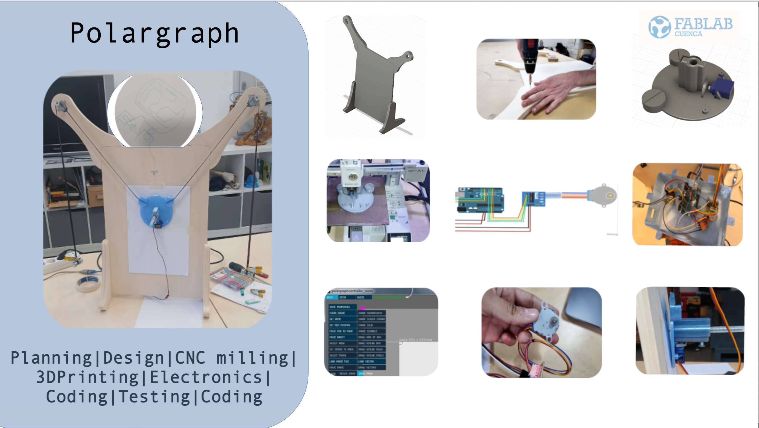
When we started thinking about the kind of machine we wanted to build, we knew we were looking for something visual, creative, and technically satisfying. A drawing machine — especially a Polargraph — felt like the perfect intersection of mechanics, electronics, and expressive automation.
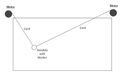
A Polargraph is a type of plotter that draws images by moving a pen suspended between two motors. Instead of moving along traditional X and Y axes, the pen's position is determined by adjusting the length of the cords attached to each motor, relying on gravity and tension to guide its path. It's a interesting system capable of producing intricate and beautiful results.
We chose to build a Polargraph for several reasons. First, it combines mechanism + actuation + automation + application — all of which are essential goals in this assignment.

What is a Polargraph?
A polargraph is a type of drawing robot that operates using two motors mounted at the top corners of a vertical surface. These motors control the length of cords that hold a pen suspended between them. By adjusting the length of each cord, the pen moves across the drawing area — not along straight X and Y lines, but in elegant arcs defined by polar geometry. It's often described as an Etch-a-Sketch powered by gravity.
A Brief History
The polargraph concept has roots in early engineering plotters and analog drafting tools. However, the term "Polargraph" — and the open-source community that formed around it — was popularized by Sandy Noble around 2011. His work made this machine accessible and modular, allowing makers around the world to experiment with generative art, motion control, and physical computation.
Since then, it has become a favorite among educators, digital artists, and engineers as a bridge between code and creativity.
Why this machine?
We were also inspired by the fact that Fab Lab Cuenca has been exploring the idea of including a polargraph as part of their collection of educational demo modules. That interest helped influence our decision, and it gave our project a meaningful direction — contributing something useful and potentially reusable for outreach and teaching.
References & Research
During the early stages of the project, we explored a number of tutorials, articles, and existing builds to understand the different approaches to building a polargraph, and to collect inspiration for our own design. These included:
- Wikipedia – Polar Plotter
- Sandy Noble's Polargraph Drawing Machine – YouTube
- Original Polargraph Instructable
- IVProjects GitHub – Engineering Projects
- Minimal polargraph build – YouTube
- Compact plotter demo – YouTube
- Creative drawing examples – YouTube
- Processing-controlled polargraph – YouTube
- YouMagine – Polargraph Model
- Tinkercad – Polargraph Projects
- Cassiopeia Studio – Polargraph Gallery
This documentation reflects the process we followed to bring it to life: from mechanical design and electronic wiring to firmware development and software calibration.
Electronics & Wiring
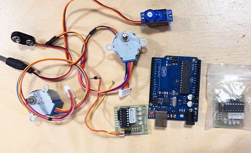 Our Polargraph uses two 28BYJ-48 stepper motors with ULN2003 driver boards, an Arduino UNO R3, and a servo motor to lift and lower the pen.
Components Used
- 2 × 28BYJ-48 stepper motors (5V DC)
- 2 × ULN2003 driver boards (for the stepper motors)
- 1 × Arduino UNO R3 (main controller)
- 1 × Tower Pro SG90 servo motor (for pen lift)
- 1 × 5V 2A power supply (for external power)
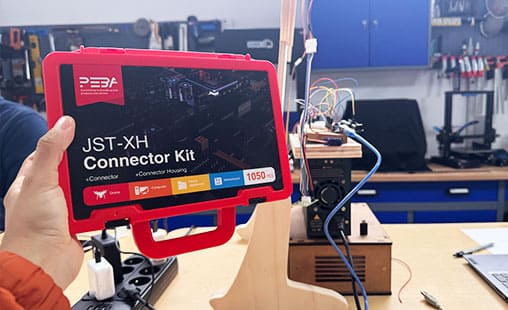
- JST-XH connector kit (with crimp terminals and housing)
- Dupont jumper wires
- Breadboard (used temporarily for testing)
- Soldering iron and crimping tools
Wiring & Setup
We started by testing the stepper motors individually using the ULN2003 driver boards. The ULN2003 has 4 control inputs (IN1–IN4) and a 5-pin output connector that connects directly to the stepper motor. For each motor, we assigned four digital pins from the Arduino.
Our final pin configuration looked like this:
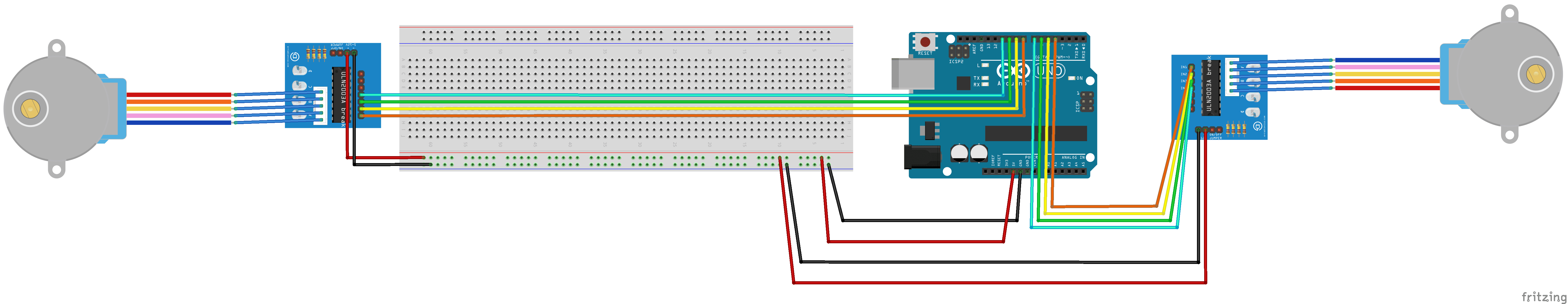 Stepper Motor A (Left):
- IN1 → Pin 4
- IN2 → Pin 5
- IN3 → Pin 6
- IN4 → Pin 7
- IN1 → Pin 8
- IN2 → Pin 9
- IN3 → Pin 10
- IN4 → Pin 11
 The red wire from the motor is VCC and connects to 5V.
For the servo motor, we connected the signal pin to Arduino pin 13, the red wire to 5V, and the brown (or black) wire to GND.
Testing & Troubleshooting We ran a basic Arduino sketch to move each stepper motor and the servo independently.
#include < Stepper.h >
#include < Servo.h >

#define STEPS 2048 // pasos reales por vuelta

Stepper motorA(STEPS, 4, 5, 6, 7);  // M1
Stepper motorB(STEPS, 8, 9, 10, 11);  // M2

Servo penServo;

void setup() {
	motorA.setSpeed(100);
	motorB.setSpeed(100);

	penServo.attach(13);

	Serial.begin(9600);
	Serial.println("All ready...");
}

void loop() {
	Serial.println("Engines move forward");
	motorA.step(1024);
	motorB.step(1024);
	delay(500);

	Serial.println("Servo down");
	penServo.write(90);
	delay(1000);

	Serial.println("Engines move backward");
	motorA.step(-1024);
	motorB.step(-1024);
	delay(500);

	Serial.println("Servo up");
	penServo.write(0);
	delay(1000);
}
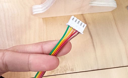
We decide to do a extra step to extend the cables, from the motors to the electronics at the back of the machine, we created custom cable extensions using JST-XH connectors. These connectors snapped securely into place and allowed for quick disconnection during assembly or testing.
Programming & Firmware
 With the electronic components wired and successfully tested, the next step was to give the machine the ability to interpret commands and move as intended. This meant flashing the appropriate firmware onto the Arduino and making the necessary modifications for our hardware setup.
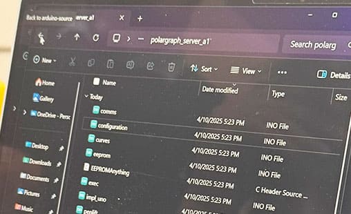
We used the open-source firmware called polargraph_server_a1, which is specifically designed to drive Polargraph drawing machines. This firmware handles serial communication with a Processing-based controller, calculates the steps needed to position the gondola, and moves the motors accordingly.
With the electronic components wired and successfully tested, the next step was to give the machine the ability to interpret commands and move as intended. This meant flashing the appropriate firmware onto the Arduino and making the necessary modifications for our hardware setup.
We used the open-source firmware called polargraph_server_a1, which is specifically designed to drive Polargraph drawing machines. This firmware handles serial communication with a Processing-based controller, calculates the steps needed to position the gondola, and moves the motors accordingly.
How the Firmware Works
The firmware is modular and consists of multiple .ino files, including:
polargraph_server_a1.ino– Main entry point and serial parserimpl_uno.ino– Implementation for Arduino UNO, including stepping logicconfiguration.ino– Motor pin definitions and driver selectioncomms.ino,penlift.ino,exec.ino– Logic for processing commands
Firmware Configuration Changes
1. Specify the Microcontroller
#ifndef MICROCONTROLLER
#define MICROCONTROLLER MC_UNO
// #define MICROCONTROLLER MC_MEGA
#endif
2. Enable the ULN2003 Driver
#define UNL2003_DRIVER3. Disable Adafruit Motor Shield
// #define ADAFRUIT_MOTORSHIELD_V1
// #include <AFMotor.h>
Motor Configuration
#define motorPin1  4
#define motorPin2  5
#define motorPin3  6
#define motorPin4  7
#define motorPin5  8
#define motorPin6  9
#define motorPin7 10
#define motorPin8 11

#define HALFSTEP 8
AccelStepper motorA(HALFSTEP, motorPin1, motorPin3, motorPin2, motorPin4);
AccelStepper motorB(HALFSTEP, motorPin5, motorPin7, motorPin6, motorPin8);
Control Platform
Once the firmware was successfully uploaded and responding to basic commands, we moved on to setting up the Polargraph Controller, a Processing-based software that acts as the user interface for controlling the machine. This platform is essential for sending drawing commands, moving the gondola manually, lifting or lowering the pen, uploading artwork, and calibrating the motion scale of the machine.
Installing the Controller
We open the folder "controller" from the .zip of polargraph_server_a1, from its official GitHub repository. It's written in Processing, so we made sure to install Processing first.
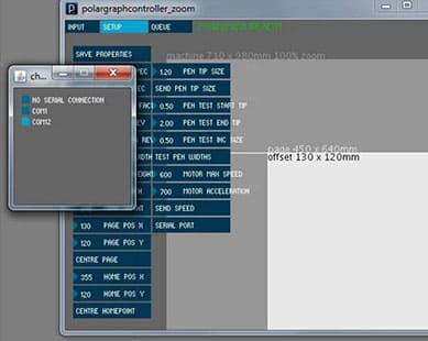
After launching the controller.pde sketch, we selected the correct serial port for our Arduino UNO and clicked "Connect".
Immediately, we saw a confirmation in the console: POLARGRAPH ON! READY!
This confirmed that the controller had successfully connected to the firmware running on the Arduino.
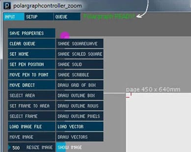
First Tests: Movement Direction
The interface has a set of controls to manually move the gondola. We tried clicking the purple dot in the drawing area (used for pen movement), expecting the motors to lower the gondola straight down. Instead, we observed that both motors moved in the same direction, which could caused the gondola to drift diagonally instead of vertically.
To solve this, we modified the firmware logic by inverting the direction of one motor in the code. This allowed us to keep all the wiring clean and without making hardware changes.
Once that fix was applied, we uploaded the firmware again, restarted the controller, and repeated the test. This time, the motors moved in different dirrections as expected. This confirmed that motor synchronization and direction were correct.
Configuring Machine Settings
The next step was to configure the physical parameters of the machine within the controller. These include:
- Steps per revolution (stepsPerRev) – how many steps the motor needs to complete one full turn.
- Millimeters per revolution (mmPerRev) – how many mm of string are released or retracted with each full rotation of the spool or gear.
- Machine size – width and height in mm, corresponding to the motor mounting points and drawing area.
Pen Lifting Test
The controller includes buttons for "Pen Up" and "Pen Down." When we tested those, we could clearly see the servo motor move in response, confirming that the pen lift mechanism was functioning properly. The motion was smooth and responsive, and didn't require further configuration.
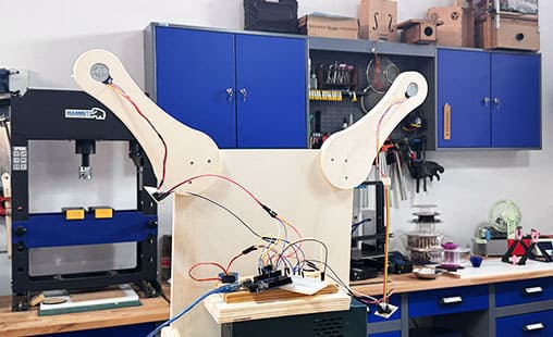
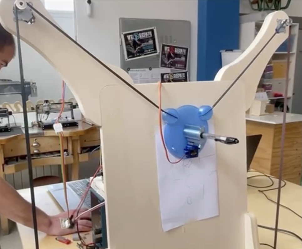
Machine Design & Structure
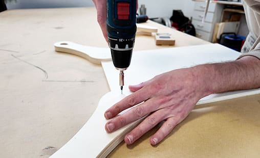
Once our electronics and firmware were ready, we moved on to designing the physical frame of the Polargraph machine. Our goal was to create a stable, portable, and visually clean structure that could hold the motors in position and support the drawing surface securely. We began with a 3D model in Fusion 360, where we designed a stand that would rest on a table and angle the drawing surface slightly backward for better viewing and motor balance.
Mounting the Motors: Each motor was attached directly to the top ends of the structure. We designed holes to match the mounting points of the 28BYJ-48 motors and added a small channel for the motor shaft.
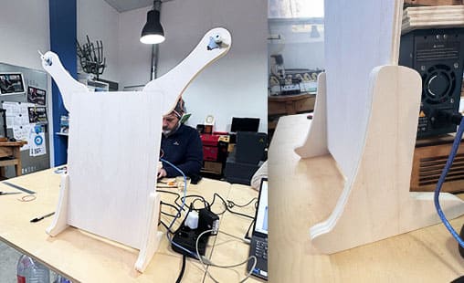
The structure was designed as a freestanding unit with two upward arms to mount the motors and a central flat panel to attach the drawing sheet. The design had to accommodate:
- A wide enough spacing between motors for good drawing resolution.
- Clearance at the bottom so the gondola could move freely across the entire surface.
- Mounting holes for the stepper motors (28BYJ-48), with space for screws and cable routing.
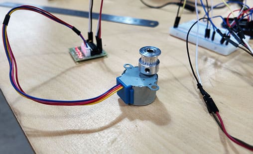
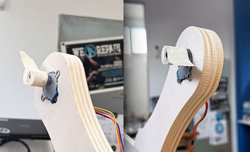
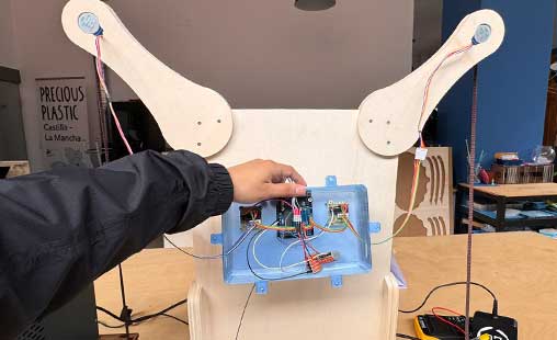
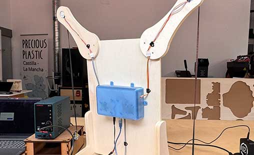
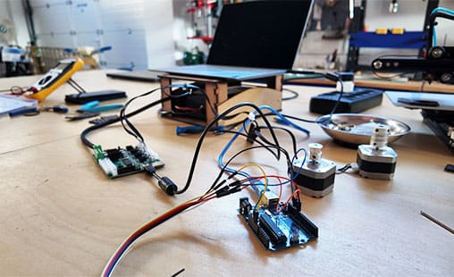
As part of improving the final assembly , we decided to build a custom mount for the electronics: Arduino and drivers behind the structure. During the testing phase, our electronics were spread out on a breadboard, with jumper wires tangled and exposed — as seen in the first image. While this setup worked well for prototyping, it was not ideal for portability or long-term use. To fix this, we created a compact housing mounted directly to the back of the frame. It allowed us to organize and secure all the components. This made the machine much cleaner and safer, preventing cable stress and making the system easier to transport and troubleshoot.
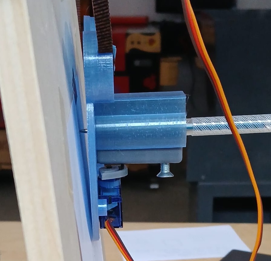
Gondola
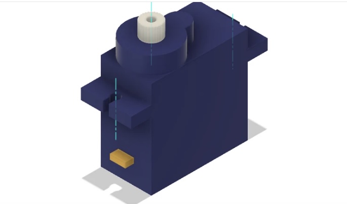
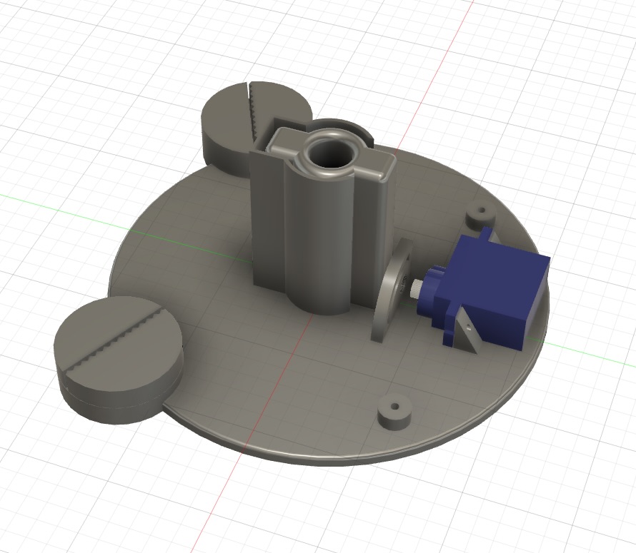
The gondola is a base that is attached to the servo motors using belts or threads. It holds both a pen for drawing and a motor for lifting the pen.For the pen-lifting mechanism, I explored various designs and found this one particularly interesting (link).
I designed the gondola in Fusion 360, focusing on three key elements:
- Designing the pen holder and pen-lifting mechanism
- Positioning and securing the motor
- Attaching the belts that connect to the stepper motors
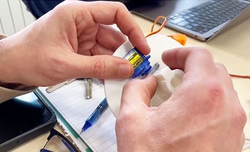
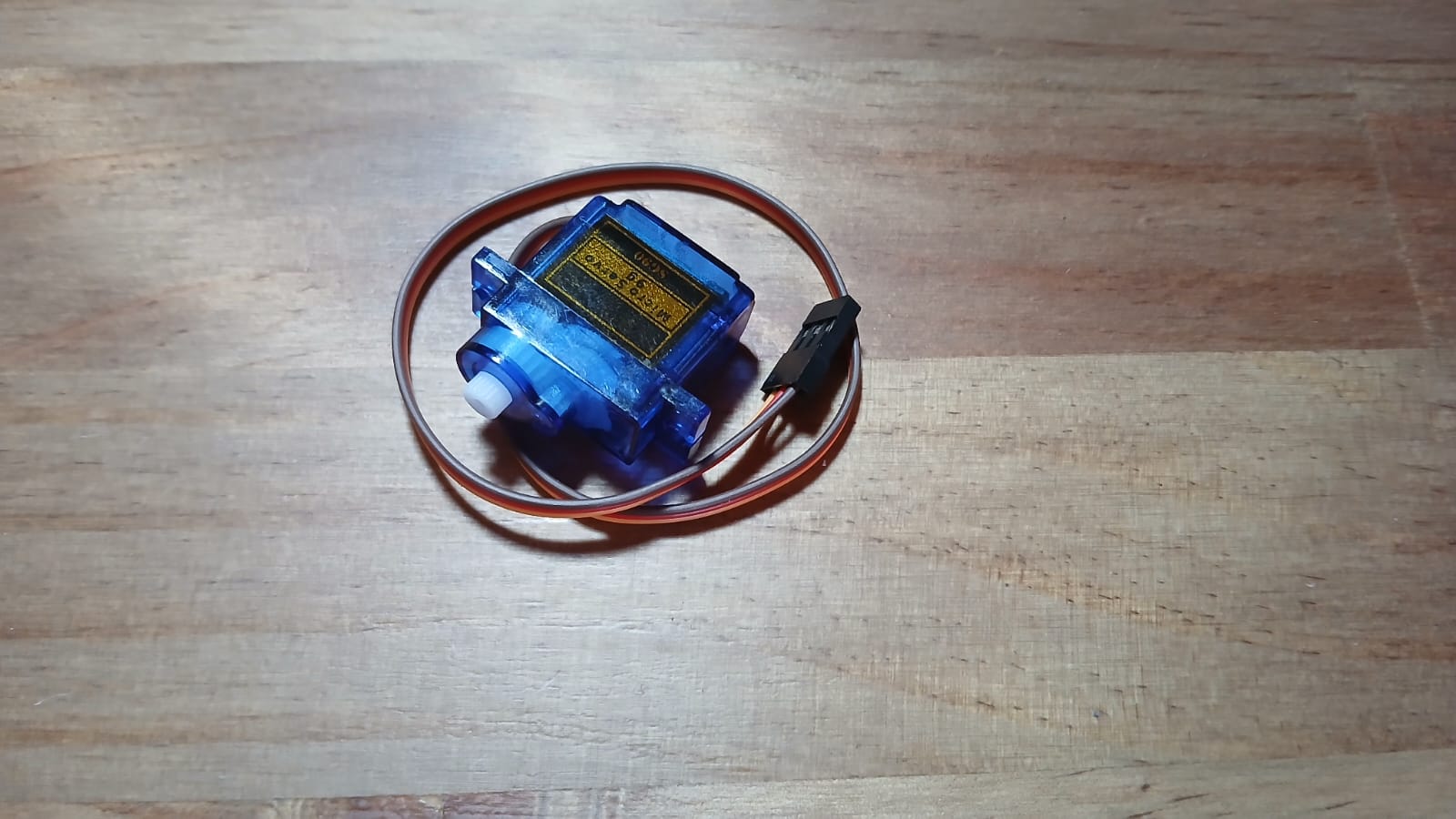
The motor used for lifting the pen is micro servo SG90 from an Arduino kit:
To accurately position the motor within the gondola, I used a Fusion 360
model I found online as a reference
(link)
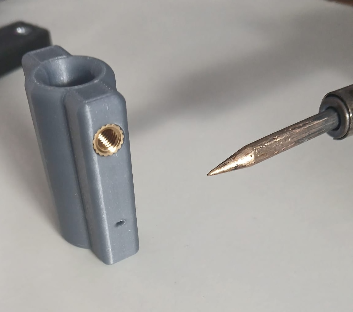
Penholder
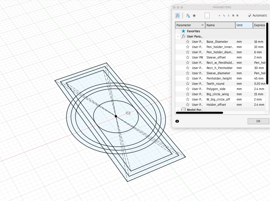
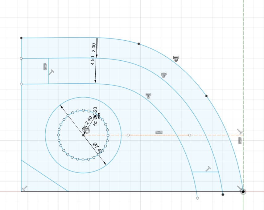
In Fusion 360, I built the components using parametric design, allowing me to easily modify the bodies as needed. Below, you can see the sketch of the pen holder along with its sleeve.
Afterward, I designed and built the pen lifter piece. To do this, I created a gear-shaped outline to cut into the pen lifter piece, allowing it to securely fit onto the motor shaft.
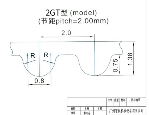
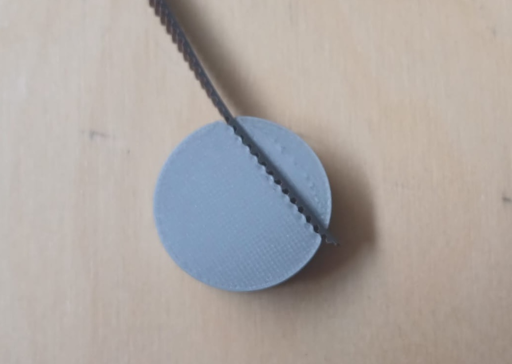
Next, I designed two round belt holders. The groove that holds the belt features a dented pattern, created by drawing a series of triangles to match the tooth profile of a 6 mm wide GT2 timing belt.
Here, you can find a belt fit test.
Finally, here is the finished model. I added fillets to the pen holder to make its insertion into the sleeve smoother and easier.
Then I proceeded to print the gondola in a bambulab 3d printer.
For the pen holder, I added a metal insert, allowing a bolt to securely hold the pen in place.
To determine the correct angle for the servo motor, I used the following Python script and followed its accompanying instructions(link). The angles that best fitted the application were 0 and 87 degrees.
# More details can be found in TechToTinker.blogspot.com
    # George Bantique | tech.to.tinker@gmail.com

    from machine import Pin
    from machine import PWM
    from time import sleep_ms

    def map(x, in_min, in_max, out_min, out_max):
        return int((x - in_min) * (out_max - out_min) / (in_max - in_min) + out_min)

    class GORILLACELL_SERVO:
        def __init__(self, signal_pin):
            self.pwm = PWM(Pin(signal_pin), freq=50, duty=0)

        def rotate(self, angle):
            self.pwm.duty(map(angle, 0, 180, 23, 124))


    servo = GORILLACELL_SERVO(signal_pin=25)

    # The following lines of codes can be tested using the REPL:
    # # To rotate the servo motor to 0 degrees
    # servo.rotate(0)
    #
    # # To rotate the servo motor to 90 degrees
    # servo.rotate(90)
    #
    # # To rotate the servo motor to 180 degrees
    # servo.rotate(180)
    #
    # # To rotate the servo from 0 to 180 degrees
    # # by 10 degrees increment
    # for angle in range(0, 181, 10):
    #     servo.rotate(angle)
    #     print(angle)
    #     sleep_ms(500)
    # # To rotate the servo from 180 to 0 degrees
    # # by 10 degrees decrement
    # for angle in range(180, -1, -10):
    #     servo.rotate(angle)
    #     print(angle)
    #     sleep_ms(500)
Below you can find a video to test of the pen lifting mechanism. There you can see that the right distance is found i.e. as the pen is lifted there is no drawing.
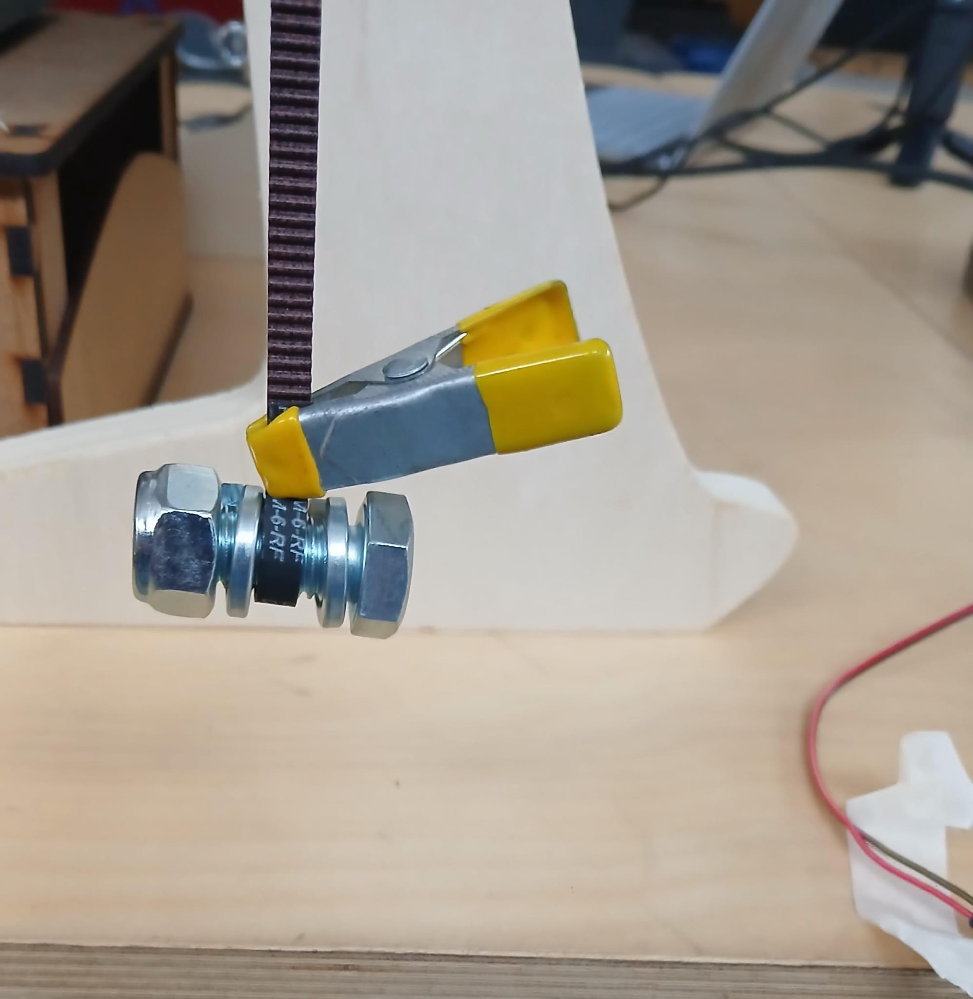
Then we installed the last printed version of the Gondola on to the structure that was built. For this a couple of 6mm belts were attached connecting it to the 2 stepper motors.
We used some nuts and bolts to find the right balance of the gondola on the structure system previously built.
Finally, after full implementation we could see that the pen would touch the paper.
Actuation & Automation
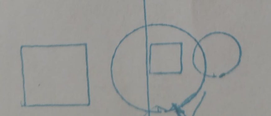
We tested drawing a circle and a square with diameter and sides of 30 mm and 15 mm in Inskape. However, the resulting shapes measured 7.5 mm in diameter for the circle and 5 mm for the square. Increasing the step size by two, we obtained a circle with a 15 mm diameter and a square with a 10 mm side. When we doubled the step size, the dimensions of both objects remained unchanged. Also you can see from the shapes that they height and base of the square differ and taht the circle resembles an ellipse suggesing a further need for calibration
GRBL controller + gcode
After testing the machine with the original Polargraph firmware and Processing-based controller, we decided to try an alternative approach using GRBL, a firmware commonly used for CNC machines and compatible with G-code workflows.
We followed this tutorial
and used the GRBL fork for polar machines from this repository
Step 1 – Flashing the Firmware
We downloaded the modified GRBL firmware and flashed it to the Arduino Uno using the Arduino IDE. Once flashed, we connected the board to Universal G-code Sender (UGS) to check that the firmware was running properly.
Step 2 – Testing Motor Movement and Servo
Inside UGS, we sent simple G-code commands to test the motor movement and the servo lift. We used commands like G0 X... Y... to move the gondola and M3/M5 to raise and lower the pen.
At this stage, we configured the machine parameters using the GRBL console:
$100and$101= 51.2 (steps/mm), calculated from:- 28BYJ-48 motors (2048 steps/rev)
- 20-tooth pulley with 2 mm GT2 belt → 40 mm/rev
2048 / 40 = 51.2
$28 = 640(horizontal motor distance)$29was set based on our actual vertical home position$3(invert motor direction) was adjusted after checking the movement direction
Step 3 – Creating and Sending the G-code
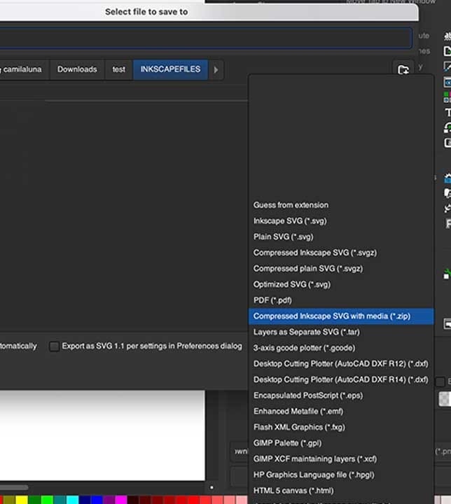
We designed our drawing in Inkscape and used the GRBL Polargraph Inkscape extension from the same GitHub repository to export the vector paths as G-code. This extension converts the design into polar G-code, compatible with our firmware.
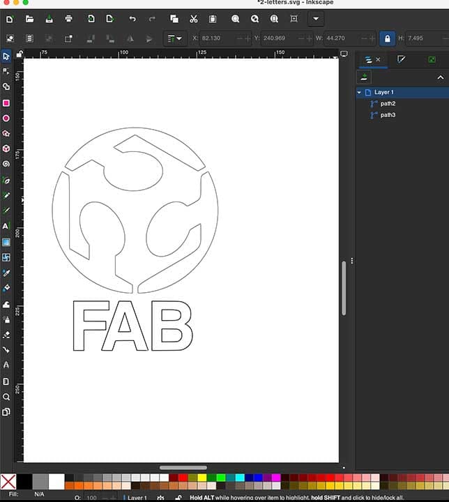
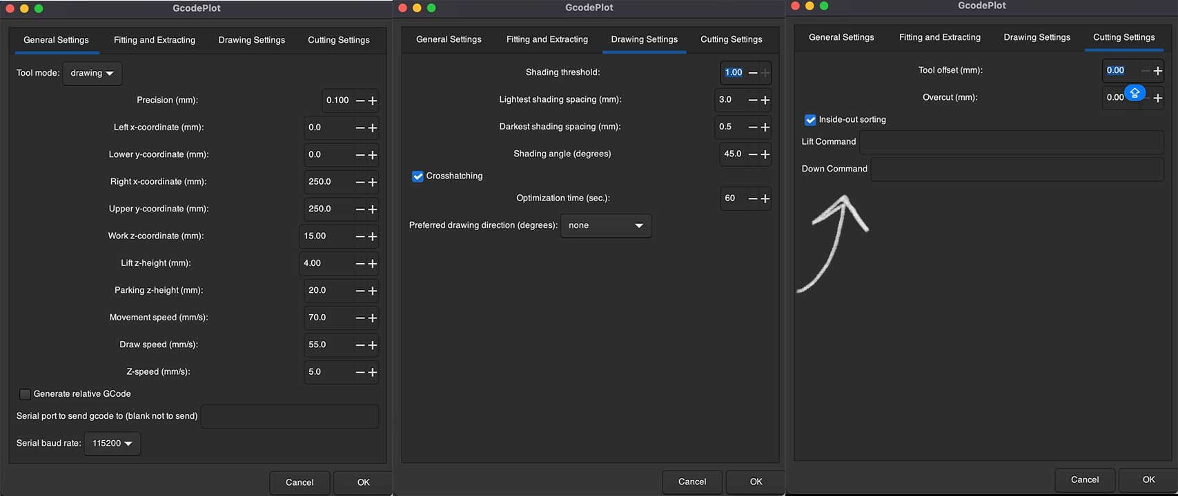
Finally, we loaded the G-code file into UGS, selected the correct COM port, and sent the file to the machine. The drawing process began automatically.
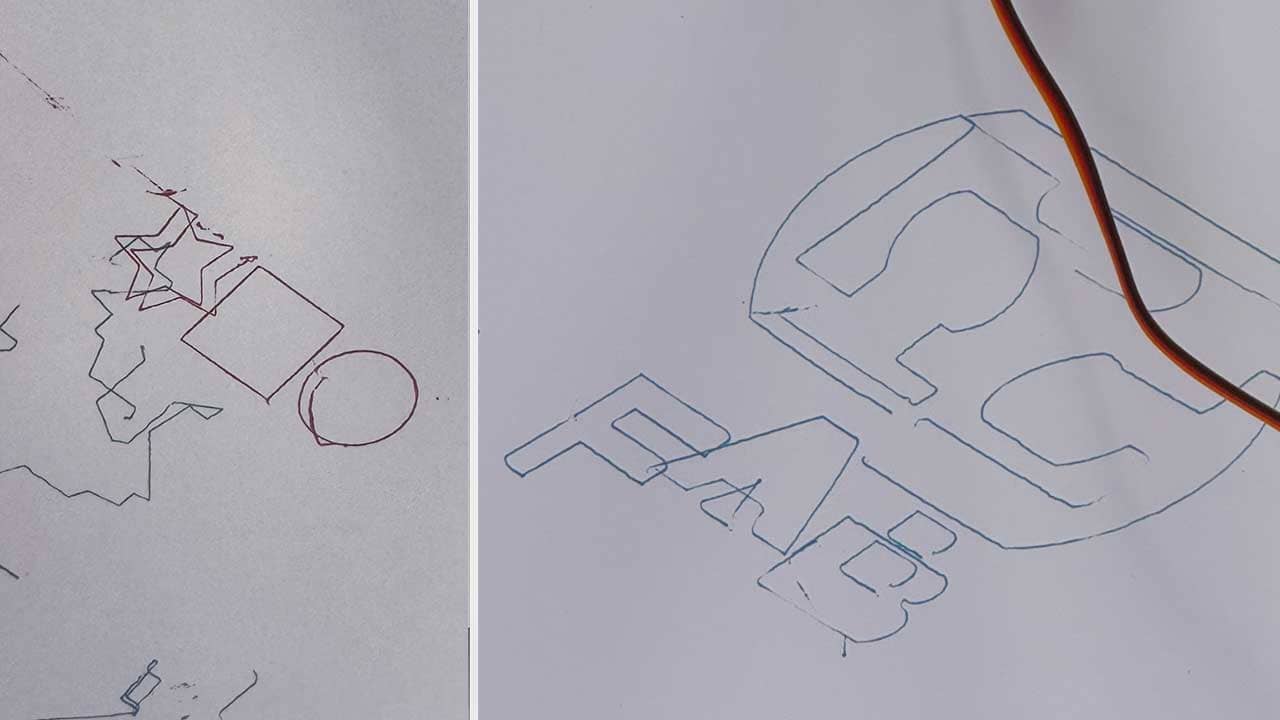
The machine followed the paths, lifted the pen as expected, and completed the commands. However, the output had some visual issues like overlapping lines and distorted proportions. Despite that, the test was successful in helping us explore how a GRBL-based setup could control a polargraph machine from a G-code workflow.
Final Thoughts
We've learned how to integrate mechanical design, electronics, firmware, and software into a single functioning system. The process involved solving real-world problems like motor direction, movement scaling, and cable management — all of which pushed our prototyping and debugging skills.
Links to files (CAD, firmware, controller settings, etc.)
Here is how our project meets the assignment goals:
- ✅ Design a machine that includes mechanism + actuation + automation + application
We designed a Polargraph drawing machine with a custom CNC-cut frame, two stepper motors for actuation, a servo motor for pen control, and Processing software for automation. - ✅ Build the mechanical parts and operate it manually
The machine structure was designed in Fusion 360 and fabricated using a CNC router, as well 3D printing for the rest of the parts. - ✅ Actuate and automate your machine
The electronics and firmware support automated movement and pen control. Drawing automation was completed after gondola testing. - ✅ Document the group project and your individual contribution
All design files, firmware changes, wiring diagrams, and step-by-step processes are documented clearly. Visuals and reflections are included for each stage of development.
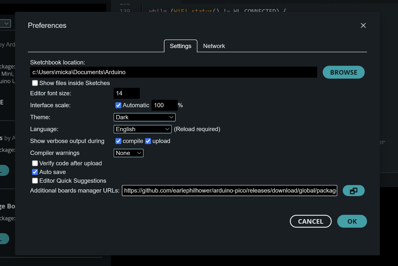
Challenges overcome
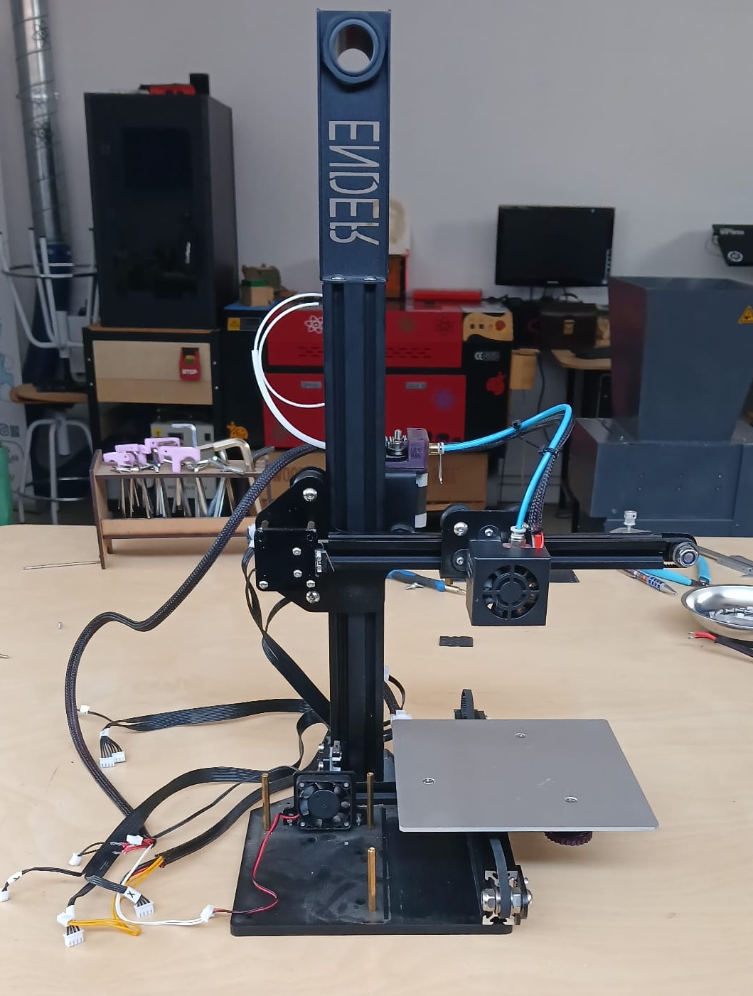
Ender II Firmware installation
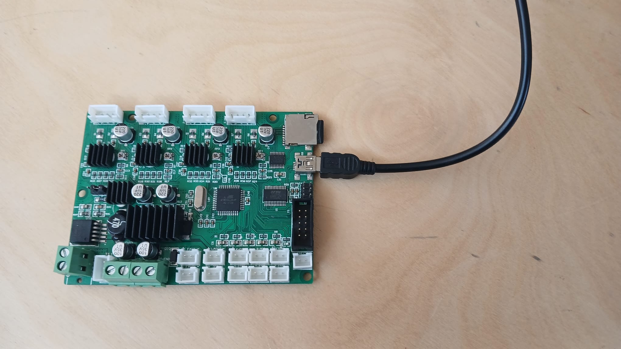
Initially, we attempted to re purpose the controller from an old Ender 2 for our project. I removed the controller board along with some of the motors. Our first task was to install new firmware onto the controller board.
There were several possible versions of the controller board, but we identified ours as the one based on the ATmega1284P. After that, we asked ChatGPT how to install the firmware, and it directed us to this site:
First, we attempted to install the firmware using the Arduino IDE. Unfortunately, the controller was not recognized by the IDE.
Next, we attempted to use an Arduino Uno as a bootloader by connecting its ICSP port to the ISP header on the Ender's controller board. Unfortunately, this method was also unsuccessful, and we were still unable to install the firmware.
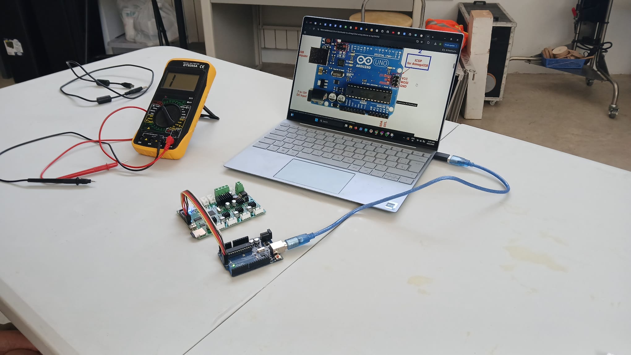
Finally, we decided to use specific pins on the Arduino Uno to connect directly to the ISP header on the Ender's controller board, as shown in the picture below.
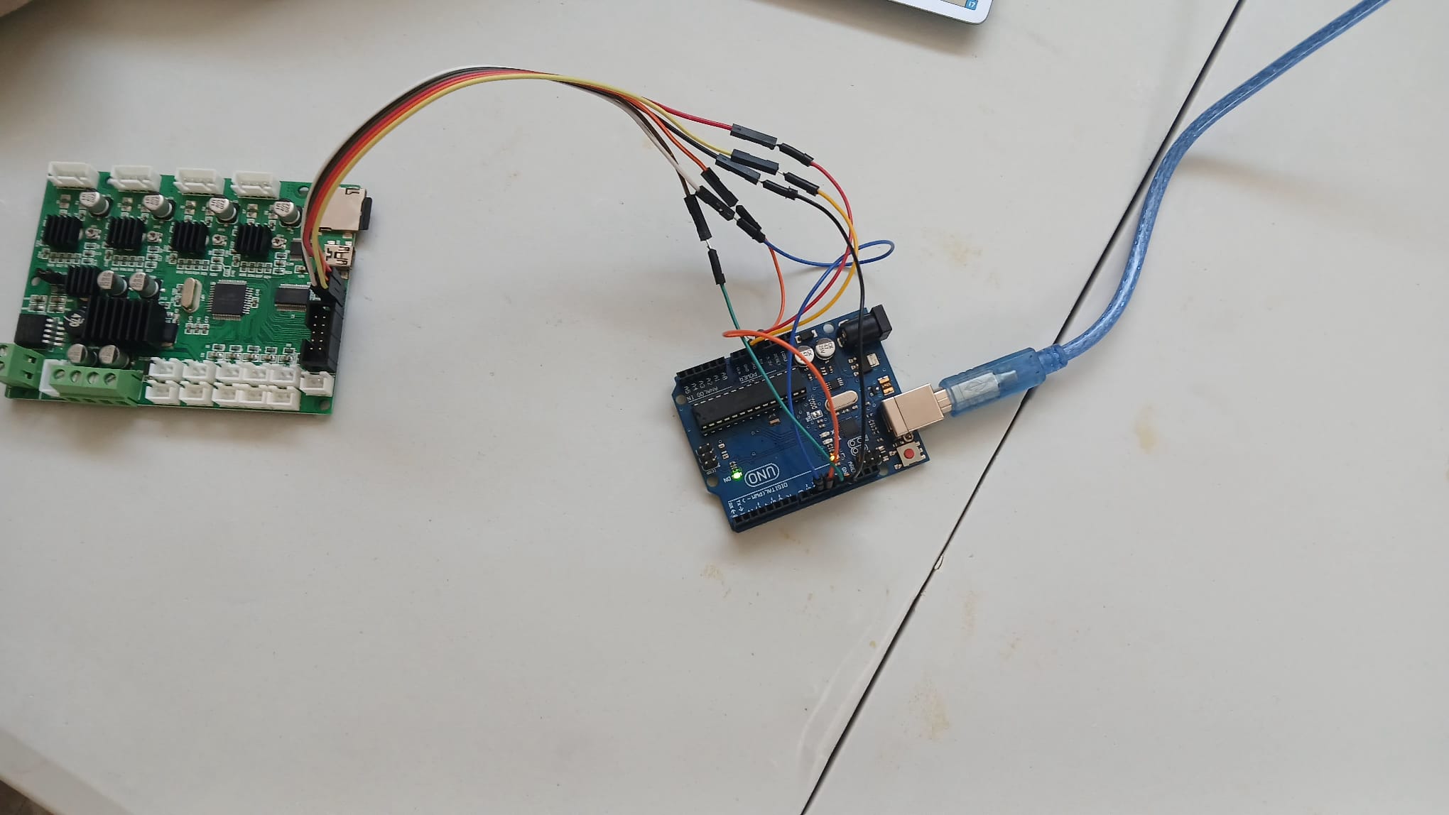
Luckily, this method worked. The issue earlier was likely due to a mismatch between the ISP pins on the Arduino and those on the Ender's controller board.
The steps from the IDE side to install the software were:
Here the board firmware was downloaded from:
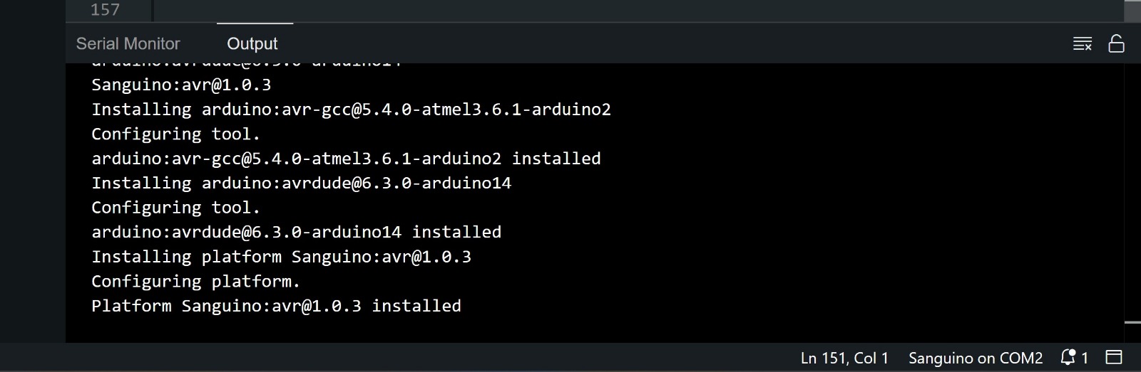
Thereafter, we tried to install a software to see if we could blink a led.This took a while as the information in regards to which pin was connected to the pin was not available. We had to install the program through arduino using Arduino as a programmer.
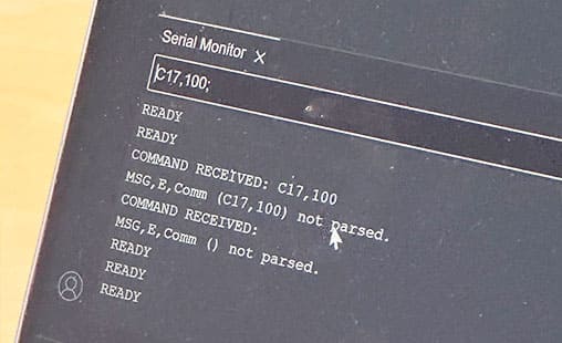
After uploading the Polargraph firmware to the Ender 2 board and attempting to test motor control through the Serial Monitor, we confirmed that the firmware was compiling and uploading correctly. However, despite receiving commands, the motors did not respond. These issues, along with limited documentation for the Ender 2's exact hardware setup, made it difficult to ensure reliable communication between the microcontroller and motor drivers. For this reason, we decided to switch to the Arduino, for easier debugging and testing in a more predictable environment.
B.O.M.
| Name | Description | Units | Price/Unit |
|---|---|---|---|
| 1. | 28BYJ-48 stepper motors (5V DC) | 2 | 1,06 x 2 |
| 2. | ULN2003 driver boards (for the stepper motors) | 2 | inc. above |
| 3. | Arduino UNO R3 | 1 | 2.64 |
| 4. | Tower Pro SG90 servo motor (for pen lift) | 1 | 1.35 |
| 5. | 5V 2A power supply (for external power) | 1 | 1.76 |
| 6. | JST-XH connector kit (with crimp terminals and housing) | 1 | 2.35 |
| 7. | Dupont jumper wires | 1 | 1.96 |
| 8. | GT2 distribution belt | 1 | 1.26 |
| 9. | PLA filament (40 grams) | 1 | 0.80 |
| Total | 14.24 | ||
- © FabLab Cuenca 2025
- Design: HTML5 UP