For this week assignment the objectives were:
- group assignment:
- send a message between two projects
- individual assignment:
- design, build, and connect wired or wireless node(s) with network or bus addresses and local input &/or output device(s)
1. Group Assingment
The full group assignment can be found here
For the group assignment I summarized some of the most common types of serial communication, one of which UART was tested in the lab.
Serial Communication
Serial communication involves sending data sequentially, one bit at a time, over a single channel or bus (Wikipedia). This differs from parallel communication, where multiple bits are transmitted simultaneously across several channels. The summary below is based on information from Wikipedia, Circuit Basics, and these YouTube videos (Electronoobs,Rhode & Schwarz).
One of the key advantages of serial communication is its wiring simplicity, as it requires fewer channels. However, since data is transmitted one bit at a time, synchronous protocols need a clock pulse for each bit, which may reduce data throughput compared to parallel methods. Serial communication is categorized as either synchronous or asynchronous depending on whether a shared clock signal is used to synchronize data transfer.
Some Key Characteristics of Serial Communications:
- Levels: Voltage levels represent binary values — 0 (low) and 1 (high).
- Timing: Defines how often and how quickly bits are transmitted.
- Framing: Organizes bits into message units.
- Protocol: Specifies what data is sent and under which conditions.
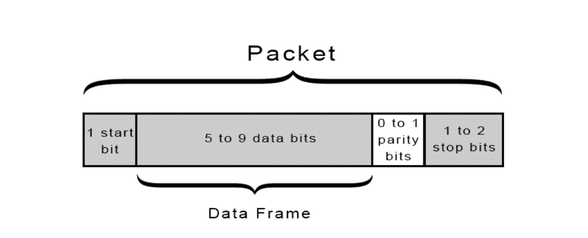
UART (Universal Asynchronous Receiver/Transmitter)
UART is an asynchronous serial protocol that enables communication between devices using two elements:
- Tx (Transmit) – Sends data
- Rx (Receive) – Receives data
It is important to ensure that Rx and Tx work with the same settings/parameters including:
- Baud Rate: Sets the speed of data transmission.
- Start Bit: Signals the start of transmission with a low signal after an idle high state.
- Data Bits: Indicates how many bits make up each data unit (typically 5 to 9).
- Stop Bits: Signals the stop of the transmission with a high signal to return to an idle state.
Below you can find a schematic of a UART transmission packet.
Advantages:
- Uses only two wires (one for sending the data + ground reference).
- No clock signal required.
- Widely used in embedded systems.
Disadvantages:
- Limited to 5-9 bit dataframes.
- Doesn’t support communication with multiple controllers or receivers natively.
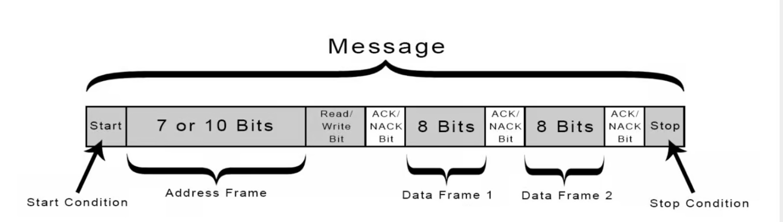
I2C (Inter-Integrated Circuit)
I2C is a synchronous protocol that allows multiple controllers and receivers to share a two-wire communication bus (+ ground) which includes:
- SDA (Serial Data) – Carries the data
- SCL (Serial Clock) – Synchronizes the data transfer
Messages are broken into frames, each containing the receiver’s address, and are framed by start and stop conditions. Both the transmitter and receiver need to know the number of bits that will be sent and the clock frequency. Each receiver has specific receive address and hence is a one to one communication. In the transmission packets there might be some parts dedicated to acknowledge (see below) the correct reception of data.
Advantages:
- Only three wires required (SDA,SCL and ground)
- Can achieve speeds of 400kb/s-3.5Mb/s (depending on the mode)
- Supports multiple controllers and receivers
- Popular and well-supported protocol
Disadvantages:
- Slower than SPI
- 8-bit data frame limit.
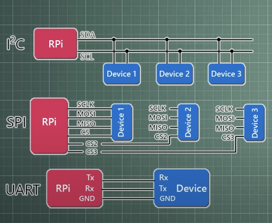
SPI (Serial Peripheral Interface)
SPI is a synchronous communication protocol that enables continuous and simultaneous data transfer between a controller and receiver. Unlike I2C and UART, SPI doesn’t rely on predefined start/stop bits and can transmit any number of bits without interruption.
SPI Lines:
- MOSI (Controller Out, Receiver In) – Transfers data from the controller to the receiver
- MISO (Controller In, Receiver Out) – Transfers data from the receiver back to the controller
- SCLK (Serial Clock) – Provides the timing signal from the controller
- SS/CS (Receiver Select/Chip Select) – Used by the controller to choose the receiver device
To send new data the controller will set the Chip select low and then send the MOSI clock and MOSI information. For each device connected a CS connection is needed. This type of communication is full duplex meaning that both transmitter and receiver can send data at the same time.
Advantages:
- No start/stop bits; enables continuous data flow
- Simpler than I2C—no addressing mechanism
- Higher data rates—typically nearly twice as fast as I2C
- Full-duplex communication (send and receive at the same time)
Disadvantages:
- Requires four wires + ground.
- No acknowledgment to confirm data receipt.
- Lacks built-in error detection like UART’s parity bit.
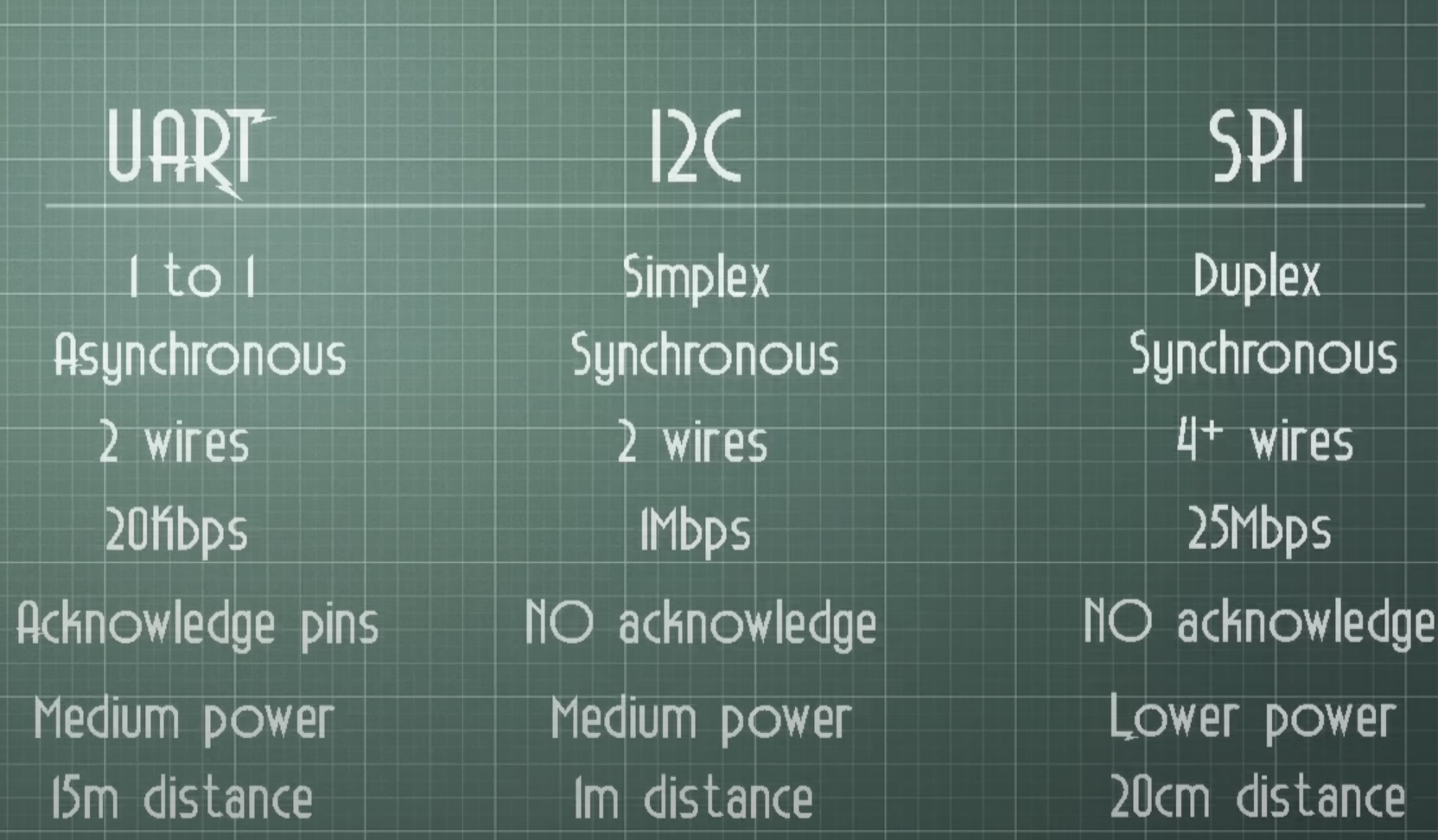
Below is a summary of the characteristics of each communication system and hierarchies.
2. Individual Assigment
I will begin by describing the communication components of my final project. Then, I will tailor this week’s assignment to address some of their specific requirements. All communications. are wireless.
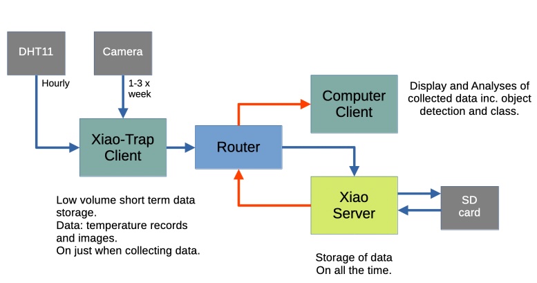
The communication system is divided into three main parts (seem image below):
A camera trap: This module includes a XIAO ESP32 S3 Sense with Wi-Fi capabilities, connected to a small camera module OV 26040 and a DHT11 temperature and humidity sensor. It functions as a client, collecting temperature data and images. Once the data is transmitted to the XIAO ESP32 server, it is deleted from the memory to conserve space. To save energy, data transmission will occur only at specific intervals.
Server: This component consists of another XIAO ESP32 S3 (no camera) that receives pictures and sensor data from an array of camera traps deployed in a given area. It functions as a server that listens for incoming transmissions.The server is connected to an SD card to store the incoming data temporarily. Once the data has been successfully forwarded to a computer client, it is erased from local storage. Additionally, the server includes an OLED display to show the most recently sent file—both image and accompanying text.
Computer Client: This is a client (local computer) that receives both images and text files(temperature), processes it, and presents it through a user-friendly interface.
So the requirements for this are and access point in this case my home router, 2 clients (Xiao sense and Computer) and a server (Xiao).
PCB boards used
Camera Trap board
For the Camera Trap client I used the PCB I produced in week 8 that had the goal and was used for testing the dc motor that week. For this week, I needed pins for and OLED and a temperature sensor.
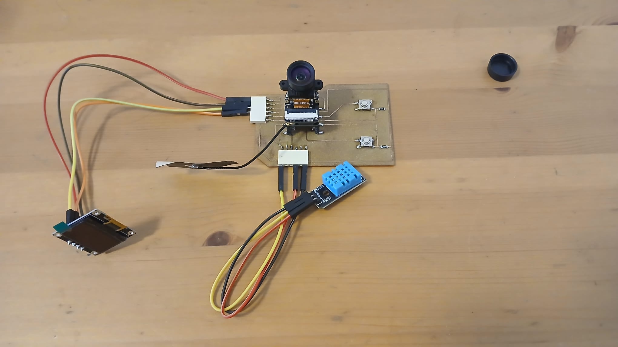
Hence I needed two SDA and one SCL pin. I wanted to use an OLED here just for debugging as I have only one computer where to connect Thonny and could not see what goes on in the two Xiaos at the same time. Because of this and because I wanted to see it in action, I remapped the pin 1 and 2 to SDA and SCL. I ask ChatGPT something along the lines of: Please remap pins 1 and 2 to SDA and SCL but I forgot to record the exact command I gave it. Below, you can find the modified code.
# This sets pin one and two as SDA and SCL
# Initialize I2C on GPIO1 (SDA) and GPIO2 (SCL)
i2c = I2C(0, scl=Pin(2), sda=Pin(1), freq=400000)

print("I2C devices found:", i2c.scan())
oled = ssd1306.SSD1306_I2C(128, 64, i2c)
Later, in the regional review, Luis the instructor of Fab Lab “A Industriosa” located in Vigo, told us that one could use the same pins to run multiple Oleds and DHT11 sensors. Important for future projects!
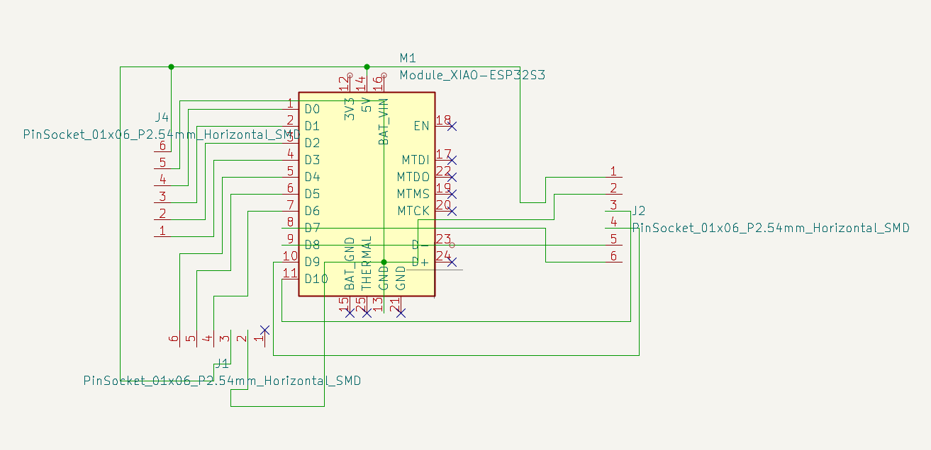
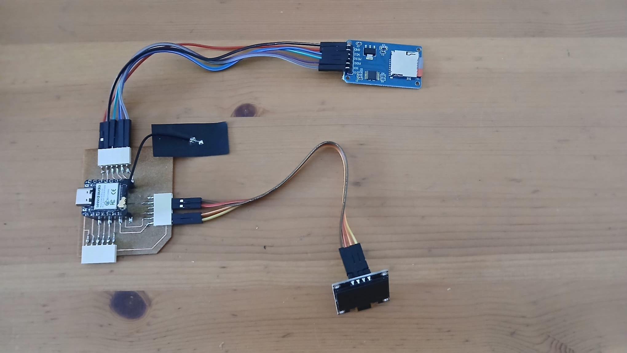
Xiao’s server board
Similarly, I milled a board for my Xiao server. The first socket will connect to a small button PCB board that has 4 buttons (to come). A couple for scrolling up and down for option within a mode and a couple for scrolling between modes on a Oled display. The second socket will connect to an OLED display while the third will connect to a SD card to store text and image files.
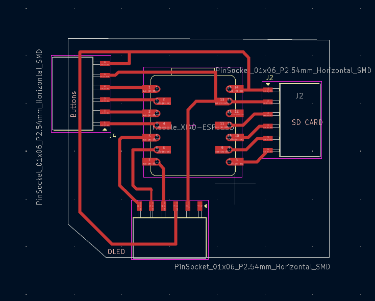
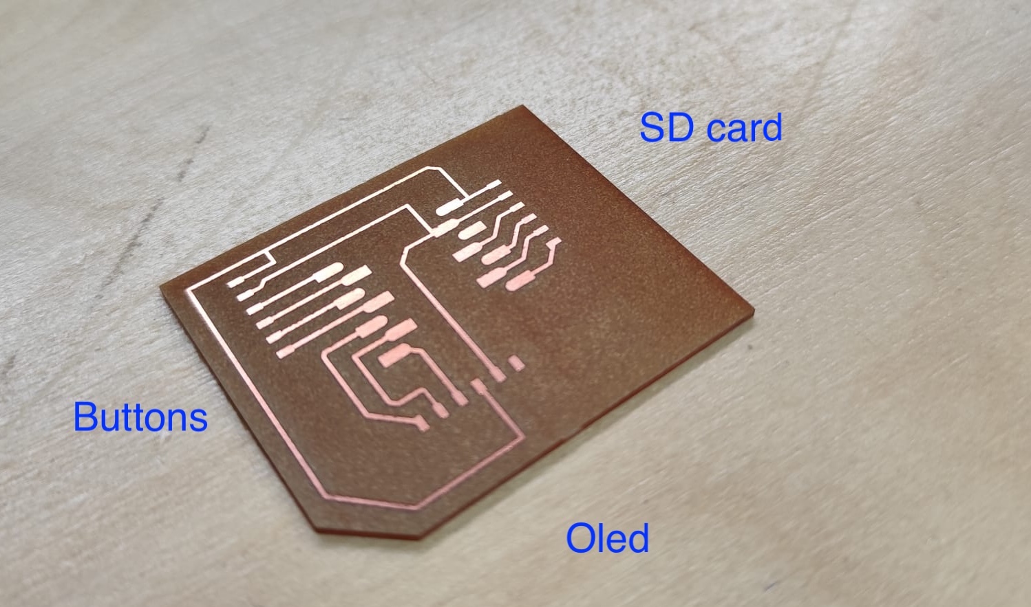
Here you can see the board and components
For the SD card reader module I used the following module ANGEEK XF0049X5:
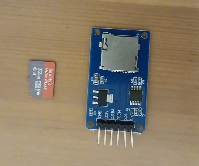
I viewed a tutorial by TechToTinker (link ) in which he demonstrates how to interface with an SD card using a module that employs Serial Peripheral Interface (SPI) technology. SPI is a synchronous communication protocol that facilitates data exchange between devices. The module in question includes the use of following pins:
- GND
- VCC (supports upto 5V)
- MISO: for the SPI Controller Input Receiver Output pin
- MOSI: for the SPI Controller Output Receiver Input pin
- SCK: for the SPI Serial Clock pin
- CS: for the Chip Select pin
Note that the actual sdcard itself needs to be formatted for FAT. Fat this stands for: File Allocation Table—it’s a file system architecture originally developed by Microsoft for MS-DOS, and it’s one of the oldest and simplest types of file systems still in use today(ChatGPT).
I also found a resource from a former Fab Academy student who provided a detailed pin out sheet for the Xiao ESP32 S3. The document can be accessed (here). The code connecting the board to the SD card reader is below.
I dowloaded the sdcard module and save it in the root directory of my XIAO board. A copy of the library can be found here. The remaining libraries required for the setup are standard modules included with MicroPython. Note that the sdcard library is a wraper for other libraries.
# First you need to assign the SPI pins. I used the ones suggested above.

import os
from machine import Pin, SoftSPI
from sdcard import SDCard

# Pin assignment:
# MISO -> GPIO 8
# MOSI -> GPIO 9
# SCK  -> GPIO 7
# CS   -> GPIO 44

spisd = SoftSPI(-1, miso=Pin(8), mosi=Pin(9), sck=Pin(7)) ## Here  specifying the pins for the SPI connection.
sd = SDCard(spisd, Pin(44)) # this is the pin for the chip select.
vfs = os.VfsFat(sd) # this creates a virtual file system
os.mount(vfs, '/sd') # mounts the sd card

# Note if you wanted to go back to the root file system you need to type: os.chdir('/')
The TechToTinker video demonstrated the use of the micropython os module that I will be using a lot in my project for file management. Below I show some code in the context of my project.
A bit on file management
You can use the following code to estimate the free memory available:
fs_stat = os.statvfs('/sd')
total = fs_stat[0] * fs_stat[2]
free = fs_stat[0] * fs_stat[3]

print("Flash storage total (bytes):", total)
print("Flash storage free (bytes):", free)
In this reference, you can find information about the os module, which allows for the management of a file system. some examples below.
# Here we create and write the file

f = open(filename+str('.txt'),'w')
f.write(filename+" "+temp_readingF())
f.close()

# Here we read and print the content

f = open(filename+str('.txt'), 'r')
print(f.read())
f.close()

# Here we append a new temperature reading using functions to read and create time stamp (see below)

time.sleep(1)
f = open(filename+str('.txt'), 'a')
add_new_reading=Trap_noF(1)+"_"+time_stampF()
f.write('\r\n'+add_new_reading+" "+temp_readingF())
f.close()

# Here we read and print the content again

f = open(filename+str('.txt'), 'r')
print(f.read())
f.close()

print('Root directory:{}'.format(os.listdir()))
Implementing Wireless Networking
Below, I adapt a code example from Week 6 to establish communication between two XIAO boards.
1. Camera-Trap Client
First, I will create a text file that stores data from the DHT11 sensor. The filename will include the date and time of its creation, as well as a unique ID for the camera trap. For a specified amount of time the board takes temperature readings, which will be appended to the file. The new file will replace the old one for now… This process will repeat iteratively. Below, I will break the code in parts to make to make it more understandable.
Here I load modules and define the temperature sensor pin,
# Libraries needed
import network
import socket
import time
import ssd1306 # Oled wrapper module
from machine import Pin, I2C
import dht
import camera

# Mapping DHT11 pins
dht_sensor = dht.DHT11(Pin(5))
then I developed or package someones else code in functions.
# Labeling Trap
def Trap_noF(number):
    Trap_no = "Trap" + str(number)
    return Trap_no

# Function for reading temp
def temp_readingF():
    dht_sensor.measure()
    temp = str(dht_sensor.temperature())
    return temp

# Function for creating a time stamp
def time_stampF():
    correction_m = ""
    if time.gmtime(time.time())[4] <= 9:
        correction_m = "0"
    correction_s = ""
    if time.gmtime(time.time())[5] <= 9:
        correction_s = "0"
    time_string = str(time.gmtime(time.time())[1]) + " " + str(time.gmtime(time.time())[2]) + " " + str(time.gmtime(time.time())[3]) + " " + correction_m + str(time.gmtime(time.time())[4]) + " " + correction_s + str(time.gmtime(time.time())[5])
    return time_string

# Function for measuring temperature at different times and appending it to a file of temperature readings
def Temperature_readingsF(filename,iterations,frequency,trap_number) :
    for x in range(0, iterations):
        file_temp_readings = open(filename, 'a')
        add_new_reading=Trap_noF(trap_number)+" "+time_stampF()
        file_temp_readings.write('\r\n'+add_new_reading+" "+temp_readingF())
        file_temp_readings.close()
        time.sleep(frequency)

# Function for taking a picture -- someone else code (https://www.youtube.com/watch?v=TDgM8eMTpIw)
def Photo_shootF() :
    try:
        print('Taking a photo')
        camera.init()
        buffer = camera.capture()
        print(len(buffer))
        file_path = "captured_image.jpg"
        with open(file_path, "wb") as file:
            file.write(buffer)
    except Exception as e:
        print('An issue occurred:', e)
    finally:
        print('Deinitializing Camera and Wifi')
        camera.deinit()
here I set up the OLED screen. See the pin remapping code above.
below, then mcu displays “Client is on” in the OLED and creates a temperature file
# oled initial output
oled.fill(0)
oled.text("Client On", 0, 0)
oled.show()
Photo_shootF() # Taking pictures, sometimes it only worked on the second time.
Photo_shootF()
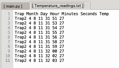
# Generating Temperature File
filename="Temperature_readings.txt"
file_temp_readings = open(filename,'w')
file_temp_readings.write("Trap "+ "Month "+"Day "+"Hour "+"Minutes "+ "Seconds "+"Temp") # Header
file_temp_readings.close()
Temperature_readingsF(filename,10,1,2)this is the file produced.
Thereafter, I set up the code for connecting to the router (access point).
# Setup Wi-Fi (static IP)
sta = network.WLAN(network.STA_IF)
sta.active(False)
time.sleep(1)
sta.active(True)
sta.connect('****', '****')
oled.text("Conn2Rout", 0, 10)
oled.show()

while not sta.isconnected():
    print("Connecting to router...")
    time.sleep(1)
Here is the code for connecting to the Xiao server, I had fix the IP address of the Xiao server otherwise if it changes dynamically the camera trap client wont find it.
# Server's static IP and port
addr = socket.getaddrinfo("192.168.1.100", 1234)[0][-1]

# Create a socket, connect to the above address.
client = socket.socket()
client.connect(addr)
print("Connected to server, sending image...")
oled.text("Coned2Server", 0, 20)
oled.show()
Below is where the sending of the files take place. I have set a process variable to decide which data will be send. This variable could be a time dependent variable. For example if today is Monday sent image or if it is 11 am each day, send the temperature file that was collected between that time and the previous day.
# Process one we sent an image process two we sent a text file

process=1

if  process==1:
    print("process 1")
    process_image=1
    client.send(process_image.to_bytes(1,'big'))
    file = open("captured_image.jpg", "rb") # opens file to read bytes
    image_data = file.read(2048) # reads data
    counter=len(image_data) # sets a counter to see how much data has been read
    while image_data:
        client.send(image_data) # sends the data previously read
        image_data = file.read(2048) # reads again
        print(len(image_data))
        counter=counter+len(image_data)
    file.close() # here we close the file.
    oled.text("dat_trfr:"+str(counter), 0, 30)
    oled.show()

if  process==2:
    print("process 2")
    process_text=2
    client.send(process_text.to_bytes(1,'big'))
    file = open("Temperature_readings.txt", "rb")
    temp_data = file.read(2048)
    counter=len(temp_data)
    while temp_data:
        client.send(temp_data)
        temp_data = file.read(2048)
        print(len(temp_data))
        counter=counter+len(temp_data)
    file.close()
    oled.text("dat_trfr:"+str(counter), 0, 30)
    oled.show()


client.close() # closing the connection
oled.text("Img sent",0,50)
oled.show()

print("file sent!")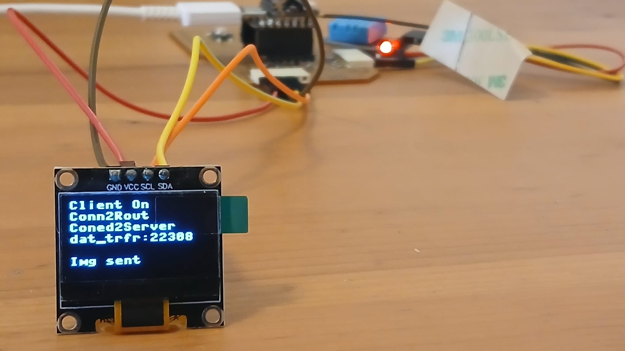
2.Xiao’s Server
Below we set up the code for the server side. Importing libraries, setting up OLED and SD card connections, mounting the SD card and turning led on (“Server on”).
# Modules loading
import network
import socket
import time
import ssd1306
import machine
import os
from machine import Pin, SoftSPI
from sdcard import SDCard

# Set up SPI connection for the SD card
spisd = SoftSPI(-1, miso=Pin(8), mosi=Pin(9), sck=Pin(7))
sd = SDCard(spisd, Pin(44))
vfs = os.VfsFat(sd)
os.mount(vfs, '/sd') # making the card available

# Set up Oled connection
i2c = machine.I2C(0, scl=machine.Pin(6), sda=machine.Pin(5))
oled = ssd1306.SSD1306_I2C(128, 64, i2c)

oled.fill(0) # this will reset the oled
oled.text("Server On", 0, 0)
oled.show()
Below you can find the code for connecting to the router
# Setup Wi-Fi (static IP)
sta_r = network.WLAN(network.STA_IF)
sta_r.active(False) # we make sure to destroy the connection prior to connecting
time.sleep(2)
sta_r.active(True)
sta_r.connect('****', '****') # router credentials
while not sta_r.isconnected():
    print("waiting")
    time.sleep(1)

oled.text("Conn2Rout", 0, 10) # connected to router
oled.show()
Here, we set the connection between the Xiao server and the camera trap client. Note that we fix the IP address of the server which the client already knows!
sta_r.ifconfig(('192.168.1.100', '255.255.255.0', '192.168.1.1', '192.168.1.1'))
print("Server IP:", sta_r.ifconfig()[0])

# Setup server socket
server = socket.socket(socket.AF_INET, socket.SOCK_STREAM)
server.bind(('192.168.1.100', 1234))

server.listen(5) # listening for connections
print("Wait_client")
oled.text("Wait_client", 0, 20)
oled.show()

conn, addr = server.accept()

oled.text("Connected2C", 0, 30)
oled.show()
A pair (host, port) is used for the AF_INET address family, where host is a string representing either a hostname in internet domain notation like ‘daring.cwi.nl’ or an IPv4 address like ‘100.50.200.5’, and port is an integer (source).
SOCK_STREAM – provides sequenced, reliable, two-way, connection-based byte streams (source).
In the code below the first two lines are the bits of information that the client sends so the server so it knows whether the incoming data is text or an image. This allows me to create files with different extensions and route them to different folders.
process_type_bytes = conn.recv(1)
process_type=int.from_bytes(process_type_bytes,'big') # here we translate back to integers
if process_type==1:
oled.text("pro_type"+str(process_type), 0, 40)
oled.show()
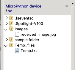
f=open("/sd/Images/received_image.jpg", "wb")
image_chunk = conn.recv(2048)
counter=len(image_chunk)
while image_chunk:
f.write(image_chunk)
image_chunk = conn.recv(2048)
counter=counter+len(image_chunk)
f.close()
oled.text("dat_trfr:"+str(counter), 0, 50)
oled.show()
if process_type==2: # receiving temperature file code simmilar to the one above
...
if process_type==3: # sending an image to the computer client
...
# closing connections
conn.close() # closing connection to other IP
server.close() # closing socket
sta_r.active(False) # killing connection to the router 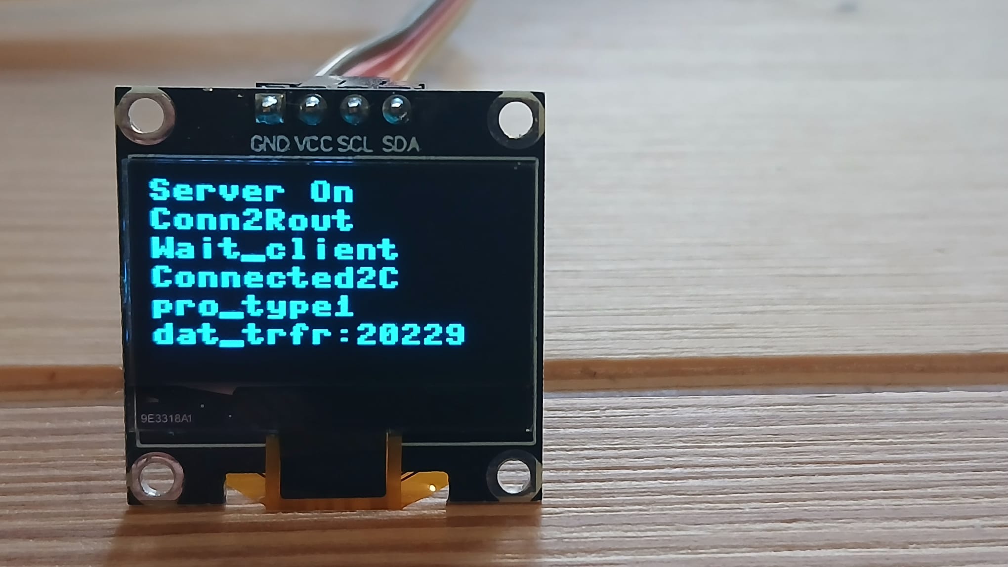
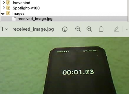
here you can see the image of the filed received stored in the SD card.
3.Computer Client
Finally, I tried based on the code above to develop a computer client
to request files stored in the Xiao server. I spent a lot of time just
trying to connect to the server with no success. Then I ask ChatGPT for
some code that would connect as a client to receive images based on the
Xiao server code above. I still could not connect. Finally, after a lot
of querying the suggestions it provided it pointed out that maybe there
was a problem with the IP addresses. So I looked at the IP addresses of
the router and computer and sent them.
And here ChatGPTs conclusion:
Since your computer’s IP (192.168.0.27) and your router’s IP (192.168.0.1) are in the 192.168.0.x subnet, but your ESP32 is on the 192.168.1.x subnet (192.168.1.100), your computer and the ESP32 are on different subnets. As a result, they cannot communicate directly without proper routing between the two subnets, which your router does not have configured by default.
Something that ChatGPT was suggested which I think is worth remembering is to ping the IP address from the terminal (bash) to see if there was a response meaning that the IP address was in the same network.
import socket
# Set up server details
SERVER_IP = '192.168.0.100' # ESP32 IP address
SERVER_PORT = 1234 # Port number used in ESP32 code
# Connect to the server
client = socket.socket(socket.AF_INET, socket.SOCK_STREAM)
client.connect((SERVER_IP, SERVER_PORT))
# Send process type 3 to request an image
client.send((3).to_bytes(1, 'big'))
# Open file to save received image
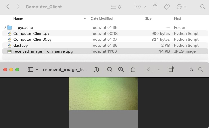
f = open('./Desktop/Python_Scripts/Computer_Client/received_image_from_server.jpg', 'wb')
# Receive the image in chunks and write it to the file
counter = 0
while True:
image_chunk = client.recv(2048)
if not image_chunk:
break # Exit the loop when no more data is received
f.write(image_chunk)
counter += len(image_chunk)
# Close the file after writing all data
f.close()
print(f"Image received successfully! Total bytes received: {counter}")
# Close the connection
client.close()Code running:
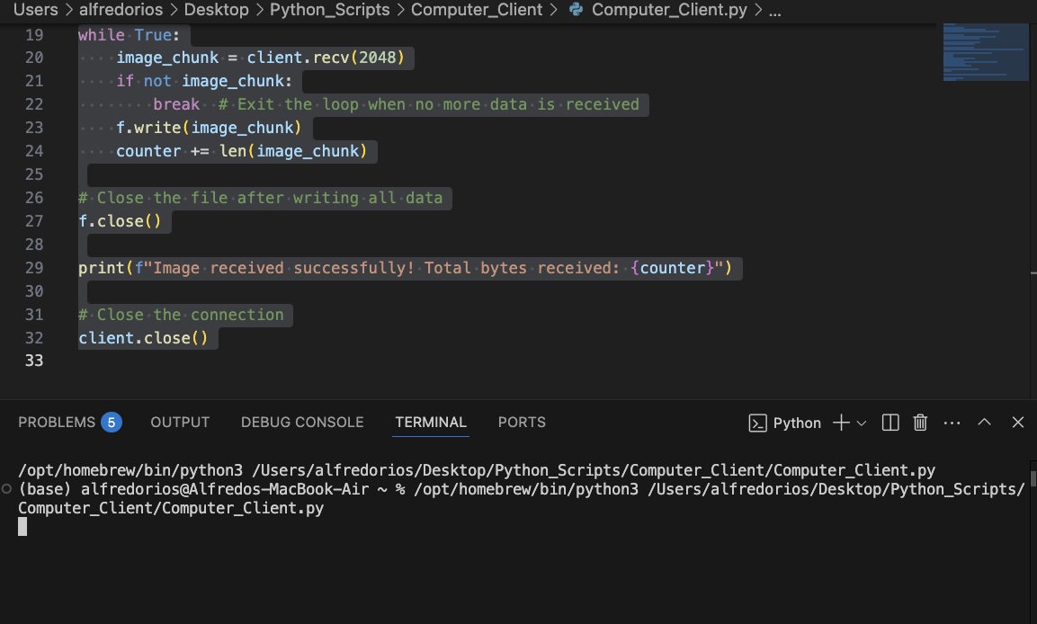
So now there is communication between the computer and the Xiao server but the picture I received does not come complete. So there I need to work more on this.
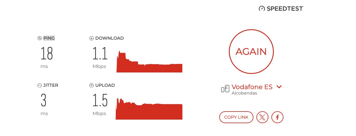
Also I wonder if some of the glitches I have experienced is due to the speed for the 2.4 Gh network. Whenever I have measured speed is highly inconsistent with sometimes very low upload and download speeds like the ones below.
Putting all together
For the future it will need turn a lot of the code above in functions to be called in some macro scripts as to keep things clear. In general terms the functioning is the following:
Camera Trap
- Collect temperature data
- Take Picture (if time==time1)
- Send collected temperature data (if time==time1+20s)
- Send temperature data picture (if time==time2)
- Erase data picture and temperature data [loop]
Server Xiao
- Listen for data (if time==time1)
- Receive data
- Save Data to SD
- Send Data
- Erase data [loop]
Computer Client
- Message request
- Receive data
- Save data
- Display data
Final thoughts
- This week was challenging as communication between several components was hard to achieve. This requires detail attention in order to make sure that all components are in the same subnet.
- Internet speed might be the cultprit of failed connections try to monitor for this and only test under good conditions if possible.
- This week also Neil mentioned that there were some issues in wireless communication in the ESP32 system.
- The os module was quite useful to create, delete and move files I will be using often.
- Oleds can be super useful for debugging.
Here you can find a link link to the final project development page for this week.
Files
Have you?
- Linked to the group assignment page
- Documented your project and what you have learned from implementing networking and/or communication protocols.
- Explained the programming process(es) you used.
- Ensured and documented that your addressing for boards works
- Outlined problems and how you fixed them.
- Included design files (or linked to where they are located if you are using a board you have designed and fabricated earlier) and original source code.
- Included a ‘hero shot’ of your network and/or communications setup