1. Group Assingment
- group assignment:
- measure the power consumption of an output device
- individual assignment:
- add an output device to a micro controller board you’ve designed, and program it to do something
The full group assignment can be found here
For this week’s assignment, we measured a LED and a DC motor. We used a power supply station where the voltage can be set to a specific value and the amperage can be limited to a maximum. This power supply displays the current being used as well as the total power consumption in watts.
Before proceeding, we define power as:
\(P=IxV\)
where I is current (in amperes) and V is voltage (in volts). Power is typically measured in watts and can be estimated as a function of time, e.g., watt-hours.
Led measurement
We set out to measure a blue LED. Initially, we did not get any readings. Most power supplies have a minimum current threshold below which they might not detect or display any current, which could explain this issue.
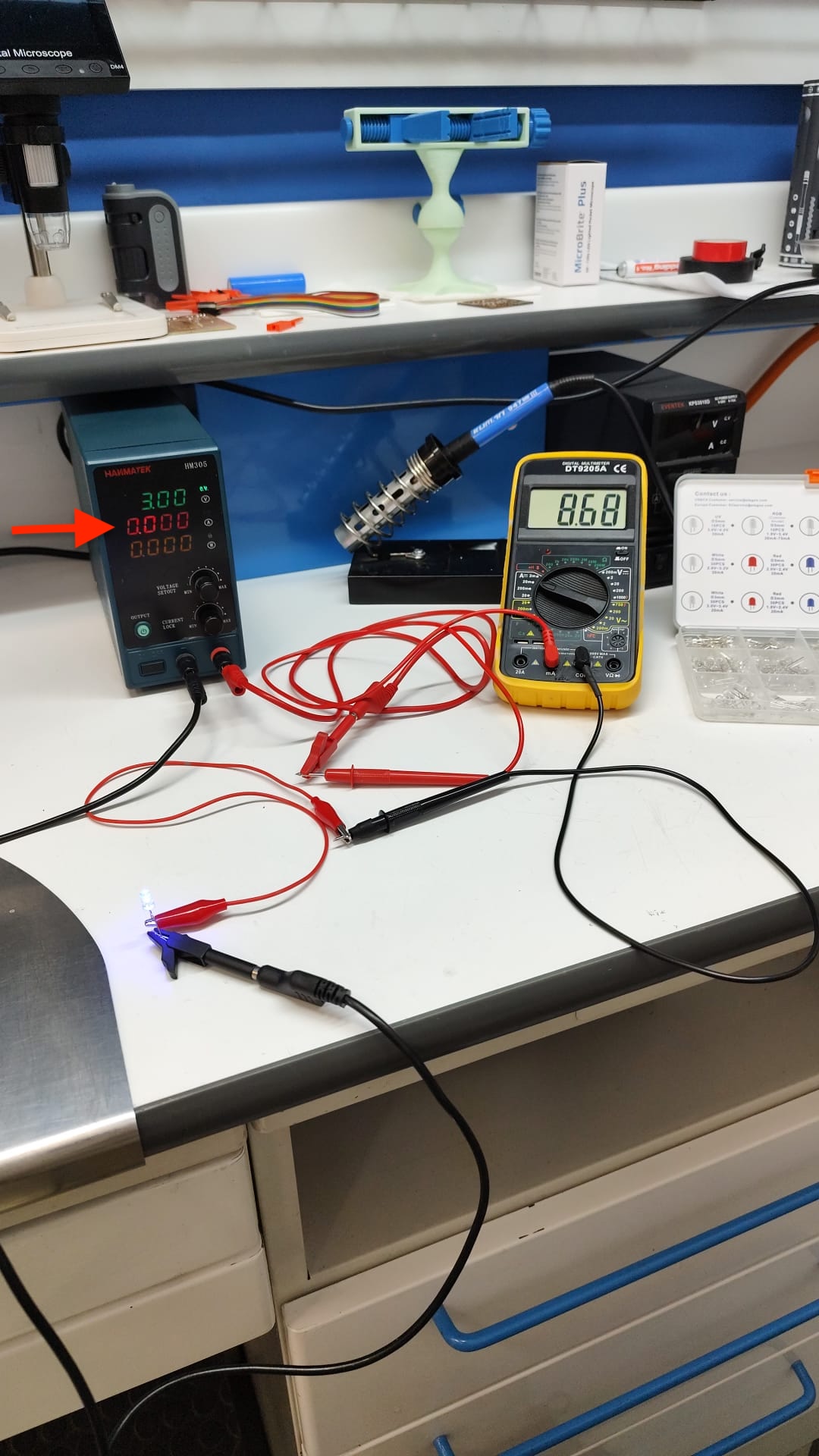
We had to incrementally increase the maximum amperage setting on the power supply until we obtained a reading. Afterward, we compared this reading with that of a multimeter and noticed a significant discrepancy (4 mA vs. 8.48 mA).
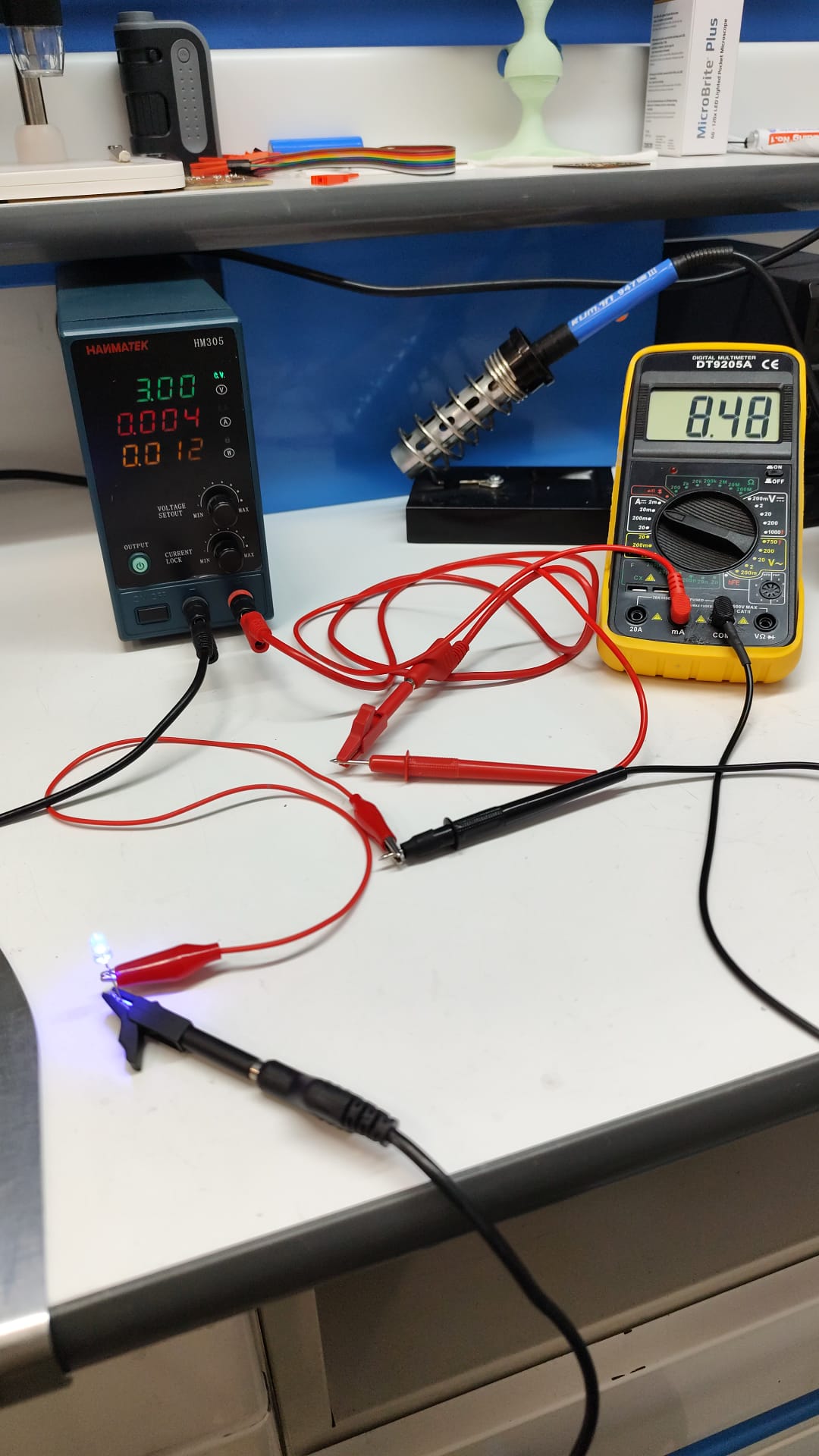
This discrepancy highlights the importance of considering the specifications of measurement tools. For example the Hanmatek power supply has a readback resolution of 10mV.
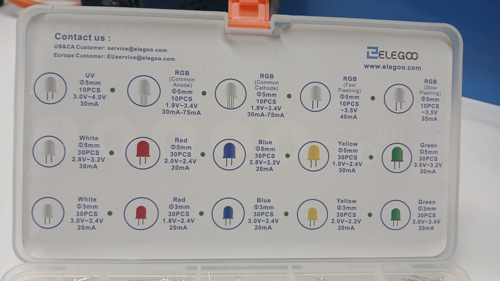
From the chart above, we observe that the current drawn by different LEDs varies between 20-40 mA. This suggests either that the multimeter might also lack sensitivity measure accurately voltage at low values.
DC Motor
The motor used was a DC motor with built-in gears. Its specifications are:
- 12VDC
- Current@ Max Efficiency (RPM): 120
- Current @ Max. Efficiency (mA) 74
- Price: 10.95 US$
We set the power supply to 9V, and the motor drew 74 mA while consuming 0.66 watts.
Under these settings, the motor could operate at best for approximately 7.43 hours using a 9V alkaline battery (550 mAh / 74 mA) and 16.21 hours with a lithium battery.
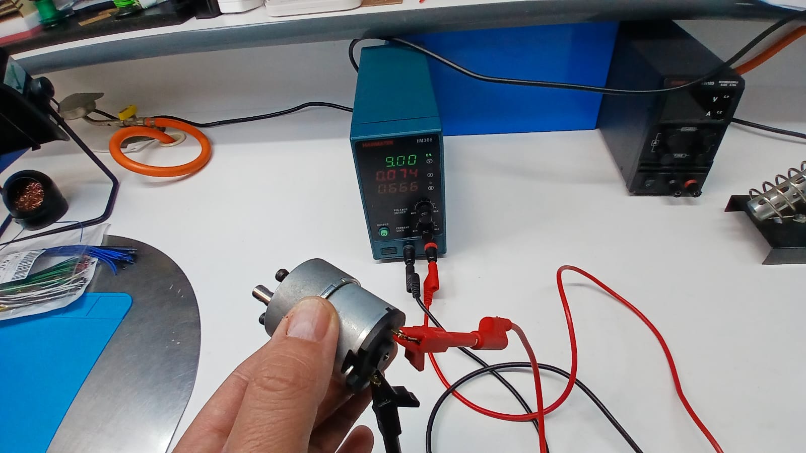
When reducing the voltage to 5V, the motor drew 54 mA and consumed 0.26 watts. We also observed that applying pressure to the motor shaft increased power consumption, reaching 0.45 watts.
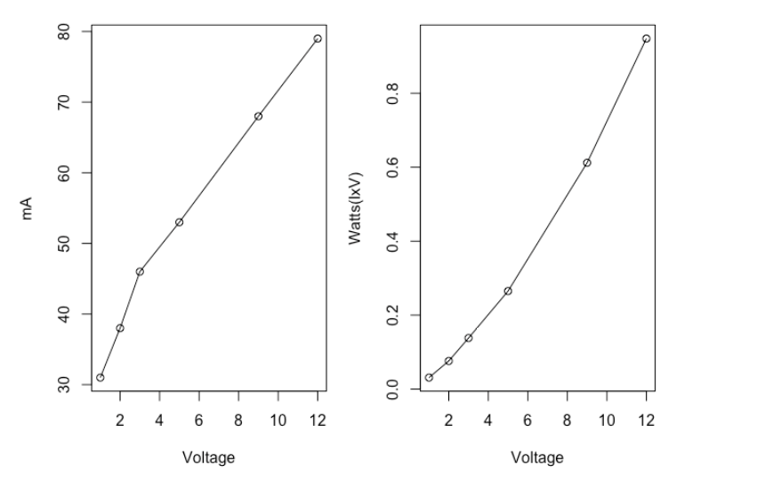
We continued measuring power consumption and plotted Current (I) vs. Voltage (V) and Power (W) vs. Voltage (V). Below 1V, the motor stopped moving.
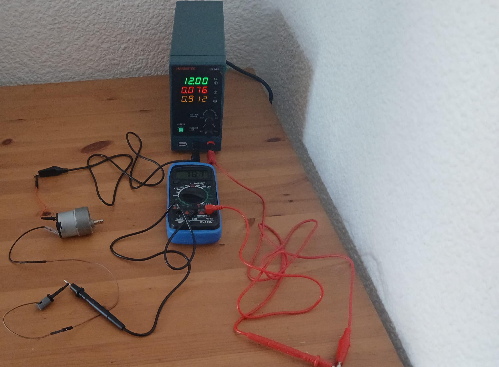
Finally, we compared the current values measured by the multimeter and the power supply. For the motor, both readings were very similar. The multimeter was set to mA mode for this comparison.
Final Thought: It is essential to consider power consumption, as it determines how long a device can remain operational. Even small component changes can significantly impact energy efficiency and battery life. This principle applies to simple components like LEDs and more complex ones like H-bridges, where MOSFETs can replace transistors to enhance efficiency.
2. Individual Assigment
I wanted to use the individual assignment to develop a part of my final project. My final project includes a DC motor with gears, the same one that presented in the group assignment. The motor will be used to roll up a tape covered with glue. The motor will use a battery 9V cell as an energy supply.
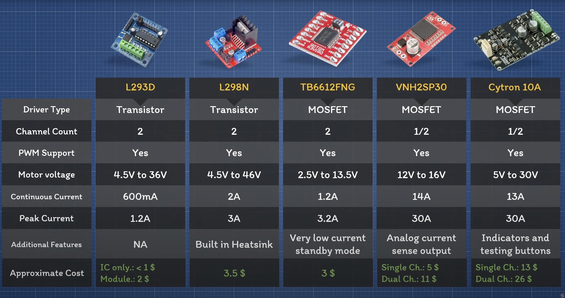
In order to control this motor I decided to use the TB6612FNG H bridge. The advantages of this bridge is that it can use a voltage range from 2.5 to 13.5V. This mosfet bridge consumes little energy and has and has a low power saving mode.
https://www.youtube.com/watch?v=PVyAcgYkzDs
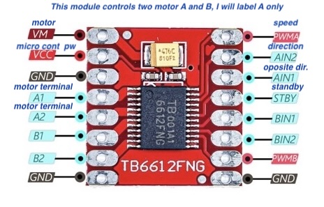
Below, you can see the labeling of the component pins and their functions. Note that this H bridge has the ability to control 2 motors that is why there are labels A and B. My project only needs to control one motor.
Pins:
- AI1 and AI2: Are connected to digital pins on the board and will control the direction of the motor.
- PWMA: will control the speed of the motor, it needs to be connected to a PWM able pin in the MCU board.
- VCC will deliver voltage from the MCU Board to the H bridge.
- A01 and A02 will source energy to the motor.
- VM and Ground(on the left) are connected to an energy source.
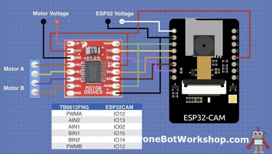
Previously, I looked for projects online that use this bridge and as well an ESP32 card, I found this project from the dronebotworkshop to operate a small car.
I followed their schematic for the H bridge as well as for the inclusion of a LM2596 voltage reduction component. The latter is of particular importance if we want to use a the battery to source the power to the micro controller unit.
To mount all of these electronics I designed a board in Kicad, I wanted to divide the board in two sides, one destined to the motor connections and the other one destined to the micro controller unit.
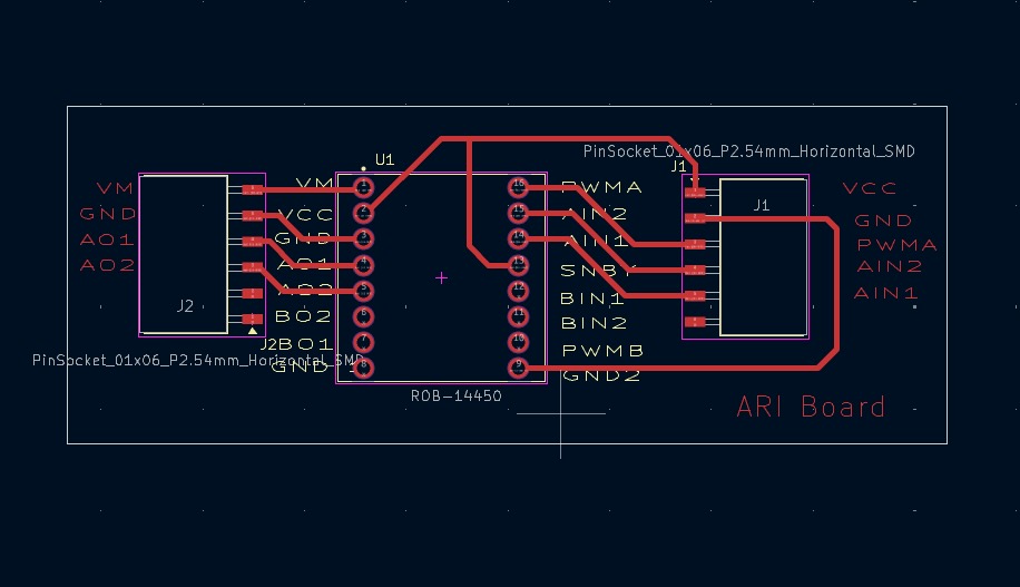
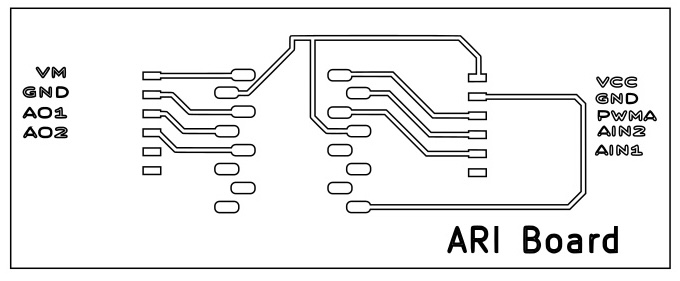
One of the initial issues given the small size of the H bridge was that the space is quite limited. I addition, we only had is zigzag pins in the lab. The advantage of using these pins is that they will also help space the pins making it easier to solder them. For this reason, I modified the footprint of the H bridge pads to follow the pin header spacing in the footprint editor. I also wanted to label the pin sockets in order to avoid confusion. The resulting modified Kicad file was:
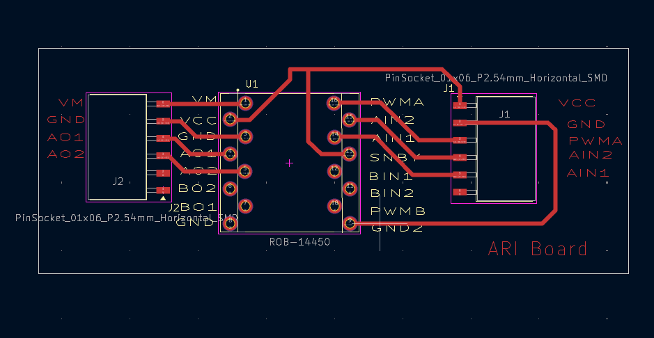
Then I cut the board,
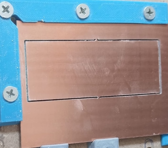
And then I engraved it.
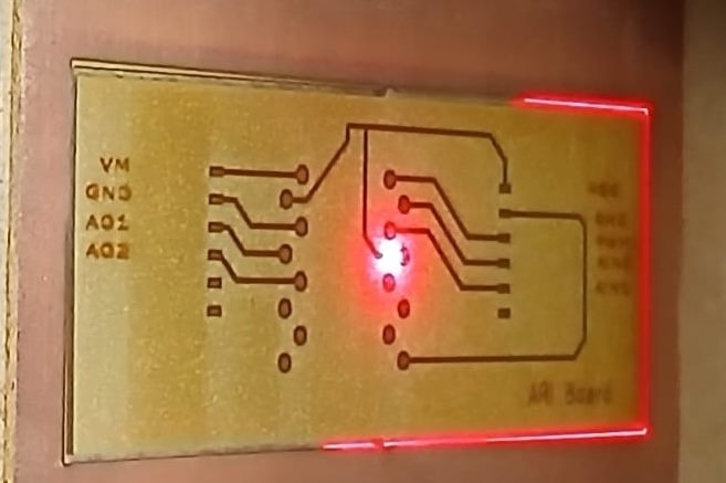
Given that the pads were so small the pins for holding the board were really hard to solder. Eventually, I lost one of the pads and I decided to cut and engrave a second board. This time I modified the pads in Inskape.
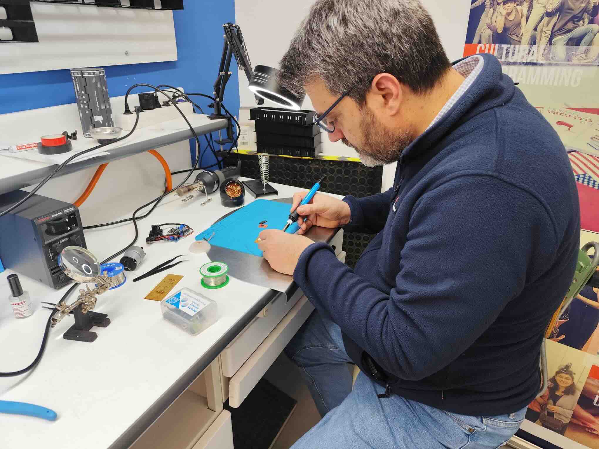
After producing the board I soldered the electronic components.
After soldering, I decided to test the two boards i.e. the MCU testing board I previously designed before and the h bridge board. For this I asked ChatGPT to generate some code to move the motor, which you can find below. I used the following prompt: Please get me a micro python code to control a h-bridge TB6612FNG H-Bridge controller I only need to use one motor … make this code for Ziao ESP32 S3 using gpio one to four
Below you can find the generated code.
from machine import Pin, PWM
import time

# Define motor control pins
PWMA = PWM(Pin(1))  # PWM pin for motor speed
AIN1 = Pin(2, Pin.OUT)  # Direction control
AIN2 = Pin(3, Pin.OUT)  # Direction control
STBY = Pin(4, Pin.OUT)  # Standby pin

# Set PWM frequency and duty resolution
PWMA.freq(1000)  # 1 kHz PWM

def motor_forward(speed):
    """Move motor forward at given speed (0-1023)."""
    STBY.value(1)  # Enable motor driver
    AIN1.value(1)
    AIN2.value(0)
    PWMA.duty(int(speed))  # ESP32 uses duty 0-1023

def motor_backward(speed):
    """Move motor backward at given speed (0-1023)."""
    STBY.value(1)  # Enable motor driver
    AIN1.value(0)
    AIN2.value(1)
    PWMA.duty(int(speed))  # ESP32 uses duty 0-1023

def motor_stop():
    """Stop the motor."""
    STBY.value(0)  # Disable motor driver
    AIN1.value(0)
    AIN2.value(0)
    PWMA.duty(0)

# Example usage
motor_forward(512)  # Move forward at 50% speed
time.sleep(6)
motor_backward(1023)  # Move backward at full speed
time.sleep(4)
motor_stop()
Here is a description of what the code is doing: is setting out the pin AIN1 or AIN2 to one indicate to the bridge the direction of the motor. Then it sets the value from 0-1023 to set the pulse width to control the speed. Higher the value higher the speed. And then, it packages different combinations of these values as functions to keep things organized and easy to reuse them. Last the the code tests the functions for the motor to go forward for 6 seconds at 50% of the speed and then switch the direction backward and increases the speed to 100% and then it stop.
Once the code was sent in, there was no response from the motor [crickets sounds]
After doing some debugging with the multi-meter I realized that there were some issues with the soldering of my board. After re-soldering these connections, the motor would go forward, and stop but it would not go backward. I started to test the conductance between the two boards, tracks pins etc but could bot find the culprit.
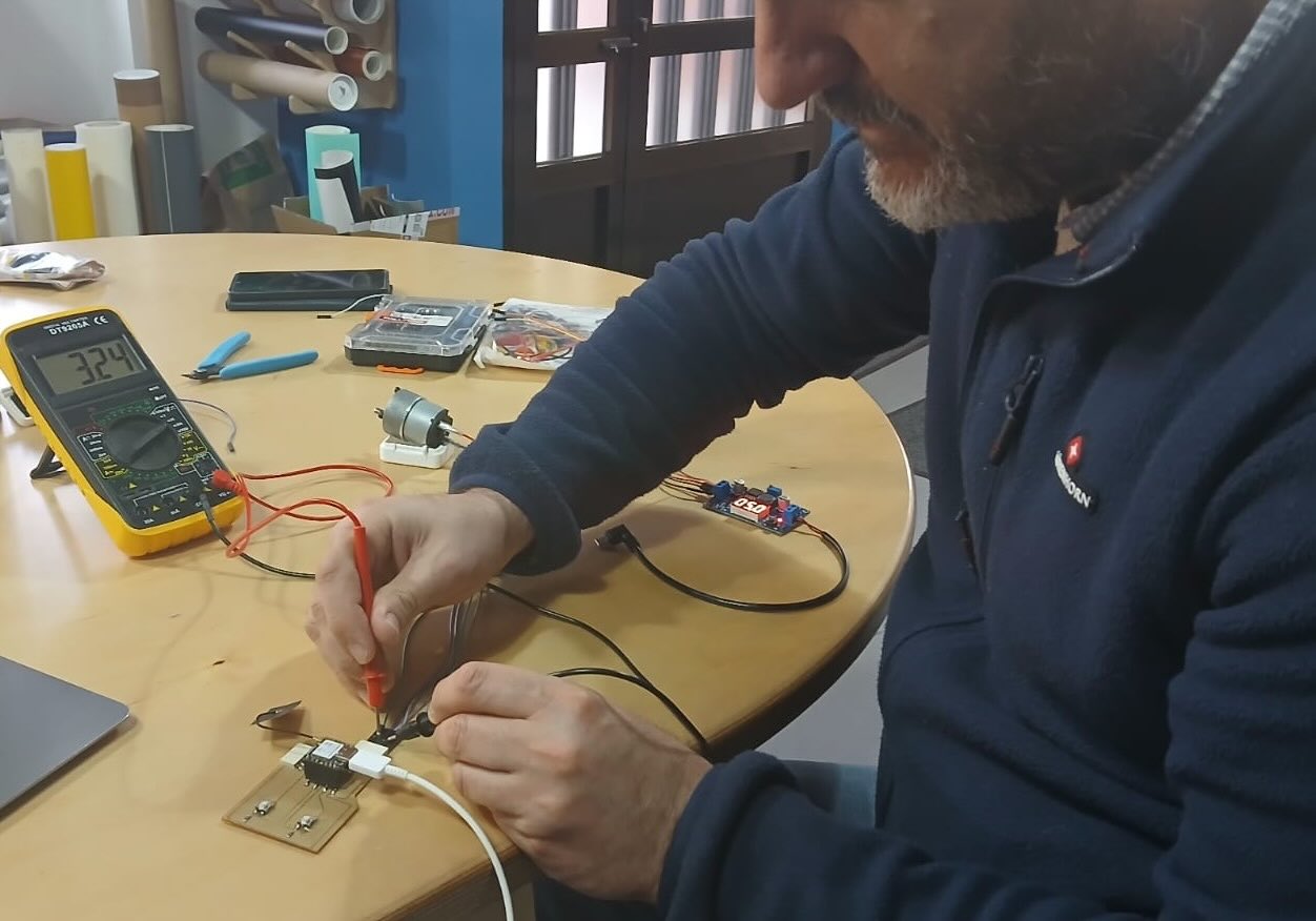
After talking to Mickael he pointed out that it could be my soldering of the MCU pins. I had been over conservative in the amount of solder I delivered to the board pin pads. Below you can see a picture of the issues I describe.
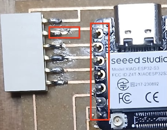
Once I re-soldered the MCU board pins the board would do what it was supposed to, that is the motor would move forward stop and move backwards.
Next, I wanted to test if I could use a nine Volt battery to drive the motor and provide energy to the MCU board. So I connected an USB C cable to the output of the voltage reduction module which would reduce the voltage from a 9V battery cell and reduce it to 5 volts to power the MCU. I also recorded the script and rename it to main.py which will launch the script once a board is no longer connected to a computer. This worked well.
Testing the motor with the sticky tape
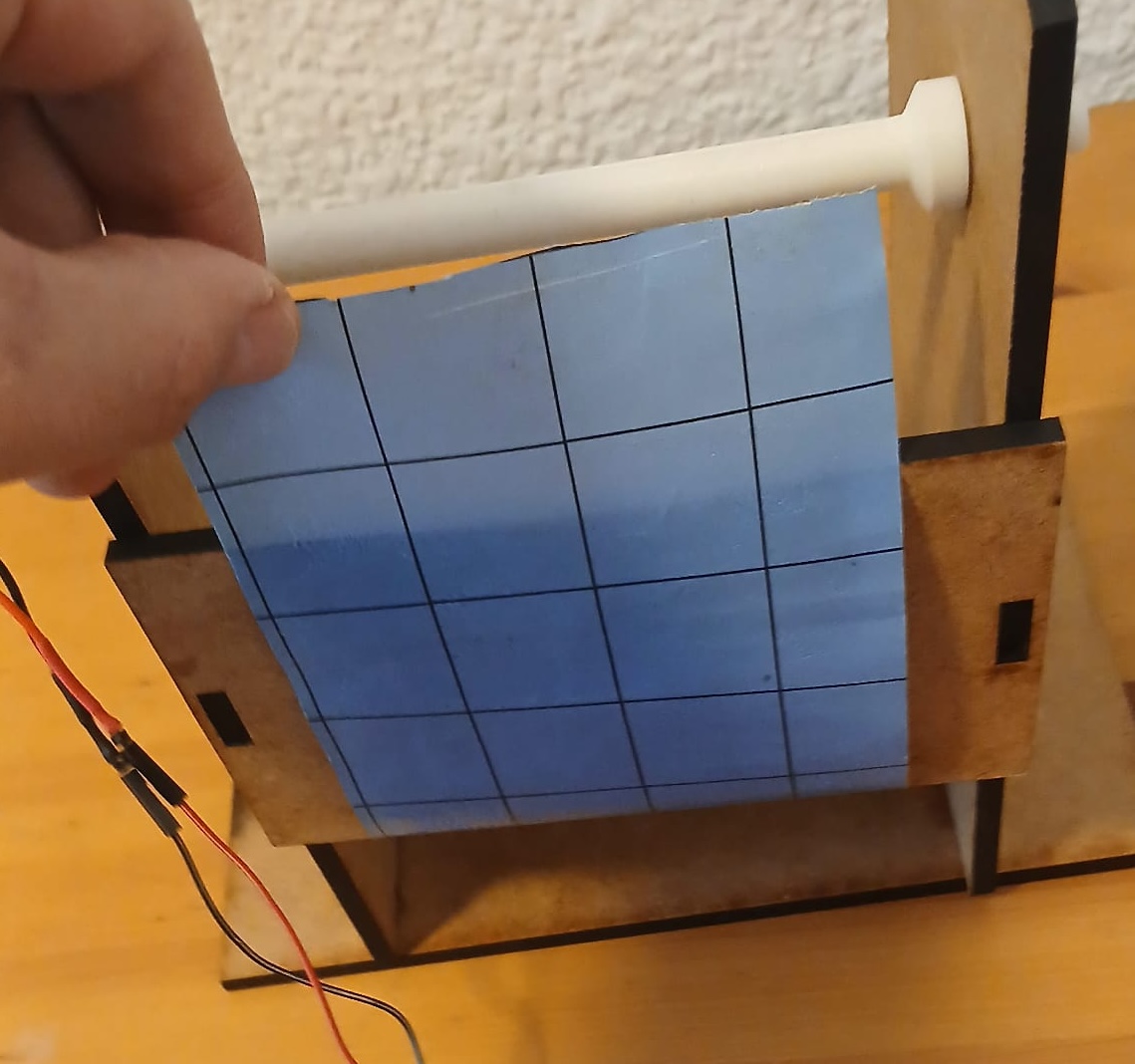
I wanted to test if the motor I am using could roll up a sticky tape. For this I mounted in the previous mdf house I designed. And designed a PLA connection to the motor with a slit where you could insert the tape.
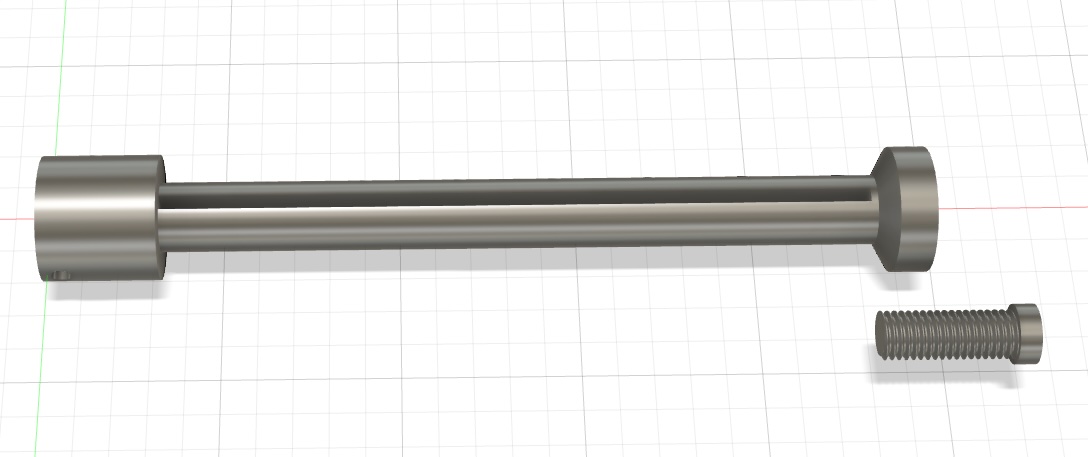
For this I designed and printed a piece of PLA plastic to connect the motor to the roll of tape, which I will define as the motor-tape connector. Below you can find a picture of a the fusion design. For this design I used the tool “Thread” in the create menu. First, the thread I place would not print until, I realize that I had to press modeled.
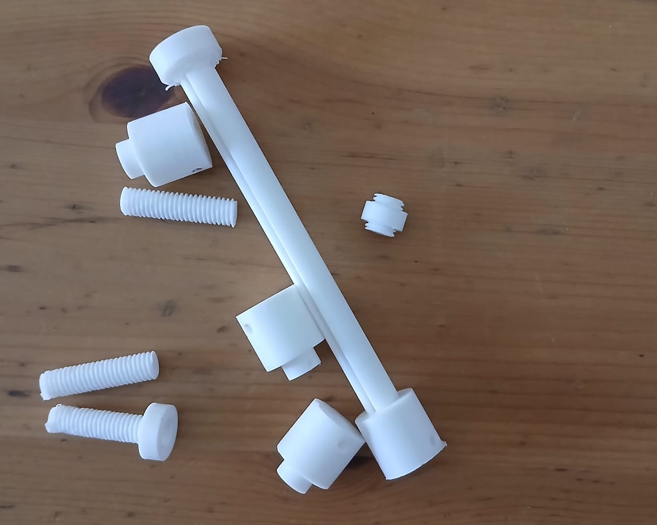
Here is some waste material.
1. Using the test board to control the motor
Then, I wanted to use the board as intended which was to used the buttons to control for this. I modified my old button program and included the functions motor_forward and motor_stop in the while loop. I also commented out the lines that told the micro controller to wait.
buttonA = Pin(8, Pin.IN)
buttonB = Pin(9, Pin.IN)

while True:
    if buttonA.value():
        print("A pressed")
        motor_forward(512)
        #time.sleep(0.5)
    if buttonB.value():
        print("B pressed")
        motor_stop()
        #time.sleep(0.5)
Power Consumption of the System
Then, I included the tape and sourced the system in its entirety with a power supply (no USB connections to the computer) so I could get some measurement of power consumption when supplying 9V.
You can see that the power comsumption ranges from 0.6 Watts when iddle to 2.2 Watts when the PWM is set up at 1000.
Testing an OLED
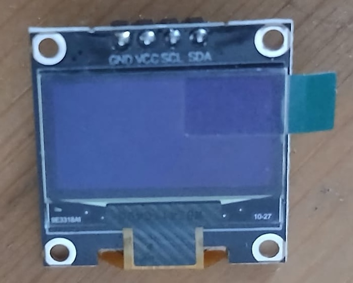
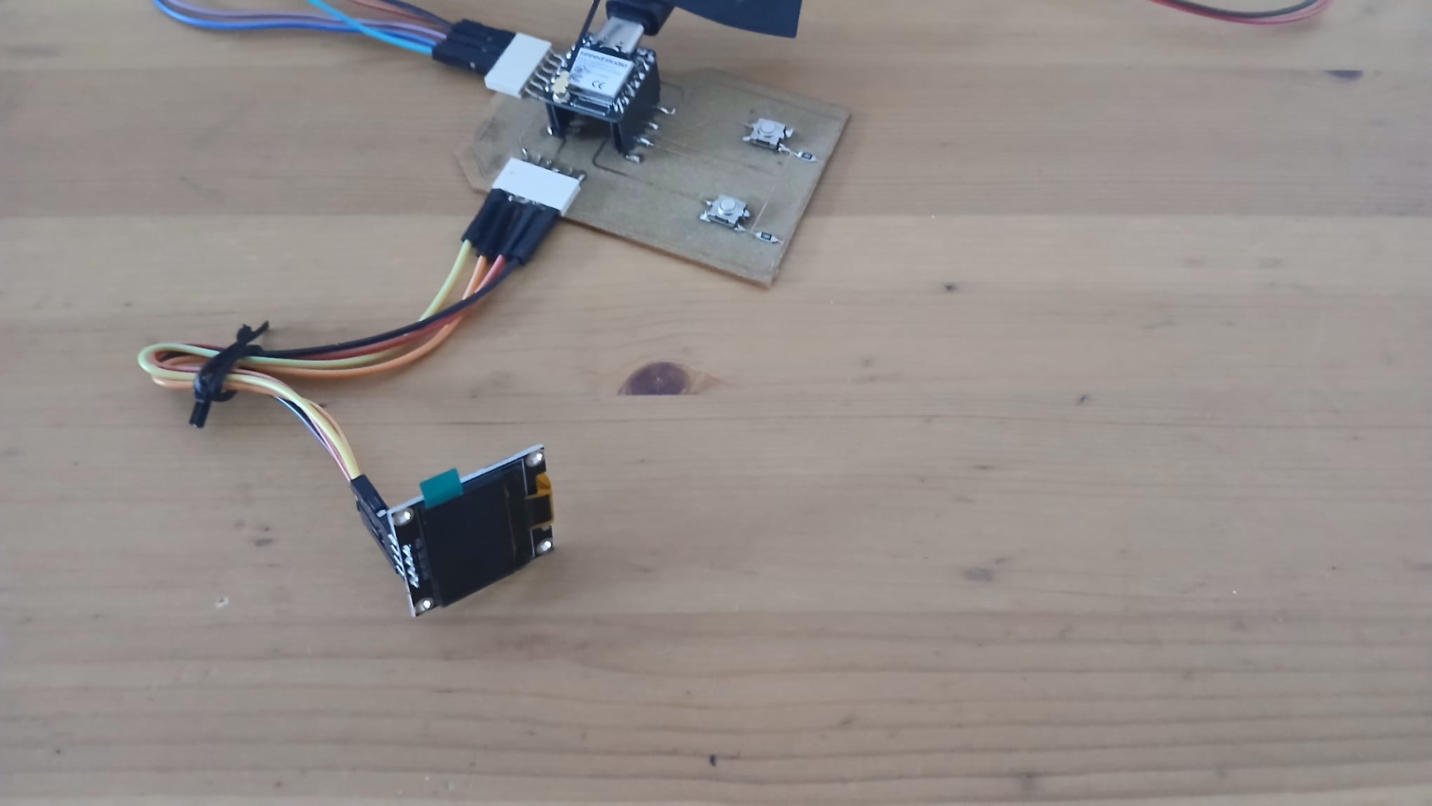
I used a second output an OLED display. This output device uses the SDA (GPIO 5) and SCL (GPIO 6) pins of the Xiao ESP32S3. I connected a OLED display to show the PWM value when the forward button was pressed and the word “STOP” when the stop button was pressed. For this I used a library ssd1306 and modified the motor python functions. In the next section you can see a video of this.
here is a bit of the code used
import ssd1306

# OLED
i2c = I2C(sda=Pin(5), scl=Pin(6)) # indicates the GPIO pins
display = ssd1306.SSD1306_I2C(128, 64, i2c) # arguments are the size of the display and the connection specified above

## Then modofied the function

def motor_forward(speed):
    """Move motor forward at given speed (0-1023)."""
    STBY.value(1)  # Enable motor driver
    AIN1.value(1)
    AIN2.value(0)
    PWMA.duty(int(speed))  # ESP32 uses duty 0-1023

    display.text(str(speed), 0, 0, 1) # Here converts the PWM value to a string and sets the position for it to be displayed
    display.show() # Displays the text
    display.fill(0) # Turns off all the pixels.
What’s next…
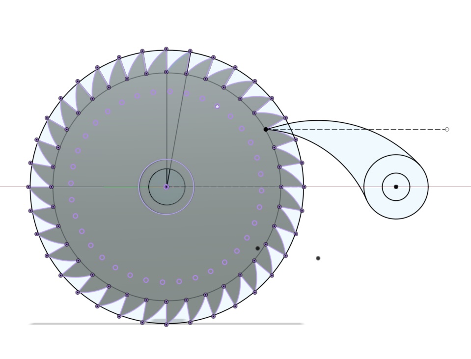
There is a lot of ways to reduce friction of the tape which increase power consumption. There was also a lot of snaping of the tape. So, my guess is that is because the tape roles back? I started design a ratchet and pawl so the role would not go back after this tutorial.
 ###
Learnings
- It is a good idea to check all soldered components prior to testing including pads
- Do not be so conservative when soldering.
- Power consumption will vary drastically with pulse modulation.
- It learn how to set my voltmeter in series in order to measure current.
- The power supply might not be very accurate for low amperage.
Below you can find a link to the final project development page for this week: link
Have you?
- Linked to the group assignment page.\(\checkmark\)
- Documented how you determined power consumption of an output device with your group.\(\checkmark\)
- Documented what you learned from interfacing output device(s) to microcontroller and controlling the device(s).\(\checkmark\)
- Linked to the board you made in a previous assignment or documented your design and fabrication process if you made a new board.\(\checkmark\)
- Explained the programming process/es you used.\(\checkmark\)
- Explained any problems you encountered and how you fixed them.\(\checkmark\)
- Included original source code and any new design files.\(\checkmark\)
- Included a ‘hero shot’ of your board \(\checkmark\)
