Final Project
This week I worked on defining my final project idea and started to getting used to the documentation process.
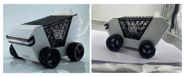
Mini Continattor
Mini Continattor
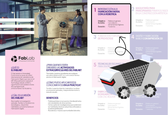
It is an educational robot in which the students of the Introduction to Digital Fabrication workshop can learn to use the machines of the laboratory following a fab academy approach, but because this course is aimed at all students of the continental university is that a pre-designed project must be used. These workshops are offered even to non-engineering careers because they are extracurricular activities such as soccer, basketball, etc. Our robotics courses, 3d printing, 3d scanning are courses that start from the basics to the complex, for that reason and for the development time is that it works with a pre-designed project.

COMING SOON 2025
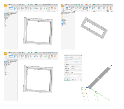
Design
- First we made the most important sketch that integrates most of the parts of minicontinattor, with this sketch we will make the extrusions to obtain most of the parts.
9mm MDF structure
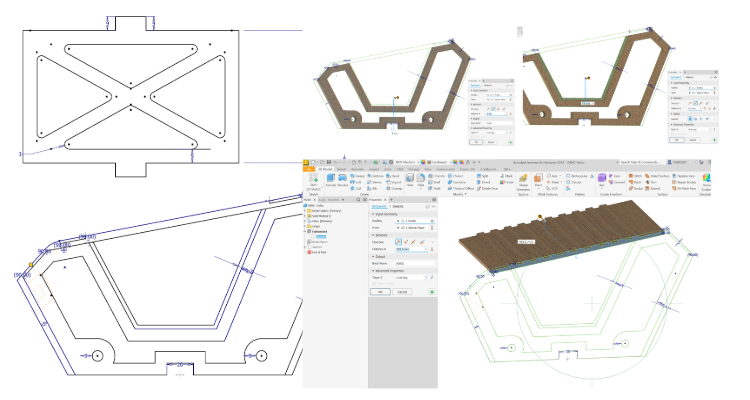
- 3D printing rounded edges of the lateal silhouette is obtained the desired dimensions, then it is extruded.
- Extrude to the distance of the lateral structure plus the thickness of the acrylic to be veneered.
- Add the rounded edges
- A sketch is made projecting some geometries.
- To make the corresponding extrusions
- This design flow is repeated in two more pieces
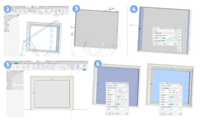
Acrylic veneer
- For the acrylics based on the measurements of the frames, the sketches are designed and extruded.
- This operation is repeated for the other veneers of the frames with rounded edges, which are 3 more pieces.
- Then for the lateral veneers with the silhouette of the side, a sketch is made to generate the mesh.
- And it is constructed at the distance of the chosen thickness.
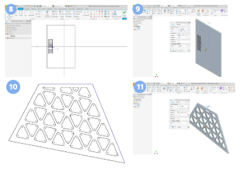
- The same for the transparent acrylic without the mesh.
- This procedure of geometry projection and use of the sketch with the main silhouette to perform extrusion operations is repeated for the other ‘pieces of the veneer.
- Finally we generate some files to organize the 2D lines that will be used in the laser cutting and CNC machining.
- And we export it in DXF
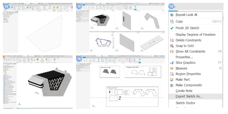
The same way for cnc machining
The parts to be machined are part of the final project Mini Continattor AGV corresponding to the structure of the robot, the materials to be used are two MDF sheets of the following dimensions. In the case of the length and width measures are minimum measures, so it can be bigger, however the thickness must be the same.
| Material | Thickness (mm) | Length (mm) | Width (mm) |
|---|---|---|---|
| MDF | 9 | 700 | 200 |
| MDF | 5.5 | 200 | 120 |
The tool we will use for this exercise is the following:
| Attribute | Details |
|---|---|
| Tool | 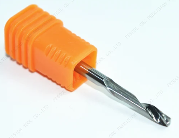 |
| Type | Flat End Mill |
| Diameter (Tool) | 3.175 mm |
| Diameter (Shank) | 3.175 mm |
| Tool Length | 38 mm |
| Shoulder Length | 17 mm |
| Approximate Cost | 9 USD |
- For the fabrication of the ‘3d printed parts, it must be exported in a stl format as seen in the example.
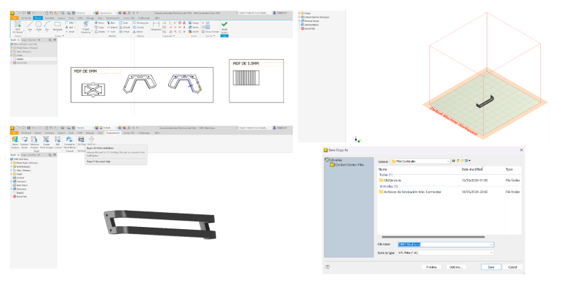
- In the parts list we have the following parts
- Then we import these files in the ultimaker cura slicer and we classify them according to the material which they will be manufactured in PLA we have the following parts
- And in TPU 95A we have the flexible parts which are the rollers of the wheels.

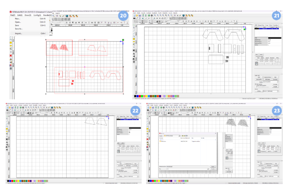
- To manufacture the laser cut parts, first we must import the dxf to the rd works software.
- And generate 3 files for 3 different colors and thicknesses of acrylics to use indicating the speed and corresponding powers.
- To save the file and transfer it to the machine we must click on “Save to U File” assign a name and save it in a USB removable drive.
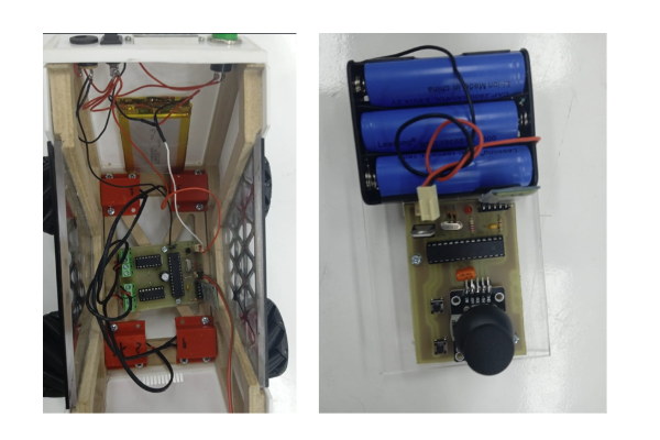
- At this moment MiniContinattor is working with a board designed with an ATMEGA and a remote control, but the board with a SEEED XIAO and and SMD components is under development.
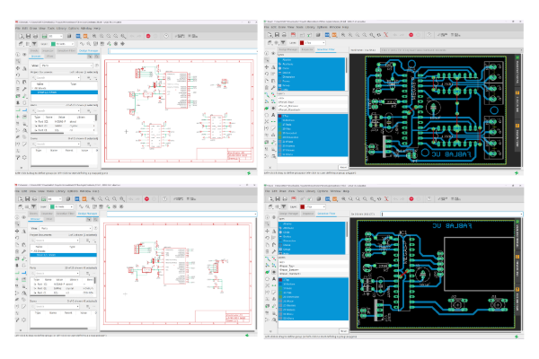

CNC electronic board manufacturing: Mini Continattor AGV Board
- Design - EasyEDA
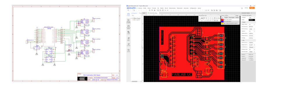
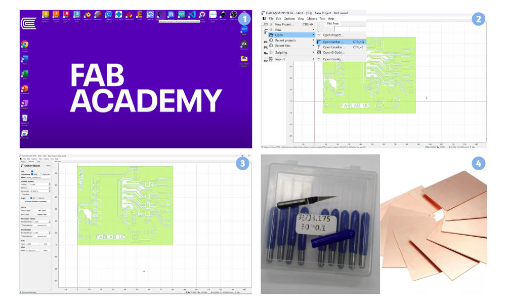
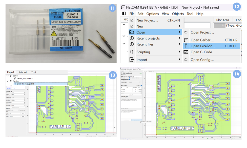
- Manufacturing: FlatCAM To configure the fabrication, double click on the FlatCAM v8.991 beta application.
- Top Layer Then we import the gerber file, being SMD we will use the “Top Layer” file.
- Then we align as much as possible with the first quadrant with the tool “Offset” in this case Vector: (-7.244,10.3)
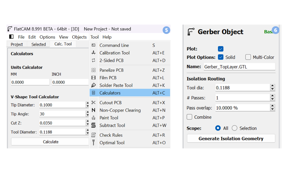
- We analyze the milling cutter to be used Shank Diameter 3.175 mm Tip Diameter: 0.1 mm Angle: 30deg And the thickness of the copper of the fiberglass board Cut Z: 0.035
- With this data we use the tool “Calculators” to find the tool diameter, which in this case gives us as a result 0.1188.
- We go back to the gerber file and copy this value obtained to finally use the “Generate Isolate Geometry” tool.
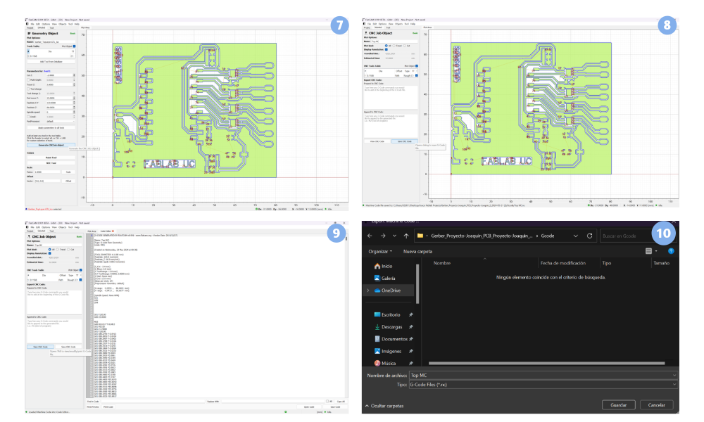
- As a result we get the outline of the tracks and click on “Generate CNC Job” to create the .NC file that will be used in the Mini CNC. We do not worry about the “Feed Rate” and “Spinde Speed” because we will control them manually with the DSP and the inverter respectively.
- This tab will appear and click on “Save CNC Job”.
- In the “View CNC” section we can see the generated code and modify it if necessary, but in this case it will not be necessary.
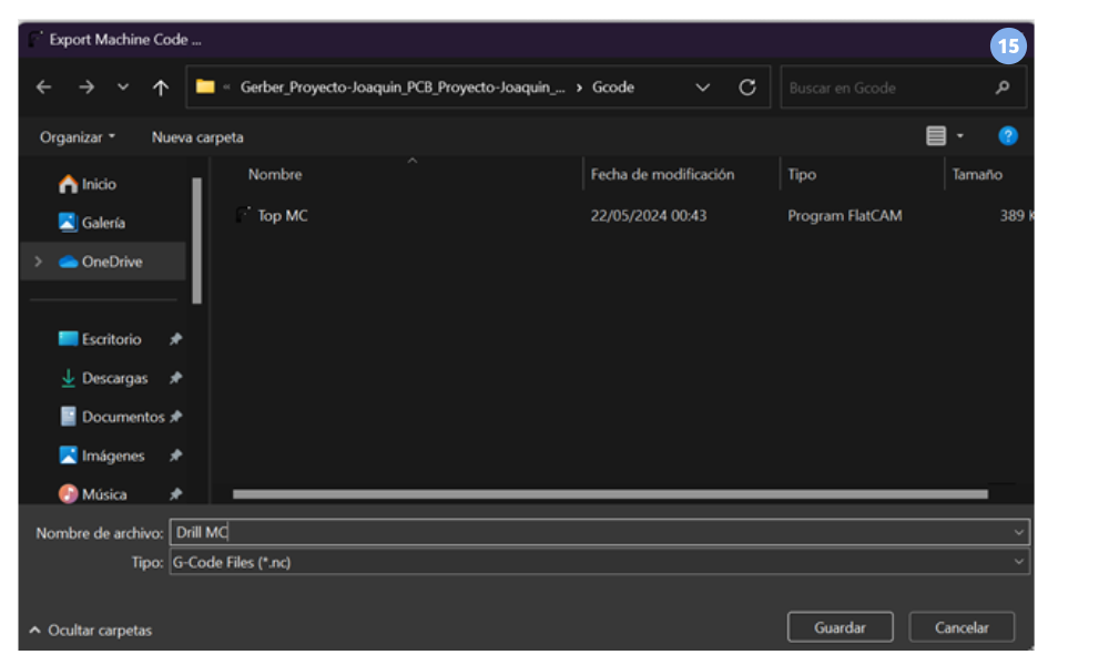
- Click on “Save CNC Code” to select the location of the file and assign a name and click on “Save”.
- Drills There are some components that are being used that need this type of files as is the case of the circuit power stage terminal blocks that are the most suitable for these applications and commercially in Peru are not found this type of SMD components. We analyze the drill to use and we see that it has a diameter of 1.4 millimeters.
- Then we click on the “Project” section and then we click on “File”, “Open”, “Open Excavation”, “Open Excavation” and “Open Excavation”. Open”, “Open”, “Open Excellon” and select the file with the “Drills”.
- The “Excellon Object” tab will open, in case it does not appear we can look for it in the “Project” section looking for the selected Excellon file and click on Drills. We do not worry about the “Feed Rate” and “Spinde Speed” because we will control them manually with the DSP and the drive respectively, but if we change the “Drill Tool diameter” by 1.4 and align the holes with the same parameter that we indicated with the tool “Offset” Vector: (-7.244,10.3) and click on “Create Drills Gcode”.
- Then this window will appear and we must click on “Save CNC Gcode”.
- Select the location of the file and assign a name and click “Save”.
-
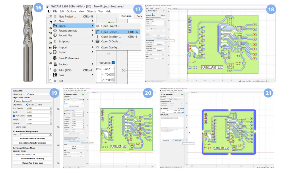
Cutout We analyze the cutter to be used and see that it has a diameter of 3 millimeters.
-
We open a new gerber to cut the edges of the board which is usually found as “Cutout” or “BoardOutlineLayer”.
-
As in previous operations we do not worry about the “Feed Rate” and “Spinde Speed” because we will control them manually with the DSP and the drive respectively, but we change the “Drill Tool diameter” to 3 and align the holes with the same parameter that we indicated with the tool “Offset” Vector: (-7.244,10.3) and click on “Cutout Tool”.
- Then we indicate the cutter diameter, the gap size, the margin and the number of gaps that prevent the part from moving during the machining process.
- Then click on “Generate CNCJob Object”.
- Click on “Save CNC Code”.
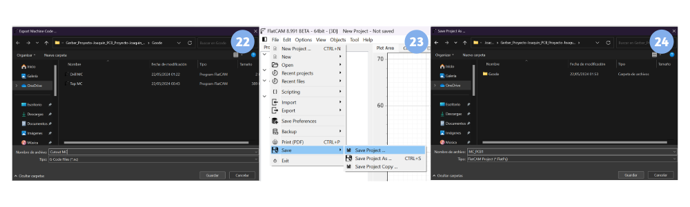
- Select the location of the file to transfer it to the machine.
- Save this file in case it is necessary to make a correction later.
- Select the location where the file will be saved and click on “save”. The 3 Gcode files will be transferred to the machine for manufacturing on a USB memory stick.
- The structure is complete as seen in the pictures.
- Open the Rhino 7 program by double clicking from the remote desktop. Create a new document by clicking on “File”, then “New” and a tab will open to select a template.
- Select the template, in this case we select the option “Large Objects - Millimeters” and click on open.
- Then we click on “File” then “Import”, then a tab will open in which we must select the file with extension .dxf where the geometry to be machined with the name “MC_MecanizadoCNC” will be found and we click on open.
- Set the default Import options and click on accept.
- Delete unneeded lines by clicking on the line and pressing the “Delete” or “supr” key.
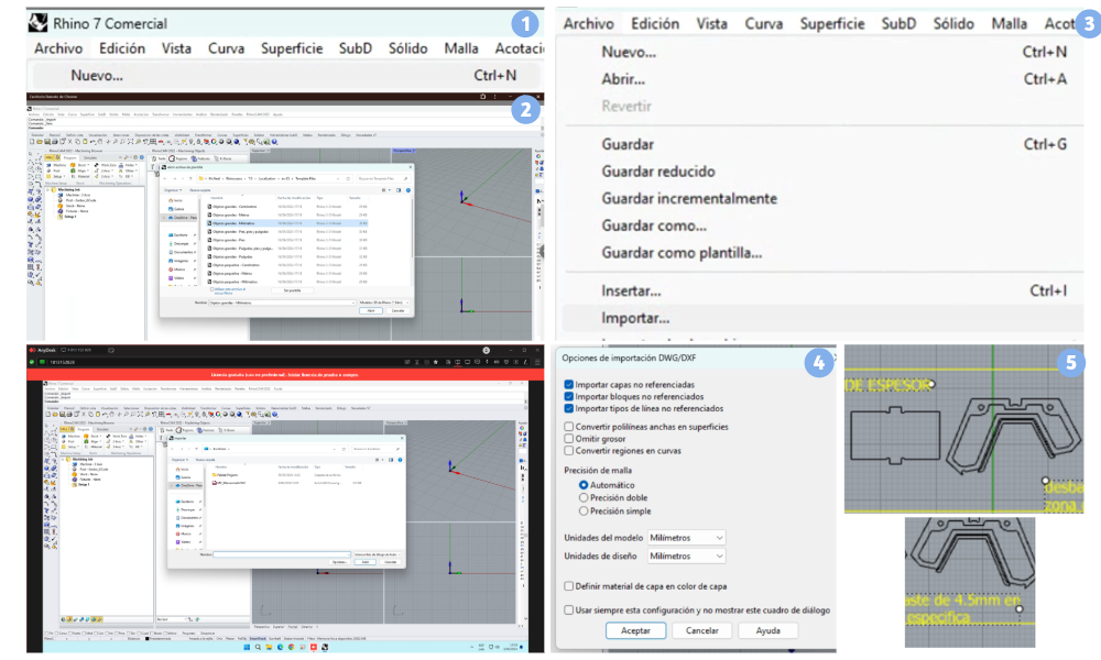
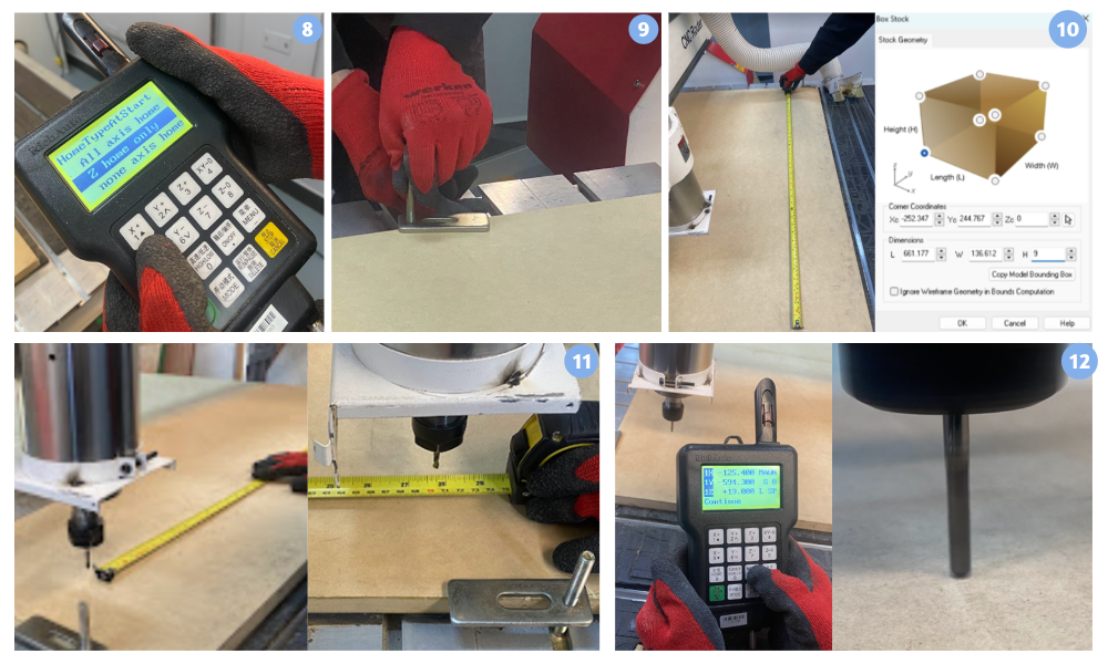
- Create the box stock, this will give us the minimum necessary dimensions of length and width of the plate to select a piece of the thickness of the design. Click on “Stock” and then “Box Stock”. Then click on “Copy Model Bounding Box”, indicate the thickness of the design, in this case 9mm in the “H” box and then select “OK”.
- Align the stock We look for the icon and click on “Align” and select “Align Stock”. A new tab will appear in which we must select in “Z Alignment” the option “Top” and in “XY Alignment” the option “South West” and finally click on “OK”.
- Align the “World Coordinate System” which refers to the coordinate system used as a reference for specifying the position and orientation of objects in a three-dimensional environment. In the context of CNC and manufacturing, the World Coordinate System is used to establish the initial position and orientation of the workpiece or blank relative to the CNC machine. This allows machining operations to be performed accurately and consistently throughout the manufacturing process.Then a new tab will appear in which we must select in “Set WCS Origin” the option “Set to Stock Box”, in “Zero Face” the option “Highgest Z”, in “Zero Position”, the option “South West” and finally click “OK”.
- The result of the alignment is as follows
- Then a tab will appear in which we can select the material from a library, in this case we will choose “Wood” and click on “OK”.
- Create the Work Zero The “Work Zero” refers to the origin point from which all cutting coordinates are measured. This point is essential because it defines the starting position of the machining process and serves as a reference for all subsequent operations on the workpiece. Then a new tab will appear in which we must select “Set Stock Box”, in “Zero Face” the option “Highgest Z”, in “Zero Position”, the option “South West” and finally click on “OK”.
- Create the operation 2 ½ Axis Pocketing We look for the following icon, first clicking on “2 axis” and then on “Pocketing”. A new tab will open with many sections, among them the first one we must modify is “Control Geometry” in which we must click on “Select Curve/Edge Regions”. The tab will close and to select the desired geometry.
- To select just click on the lines or curves and it will be marked in yellow color.
- To deselect just click on the yellow line or curve already selected while holding down the “Ctrl” key.
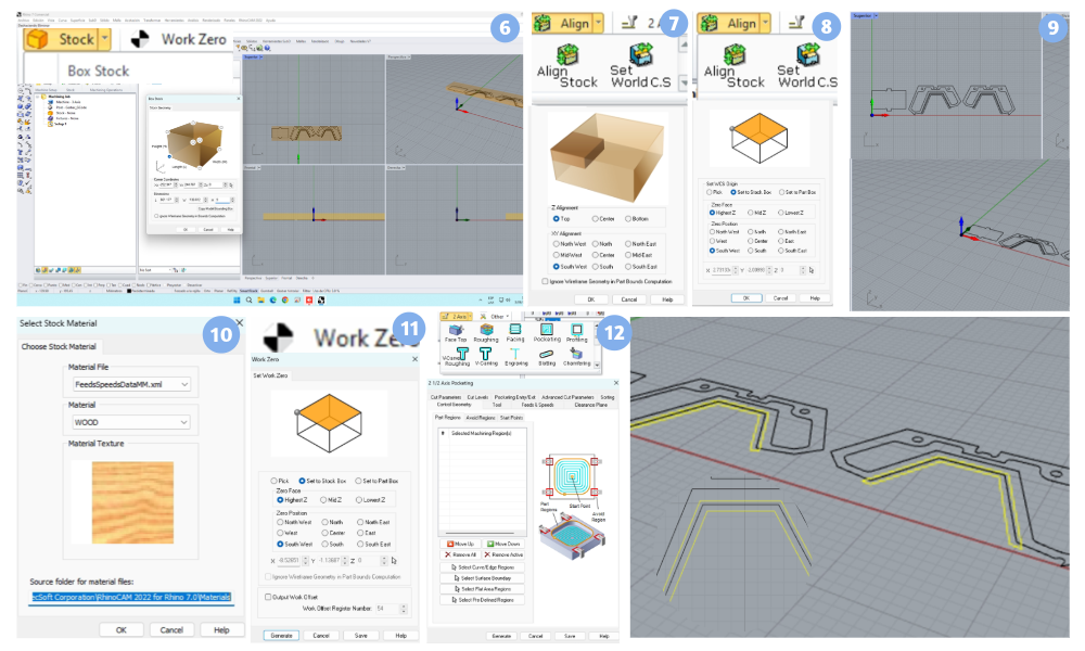
- When you have finished selecting the desired lines or curves, press the “Enter” key and the operation tab with selected machining regions will reappear.
- Then create the tool in the software in the “Tool” section by clicking on “Edit/Create/Select Tool …”.
- Then a new section will appear where we must indicate the characteristics of the milling cutter, these characteristics can be found in the section (1.7. Materials and inputs) or we can measure it again with the vernier to corroborate these measurements, then complete it, click on “Save as New Tool” and finally click on “Exit”.
- Then in the “Cut Levels” section we will indicate the height for the roughing that in this case for the design should be 4.5mm in “Total Cut Depth”. In Rough Depth/Cut for this case is 4.5mm, however not in all cases is equal to the total distance, the general rule is that the “Rough Depth/Cut” does not exceed twice the diameter of the milling cutter or drill.
- Create operation 2 ½ Axis Profiling - Inside We look for the following icon, first by clicking on “2 axis” and then on “Profiling”. For this operation the “Cut Geometry” section for the selection of the machining regions the process is the same as in the previous operation, but only in this case the lines or curves that require machining inside the lines will be selected.
- Then, in the “Tool” section we only have to select the tool already created previously, it is possible to create a new one, but since we will need the same one, we only select the one already created by clicking on “FlatMIll1” which is the name with which this tool was created.
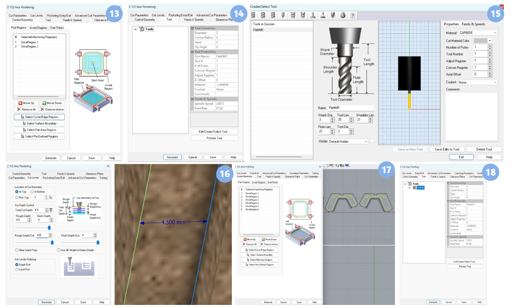
- The main difference is in the “Cut Parameters” section where we must check the box “Use Outside/Inside for Closed Curve” and then check the option “Inside”.
- In the Entry/Exit section we check the “None” option in “Entry Options” and “Exit Options”, since with a metal milling cutter (Aluminum) with a stock of MDF there is no risk that the tool will break or break so it is not necessary to apply a machining strategy.
- Create operation 2 ½ Axis Profiling - Outside We look for the following icon, first by clicking on “2 axis” and then on “Profiling”. For this operation the “Cut Geometry” section for the selection of the machining regions the process is the same as in the previous operation, but only in this case the lines or curves that require machining outside the perimeter of the lines and curves will be selected.
- The main difference is in the “Cut Parameters” section where we must check the box “Use Outside/Inside for Closed Curve” and then check the option “Outside”.
- The “Entry/Exit” section is the same as the previous operation.
- Renaming the operations for better organization By right clicking and clicking on “Rename” we can change the name of the operation to a more specific name in order to have a better organization and avoid possible future errors. By left-clicking on the folder icon and dragging it we can change the order of the operations.
- Simulation
We look for the “Setup 1” icon and right click on it and then left click on “Simulate”. Top view of the before and after machining
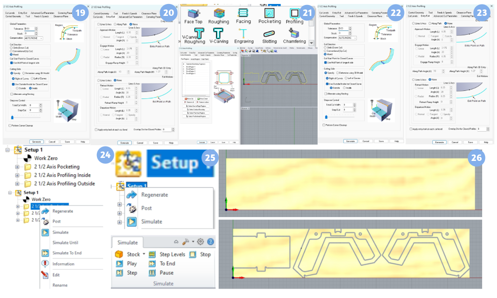
- Gcode Export Look for the “Setup 1” icon and right click on it and then left click on “Post”. Detail of the part with the 3 operations The tab will open where we select the location of the file, preferably a USB removable drive to transfer the file to the CNC Router machine and click on “Post”.
- When the file is saved, a notepad will open with the Gcode extension .nc.
- Save Rhino Files Click on “File”, then click on “Save as…”.
- Then the “Save” tab will open where we will choose the location where the file will be saved.
- The files are ready.
......
- Select the material to be used and its thickness in this case it will be MDF.
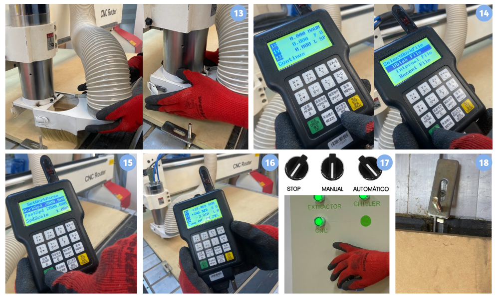
- Place and secure the Box Stock in four corners of the board to be used. Release the emergency buttons on the control board and the machine by rotating the buttons clockwise.
- Initiate the Start-up Sequence in Automatic Mode.
- Loosen the lock nut and remove the collet chuck with the tool.
- Place the tool to be used in the collet chuck and verify that the “Tool Length” or tool length matches the tool length indicated in the CAM software.
- Adjust the lock nut.
- Place the USB Flash Drive in the DSP.
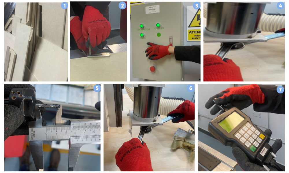
- Select the “none axis home” option, using the “1” and “5” buttons to move up and down respectively in the selection, finally press the green “OK” button to continue.
- Secure the MDF board
- Mark the origin point manually, measuring with a flexometer the maximum length and width of the indicated box stock,
- Calibrate the origin with the DSP in X and Y.
- Calibrate the origin with the DSP in Z.
- Insert and secure the chip extractor brush.
- Select the .nc file
- Select the feed rates
- Run the file and supervise the machining process.
- If an emergency occurs Turn off the machine by placing the control board knob in the STOP position and pressing the safety buttons.
- Upon completion of cutting on the machine Remove the fasteners.