2. Computer Aided design
In this assignment I will present the Model (raster, vector, 2D, 3D, render, animate, simulate, …) a possible final project, compress your images and videos, and post it on your class page.
Assigmnent checklist
| Item | Activity | Status |
|---|---|---|
| 1 | Modelled experimental objects/part of a possible project in 2D and 3D software | Done |
| 2 | Shown how you did it with words/images/screenshots | Done |
| 3 | Included your original design files | Done |
1. 2D Model
The inspiration for the design was the assignment I had to submit for the Integral Calculus course as a student at the Continental University, in which I had to present some application of integrals in real life.
 Then I remembered reading in a MAKERBOT FOR EDUCATORS guide that ” 3D printing can be used in a multitude of methods to better reinforce core learning objectives in a variety of subjects.
areas: from clear STEM applications in engineering and physics, to blended interdisciplinary projects involving history, music, foreign languages and more.” With that my presentation would be a “Highlight.”
Then I remembered reading in a MAKERBOT FOR EDUCATORS guide that ” 3D printing can be used in a multitude of methods to better reinforce core learning objectives in a variety of subjects.
areas: from clear STEM applications in engineering and physics, to blended interdisciplinary projects involving history, music, foreign languages and more.” With that my presentation would be a “Highlight.”

This project of a correction pen was perfect for the course, a business idea and now the Computer Aided Design assignment.
3D modeling:
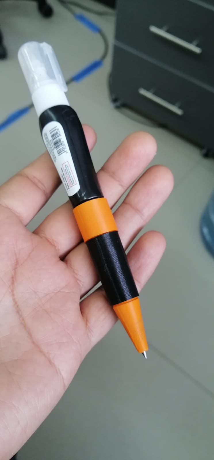
As a starting point, a Pilot G-1 100 pen was used to use its nozzle, charge and ink. These were reverse engineered to know their measurements. The bottom of a 4 ml Stanford corrector was also measured in order to integrate the parts in an ergonomic and light casing.
The housing was designed in Autodesk Inventor CAD software.
Calculation of the equations of a solid profile Outer profile
Calculation of the equations of the pencil casting profile

Calculation of the volume of a solid of revolution washer method Outer volume

Verification of volume calculation with Autodesk Inventor Software
The material to be used for the manufacture of the casings is Polymaker’s PolyLite PLA which, according to the manufacturer’s technical information, has a density ranging from 1.17- 1.24 (g/cm3 at 21.5C).

These materials when purchased wholesale have a lower price, so we will consider the maximum value of the density at 21.5 C, which is 1.24 (g/cm3) so that when replacing in the equation we get as a result the largest possible amount of mass, to avoid making a second retail purchase in the event that the material of the initial purchase is not enough. The units used in the equation are those of the International System, so the conversion of 1.24 grams per cubic centimeter [g/cm³], which is equivalent to 1,240 kilograms per cubic meter [kg/m³], is performed. The conversion from mm³ to m³ is also performed. These data are replaced in the equation and the mass per unit of the casings is obtained, but as we want to know what is the mass needed for 1500, we multiply the value per unit by 1500 and we obtain the total mass required. 0.04kg mass per unit 1500 units to be manufactured Mass per unit x units to be manufactured = Total Mass 0.04kg x 1500 = 60kg 1.4 Prototype fabrication The CAD design of the housing is sent to a slider where it is prepared for printing and exported in a Gcode format for the 3D printer to start manufacturing, the material chosen is PolyLite PLA silver SILK.

Results
Issues, musings, and learnings.
Pen selection: In order to be an ergonomic product, it was necessary to design a short housing, which reduces the ink capacity that the pen can hold and the durability of the product. This is solved by choosing the PIlot C-1 100 which has a larger load in cylinder area which compensates for the short height and equalizes the volume of ink the pen can hold. 3D Modeling: For modeling in Autodesk Inventor software, a mid to high-end computer that supports the program is required. 3D Printing: Prototype printers take quite a long time to manufacture a part, so the manufacturing time for this prototype is approximately two and a half hours.
It is more accurate to round off using at least three decimal places for this type of calculation. It is more efficient to use directly the results of the CAD software, however to be able to interpret them it is necessary to understand the theoretical bases as in this case the calculation of the volume of a solid of revolution.
The 2D design was done in AutoCAD using tools such as:
- Symmetry
- Trim
- Scale
- Join
- Parametric
The following parts of the vehicle have been considered to be designed in 2D:
- Vehicle plateThe 2D design was done in AutoCAD using tools such as:
Symmetry Trim Scale Join Parametric The following parts of the vehicle have been considered to be designed in 2D:
Vehicle plate Base The container The face mask The logo of the Continental University 2. 3D Model I have designed the project in inventor using the tools of:
Extrusion Stir Symmetrical Push/pull Paremetrics As shown in the picture
The parts considered in 3D are:
Omnidirectional wheels Robot eyes The edges of the vehicle to hold the sheet metal 3. Vector and Raster To design the project logo we will use Inkscape, the tools to use are the bitmap to vectorize the image and then export it to DXF format. * Base * The container * The face mask * The logo of the Continental University
2. 3D Model
I have designed the project in inventor using the tools of:
- Extrusion
- Stir
- Symmetrical
- Push/pull
- Paremetrics
As shown in the picture

The parts considered in 3D are:
- Omnidirectional wheels
- Robot eyes
- The edges of the vehicle to hold the sheet metal
3. Vector and Raster
To design the project logo we will use Inkscape, the tools to use are the bitmap to vectorize the image and then export it to DXF format.